
GX1S01C - Water filter GE - Free user manual and instructions
Find the device manual for free GX1S01C GE in PDF.

| Product type | Under-sink water filter |
| Brand | GE |
| Model | GX1S01C |
| Use | Drinking cold water only |
| Water pressure | 40 – 125 psi (2.8 – 8.6 bar) |
| Water temperature | 4 – 38 °C (40 – 100 °F) |
| Connection | 3/8 in NPT |
| Nominal flow rate | 1 gallon per minute (3.8 L/min) for GX1S04C; 0.6 gpm for GX1S15C |
| Taste and odor cartridge (FXUTC) | Capacity 3000 gallons, reduces chlorine, sediment 1 micron |
| Lead/spores cartridge (FXULC) | Capacity 1250 gallons, reduces lead, asbestos, spores, lindane, 0.5 micron |
| Replacement frequency | Every 6 months or according to water quality |
| Included components | Filter head, housing, cartridge, faucet, 3/8 in tubing, wrench, mounting bracket, saddle valve |
| Maximum pressure | 125 psi (8.6 bar) |
| NSF certification | ANSI/NSF 42 and 53 (depending on cartridge) |
| Warranty | 1 year parts and labor (excluding cartridges) |
| Approximate weight | 2 kg (without water) |
| Approximate dimensions | Height 30 cm, width 20 cm, depth 15 cm |
| Maintenance | Clean housing with soapy water during cartridge replacement |
| Important note | Do not use on hot water or non-potable water without prior disinfection |
Frequently Asked Questions - GX1S01C GE
User questions about GX1S01C GE
0 question about this device. Answer the ones you know or ask your own.
Ask a new question about this device
Download the instructions for your Water filter in PDF format for free! Find your manual GX1S01C - GE and take your electronic device back in hand. On this page are published all the documents necessary for the use of your device. GX1S01C by GE.
USER MANUAL GX1S01C GE
Water Filtration System
Owner's Manual and Installation
Safety Information ....2
Operating Instructions .....3
Using the System ....3
Specification Guidelines ....3
Installation Instructions ...4-9
Important Recommendations .....4
Tools/Materials Required ....4
Feed Water Supply ....5
Step-by-Step Instructions .....6–7
Faucet Installation 6
Wall Mounting....7
Tubing Connections .....7
Filter Cartridge Installation or
Replacement 8
Flush Procedure 9
Troubleshooting Tips
Before You Call For Service .....10
Customer Service
Parts List/Catalog....11
Service Telephone
Numbers....12
Warranty 12
NSF®
GN1S04C/GX1S04C is Tested and Certified by NSF International against ANSI/NSF Standard 42 for the reduction of Particulate Class I, Chlorine Class I, and Taste/Odor.
GX1S15C is Tested and Certified by NSF International against ANSI/NSF Standard 42 for the reduction of Particulate Class I, Chlorine Class I, and Taste/Odor and Standard 53 for the reduction of Lead, Cyst, Turbidity Asbestos, and Lindane.

natural_image
Abstract decorative swirl design with no text or symbolsGE Answer Center® 800.626.2000
IMPORTANT!
Fill out and return the Consumer Product Registration Card that is packed with this product.
Write the model and serial numbers here:
#
#
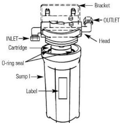
You can find them on the sump bracket.
Staple sales slip or cancelled check here.
Proof of the original purchase date is needed to obtain service under the warranty.
IF YOU NEED SERVICE
Inside you will find many helpful hints on how to use and maintain your water system properly. You'll find many answers to common problems in the Before You Call For Service section. If you review our chart of Troubleshooting Tips first, you may not need to call for service at all.
If you do need service, you can relax knowing help is only a phone call away. A list of toll-free customer service numbers is included in the back section.
IMPORTANT SAFETY INFORMATION. READ ALL INSTRUCTIONS BEFORE USING.
⚠ WARNING! For your safety, the information in this manual must be followed to minimize the risk of property damage or personal injury.
SAFETY PRECAUTIONS
- Check with your local public works department for plumbing codes. You must follow these guidelines as you install the Water Filtration system.
■ Use the Water Filtration system on a potable, safe-to-drink, home COLD water supply only. The filter cartridges will not purify the water, or make it safe to drink.
■ Do not use on a hot water supply (100°F. max.).
A WARNING: Do not use with water that is microbiologically unsafe or of unknown quality without adequate disinfection before or after the system. Systems certified for cyst reduction may be used on disinfected water that may contain filterable cysts.
PROPER INSTALLATION
This Water Filtration system must be properly installed and located in accordance with the Installation Instructions before it is used.
■ Install or store where it will not be exposed to temperatures below freezing or exposed to any type of weather. Water freezing in the system will damage it. Do not attempt to treat water over 100^ F.
WARNING: Discard all unused and packaging material after installation. Small parts remaining after installation could be a choke hazard.
- Your Water Filtration system will withstand up to 125 pounds per square inch (psi) water pressure. If your house water supply pressure is higher than 100 psi, install a pressure reducing valve before installing the Water Filtration system.
Read and follow this Safety Information carefully.
SAVE THESE INSTRUCTIONS
Using the Water Filtration System and About the Filter Cartridge
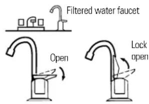
The countertop faucet dispenses filtered drinking water when opened. It has a hand-operated, spring-loaded closed lever to prevent waste. You can keep the faucet open by pushing upward on the lever to lock it against the faucet spout.
Filter Cartridge Life—Several variables determine how long the cartridges will last in your Water Filtration system. These include:
1 How much water you use.
2 How much sediment, taste and/or odor, lead, or other unwanted substance, is in the water.
No matter which Water Filtration system you have, you should replace the cartridges every six months. In extremely poor water supplies, you may notice the return of the unwanted substance in your water before the six months are up. In this case the cartridges should be replaced immediately. If the system is also for lead or chemical contaminant removal, it is MORE IMPORTANT to replace the cartridges at least every six months.
NOTE: If the water supply contains high amounts of sediments, the carbon filters may plug prematurely, reducing filtered water flow to the system faucet. Cartridge replacement is needed to restore flow.
natural_image
Line drawing of a handstand with faucet handle (no text or symbols)Specification guidelines.
Many bad tastes and/or odors are removed from water using activated carbon filter cartridges. They are most often used to remove a chlorine taste and odor. They can also reduce other undesirable elements from drinking water supplies, such as organic chemical contaminants and lead.
NOTE: Small amounts of hydrogen sulfide (noticeable as “rotten egg” odor) may be reduced by taste and odor filters for a short time, but the carbon media is quickly exhausted. Other water conditioning equipment is usually required for the continuous treatment of hydrogen sulfide.
The Water Filtration system uses the following filter cartridges:
I. FXUTC—Taste & Odor Cartridge (3000-Gallon Capacity)
White with magenta end caps
- Reduces dirt, rust and sediment
- Reduces unpleasant tastes and odors
- Reduces chlorine
• 1-micron nominal particulate reduction
II. FXULC—Lead/Cyst Cartridge (1250-Gallon Capacity)
White with yellow end caps
- Reduces dirt, rust and sediment
- Reduces unpleasant tastes and odors
- Reduces Chlorine
- Reduces Lead
- Reduces Asbestos
- Reduces filterable cysts (such as cryptosporidium and giardia)
- Reduces Lindane (a pesticide)
• 0.5 micron nominal particulate reduction
Minimum - Maximum Supply Water Pressure—40–125 pounds per square inch (psi)
Minimum - Maximum Supply Water Temperature—40–100°F.
Inlet - Outlet—3/8" NPT
Rated Service Flow: 1.0 gpm (GN1S04C & GX1S04C)
0.6 gpm (GX1S15C)
Depending on the treatment needed for a specific water supply, the water filtration system can be customized using any combination of the preceding filter cartridge sets.
Important Installation Recommendations
Read entire manual. Failure to follow all guides and rules could cause personal injury or property damage.
- Check with your local public works department for plumbing codes. You must follow their guides as you install the Water Filtration system.
■ Use the Water Filtration system on a potable, safe-to-drink, home COLD water supply only. The filter cartridges will not purify water or make unsafe water safe to drink. DO NOT use on HOT water (100° F. max.).
■ Protect the Water Filtration system and piping from freezing. Water freezing in the system will damage it. - Your Water Filtration system will withstand up to 125 psi water pressure. If your house water supply pressure is higher than 100 psi during the day (it may reach higher levels at night), install a pressure reducing valve before the system.
WARNING: Do not use with water that is microbiologically unsafe or of unknown quality without adequate disinfection before or after the system. GX1S15C is certified for cyst reduction and may be used on disinfected water that may contain filterable cysts. The water should be tested periodically to verify that the system is performing satisfactorily. Small parts remaining after the installation could be a choke hazard. Discard safely.
Tools and Materials Required for Installation
■ Slotted and Phillips screwdrivers
■ Pliers and adjustable jaw wrench
■ Hand or battery powered drill and 1/4" bit (saddle valve installation)
■ Electric drill and drill bit to drill 3/4" hole (type as required) if mounting hole is needed for faucet
Be sure to use the proper procedure for drilling porcelain or stainless steel. Special drill bits may be needed.

CAUTION: To avoid damaging the sink, consult a qualified plumber or installer for drilling procedures. Special drill bits may be needed for porcelain or stainless steel.
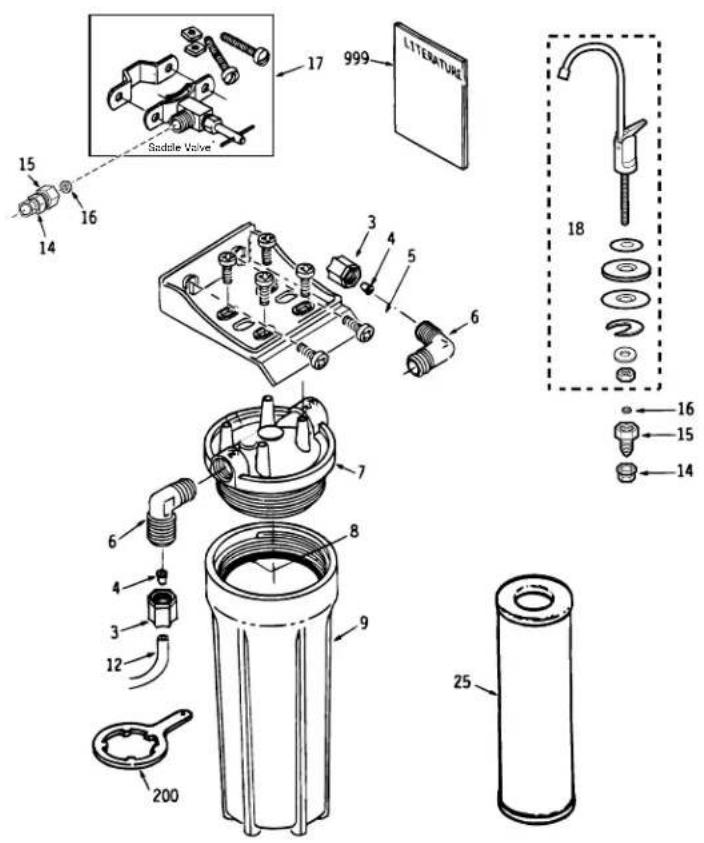
Contents included with the product:
■ Water filter assembly, including mounting bracket and screws
■ Product Literature (Owner's Manual and Installation, Product Data Sheet, Owner Product Registration Card)
■ Water supply/saddle valve
■ Filtered water faucet, for sink or countertop mounting
■ 3 /8" tubing and fittings to make all needed connections
■ Sump wrench
Installation Overview
flowchart
graph TD
    A["Sink"] --> B["Hot Cold"]
    B --> C["Water supply valve"]
    C --> D["Water out"]
    D --> E["Mounting screw (2)"]
    F["Model GX1S04C only"] --> G["Insert"]
    G --> H["Nut"]
    H --> I["Tubing"]
    I --> J["Washer"]
    J --> K["Adapter"]
    K --> L["Nut"]
    L --> M["Tubing"]
    M --> N["Water supply valve"]
    N --> O["Filtered water faucet"]
    O --> P["Water out"]
    style A fill:#f9f,stroke:#333
    style B fill:#f9f,stroke:#333
    style C fill:#ccf,stroke:#333
    style D fill:#ccf,stroke:#333
    style E fill:#ccf,stroke:#333
    style F fill:#cfc,stroke:#333
    style G fill:#fcc,stroke:#333
    style H fill:#fcc,stroke:#333
    style I fill:#fcc,stroke:#333
    style J fill:#fcc,stroke:#333
    style K fill:#fcc,stroke:#333
    style L fill:#fcc,stroke:#333
    style M fill:#fcc,stroke:#333
    style N fill:#fcc,stroke:#333
    style O fill:#cff,stroke:#333
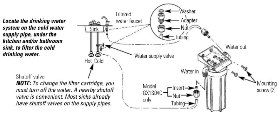
Feed Water Supply
Check and comply with local plumbing codes as you plan,
then install a cold feed water supply fitting. For new home installation using standard plumbing fittings, see first two illustrations below. A typical installation for existing homes using the saddle valve is shown in third illustration below.
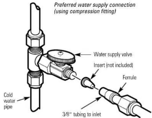
A. PREFERRED INSTALLATION
Turn off the cold water supply.
2 Complying with plumbing codes, install a fitting on the cold water pipe to adapt 3/8" OD tubing. A typical connection is shown in illustrations at right (parts not included). Make sure a water supply valve is used.

B. OPTIONAL HOME INSTALLATION Where codes permit
*For 1/2" OD or larger metal tubing only.
NOTE: Codes in the state of Massachusetts require installation by a licensed plumber and do not permit the use of the saddle valve. For installation, use plumbing code 248-CMR of the Commonwealth of Massachusetts.
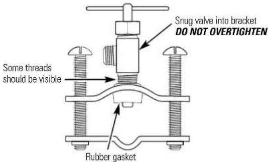
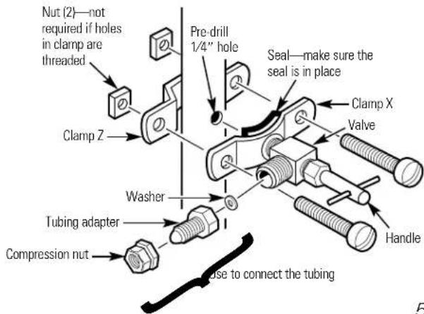
1 Turn off the cold water supply and attach saddle valve as shown in illustration at right.
A DANGER: To protect yourself from serious injury or fatal shock, use a battery-powered hand drill only to make the hole. DO NOT USE AN ELECTRIC DRILL.
2 Close the water supply valve by turning the handle clockwise.
3 Open the main water supply valve and several house faucets to purge air from the system. Close faucets when water runs smoothly.
Optional water supply connection (using saddle valve)*
*For 1/2" OD or larger metal tubing only.
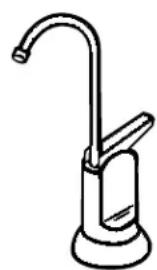
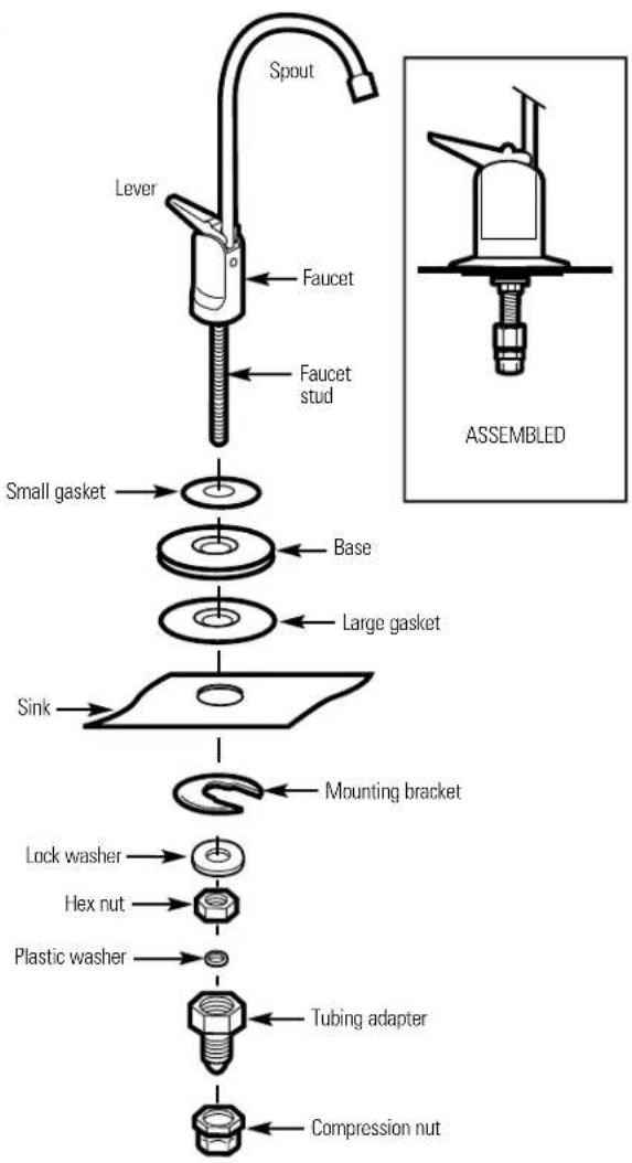
Faucet Installation
Be sure there is room underneath the sink to make the needed connections. Select one of the following places to install the faucet:
- IN an existing sink spray attachment or soap dispenser hole.
—IN a hole to be drilled in the sink top.
-IN a hole to be drilled in the countertop, next to the sink.
NOTE: Looking at second illustration at right, be sure the faucet base will fit flat against the surface at the selected location so the gasket will seal.
If drilling is needed, make a 3/4" dia. hole. Be sure to use the proper procedure for drilling porcelain or stainless steel. Special drill bits may be needed.
2 Place small gasket, base and large gasket (in that order) onto the faucet stem. Next, place lock washer and hex nut onto faucet stud.
3 Insert washer into tubing adapter. Securely tighten to faucet stud.
4 Feed the length of 3/8" OD tube from the bottom, up through the mounting hole. Connect to the tubing adapter as shown in second illustration, tightening the compression nut securely.
5 Remove the short shipping tube and insert the spout into the faucet body. Rotate spout into place.
6 Lower the faucet assembly into place on the underside of the mounting hole. Place the mounting bracket above the lock washer. While holding the mounting bracket in place, securely tighten the hex nut.
Mounting Bracket to Cabinet Wall
The bracket can be used as a template for marking the location of the mounting screws. When determining the location of the bracket make sure you leave 1-1/2" to 2" of free area under the sumps to allow for sump removal and enough space on either side to make the tubing connections.
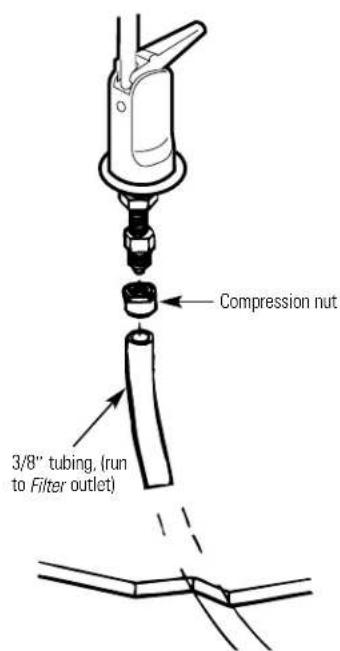
Tubing Connections—Compression Style (Models GX1S04C and GN1S04C)
7 Run the length of 3/8" tubing, connected to the bottom of faucet, to the filter system outlet. Allow enough slack in the tubing so the unit can be easily removed for filter changes. Measure and cut the end of the tubing square.
2 Slide a compression nut onto the end of the tubing and push a tubing insert into the tubing.
3 Connect the tubing and tighten the compression nuts securely.
4 Repeat the preceding steps to connect a length of tubing between the filter system inlet and the water supply/saddle valve (illustration in the Installation Overview section).

Tubing Connections—Push-In Style (Model GX1S15C)
7 Run the length of the 38" tubing, connected to the bottom of the faucet, to the filter system outlet (illustration above). Allow enough slack in the tubing so that the unit can be easily removed.
2 Measure and cut the end of the tubing square using a sharp cutter or knife. Remove any burrs (illustration A).
3 Inspect the end of the tubing, about 1 inch, to be sure there are no imperfections. It may be necessary to cut the tubing again.
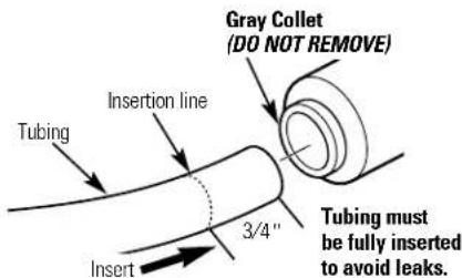
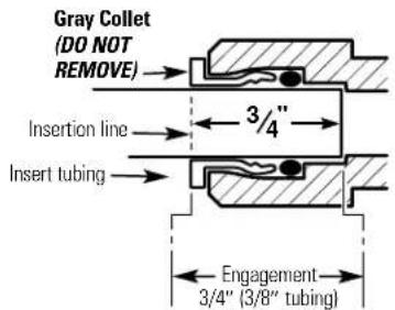
4 Mark the tubing for length of insertion. For 3/8" OD tubing the insertion length should be approximately 3/4 of an inch. Tubing must be fully inserted to avoid leaks.
DO NOT REMOVE GRAY COLLET. Push the tubing all the way into the fitting until it bottoms out. The insertion line should be hidden or barely visible (illustration B and C). Slightly pull on the tubing to verify engagement.
6 Repeat the procedure to connect the tubing between the filter system inlet and the water supply/saddle valve (illustration in the Installation Overview section).
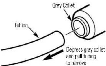
7 To remove tubing (illustration D), depress and hold gray collet. Pull tubing to remove.
NOTE: Avoid installing the unit where the tubing is pulled at a sharp angle. This type of installation may cause the fittings to leak. If using tubing other than what is supplied, be sure it is high quality, exact size and roundness, and has a smooth surface.
A

B
©
D
Filter Cartridge Installation or Replacement
CAUTION: Never remove the sumps when water pressure is in the Water Filtration system.
7 Close the water supply/saddle valve to the filter. (See illustration in the Installation Overview section for location of the water supply valve.) Open the filtered water faucet.
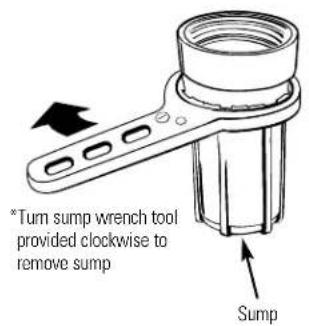
2 Remove the sump, using the sump wrench tool*, from the filter head by rotating the sump as shown. Be careful, the sump may be full of water. Be sure to keep the large o-ring seal.
3 If you are replacing a filter cartridge, remove and discard the used filter cartridge.
4 Be sure the inside of the sump is clean. Thoroughly wash the inside of the sump with hot, soapy water and rinse.
5 Remove the wrapper from the new filter cartridge and insert the filter cartridge in the sump. Some cartridges fit either way, while others fit only one way. Observe markings on the cartridge.
NOTE: The Water Filtration system uses two different types of filter cartridges. Be sure to install them correctly. See Specification Guidelines for a complete list of filter performance characteristics.
6 Lightly lubricate the o-ring seal in the sump with clean food grade silicone grease (silicone grease is available through GE Parts and Services: 1-800-626-2002 Part number: WS60X10005). Be sure it is fully seated in its groove.
7 Hold the sump up to the filter head, aligning the center hole in the cartridge with the protrusion on the bottom of the head. Failure to obtain proper alignment may cause damage to the filter and/or filtration system, which will degrade filter performance.
8 Being careful not to cross-thread, rotate the sump onto the filter head and tighten securely by hand.
NOTE: If the sump will not tighten up to the head or if you feel resistance, you may have the cartridge in upside down or misaligned. Take the cartridge out and check for correct orientation or alignment and reassemble.
9 Turn on the filtered water faucet. Then, slowly open the water supply valve and allow the filter housing to fill.
10 Close the filtered water faucet. Then, check for leaks between the sump and the head.
NOTE: If leaking, turn off the water supply and turn on the filtered water faucet. Disassemble the filter housing and check the o-ring for cuts, flat spots, etc., and sealing surfaces for foreign material. Clean the o-ring and lightly lubricate with clean silicone grease. Carefully press into the groove in the sump. Reassemble and check for leaks.
The filter cartridges contain activated carbon. When new, turn on the filtered water faucet for five minutes to flush the system.
12 Place filter change label on sump, inside cabinet door, or in another convenient location. Write in date of filter change for future reference. Filters should be changed every six months.
Flush Procedure
Whenever water of unknown quality is passed through the GE Water Filtration system, filter elements should be discarded and the filtration system flushed.
Circumstances that may require flushing the system are:
■ Boil-water advisory.
■ Flooding of the GE Water Filtration system.
■ Long-term non-use.
The procedure for flushing the GE Water Filtration system is:
1 See Filter Cartridge Replacement section and follow steps 1, 2, 3, and 4.
2 Next, reinstall the sumps (without the filter elements), turn water on, and flush water through the faucet for one minute.
3 Then, turn water off, remove sumps, empty water out of sumps and install new filter elements.
4 Follow steps 5-10 in the Filter Cartridge Replacement section to complete.
Before you call for service...

Troubleshooting Tips Save time and money! Review the chart below first and you may not need to call for service.
| Problem Possible Causes What To Do | ||
| Water contains tiny black particles | New filter cartridges contain activated carbon, which is a carbon particles to purge from the cartridge. Turn off the harmless black powder. faucet when the water is clear. | |
| Water has air bubbles and is cloudy | Air in system after installation. | Will go away after water runs for a while. |
| Chlorine taste and/or odor in the product water | The filter cartridge is no longer removing chlorine from the water supply. | Replace filter cartridge. |
| Water dispenses very slowly | Filter may have an integral flow restrictor. filter. If flow rate is unacceptable replace the filter with one that does not have an integral flow restrictor. | |
| The filter has been installed for too long. Replace filter cartridge. | A six-month change-out period is recommended. | |
| The filter cartridge has become clogged. Replace filter cartridge. | High sediment levels can cause premature clogging. | |
| Push-in fittings are leaking (GX1S15C) | Tubing may not be installed properly. the tubing is installed to the proper depth. | Fully follow the installation instructions (page 7) and be sure |
| Tubing may be damaged. | Examine the end of tubing (approx. 1 inch) for defects such as scratches, grooves, roundness, etc. Trim tubing and fully reinstall. | |
*NOTE: Codes in the state of Massachusetts require installation by a licensed plumber and do not permit the use of the saddle valve. For installation, use plumbing code 248-CMR of the Commonwealth of Massachusetts.
General Electric parts catalog.
| G | G | G | ||||
| X | X | N | ||||
| 1 | 1 | 1 | ||||
| S | S | S | ||||
| 1 | 0 | 0 | ||||
| 5 | 4 | 4 | ||||
| C | C | C | ||||
| REF. NO. PART NO. PART DESCRIPTION | ||||||
| 0001 WS02X10001 SCREW #10-14 X 3/4" 4 4 8 | ||||||
| 0002 WS28X10010 MOUNTING BRACKET 1 1 1 | ||||||
| 0003 | WS22X10008 | NUT 3/8" TUBE | 2 | - | - | |
| 0004 | WS22X10007 | INSERT 3/8" TUBE | - | 2 | - | |
| 0005 WS02X10003 SCREW #10-14 X 1-1/4" 2 2 2 | ||||||
| 0006 WS22X10002 ELBOW 3/8" NPT X 3/8" (compression) 2-- | ||||||
| 0006 | WS22X10032 | ELBOW 3/8" NPT X 3/8" (push-in) | - | 2 | 2 | |
| 0007 WS19X10011 HEAD | 1 1 1 | |||||
| 0008 | WS03X10001 | O-RING 3-3/8" X 3-5/8" | 1 | 1 | 1 | |
| 0009 WS30X10002 SUMP | 1 1 1 | |||||
| 0012 WS07X10008 TUBING 3/8" X 20 FT-WH | 1 1 1 | |||||
| 0014 WS02X10004 NUT 3/8" | 2 2 2 | |||||
| 0015 WS03X10003 ADAPTER TUBING | 2 2 2 | |||||
| 0016 WS03X10002 WASHER | 2 2 2 | |||||
| 0017 WS15X10008 SADDLE VALVE /SUPPLY | 1 1 1 | |||||
| 0018 WS15X10022 FAUCET ASM. (nonmonitored) | 1 1- | |||||
| 0025 FXUTC | FILTER SET-TASTE & ODOR | 1-- | ||||
| FXULC | FILTER SET-LEAD/CYST | - | 1- | |||
| 0200 WX5X140 | WRENCH SUMP | 11- | ||||
| 0999 49-50040 | PM MANUAL USE & CARE/INSTALLATION | |||||
| 1 1 1 | ||||||
Service Telephone Numbers.
GE Answer Center ^® 800.626.2000
The GE Answer Center ^® is open 24 hours a day, 7 days a week.

In-Home Repair Service 800-GE-CARES (800-432-2737)
Expert GE repair service is only a phone call away.

Special Needs Service 800.626.2000
800-TDD-GEAC (800-833-4322)
GE offers, free of charge, a brochure to assist in planning a barrier-free kitchen for persons with limited mobility.

Service Contracts 800-626-2224
Purchase a GE service contract while your warranty is still in effect and you'll receive a substantial discount. GE Consumer Service will still be there after your warranty expires.
Parts and Accessories 800-626-2002
Individuals qualified to service their own appliances can have parts or accessories sent directly to their homes (VISA, MasterCard and Discover cards are accepted).
Instructions contained in this manual cover procedures to be performed by any user. Other servicing generally should be referred to qualified service personnel. Caution must be exercised, since improper servicing may cause unsafe operation.

Service Satisfaction
If you are not satisfied with the service you receive from GE:
First, contact the people who serviced your appliance.
Next, if you are still not pleased, write all the details—including your phone number—to:
Manager, Consumer Relations, GE Appliances, Appliance Park, Louisville, KY 40225
GE Water Filtration System Warranty.

All warranty service provided by our SmartWater™ Authorized Servicer Network.
For service, call 800-GE-CARES.
For The Period Of: GE Will Replace:
One Year Any part
From the date of the original purchase
of the Water Filtration system (excluding filters) which fails due to a defect in materials or workmanship. During this limited one-year warranty, GE will also provide, free of charge, all labor (does not include service trip to home) to replace the defective part.
What GE Will Not Cover:
■ Service trips to your home to teach you how to use the product.
■ Improper installation.
■ Failure of the product if it is abused, misused, or used for other than the intended purpose or used commercially.
■ Use of this product where water is microbiologically unsafe or of unknown quality, without adequate disinfection before or after the system. Systems certified for cyst reduction may be used on disinfected water that may contain filterable cysts.
■ Filter cartridges.
■ Replacement of house fuses or resetting of circuit breakers.
■ Damage to the product caused by accident, fire, floods or acts of God.
■ Incidental or consequential damage to personal property caused by possible defects with this appliance.
This warranty is extended to the original purchaser and any succeeding owner for products purchased for home use within the USA. In Alaska, the warranty excludes the cost of shipping or service calls to your home.
Some states do not allow the exclusion or limitation of incidental or consequential damages. This warranty gives you specific legal rights, and you may also have other rights which vary from state to state. To know what your legal rights are, consult your local or state consumer affairs office or your state's Attorney General.
Cartouches de filtration—installation
| G | G | G |
| X | X | N |
| 1 | 1 | 1 |
| S | S | S |
| 1 | 0 | 0 |
| 5 | 4 | 4 |
| C | C | C |
natural_image
Line drawing of a handbar with faucet handle (no text or symbols)Entrada-Salida—3/8" NPT

- Water Filtration System
- Owner's Manual and Installation
- Safety Information ....2
- Operating Instructions .....3
- Installation Instructions ...4-9
- Troubleshooting Tips
- Customer Service
- NSF®
- IMPORTANT!
- IF YOU NEED SERVICE
- IMPORTANT SAFETY INFORMATION. READ ALL INSTRUCTIONS BEFORE USING.
- SAFETY PRECAUTIONS
- PROPER INSTALLATION
- SAVE THESE INSTRUCTIONS
- Using the Water Filtration System and About the Filter Cartridge
- Specification guidelines.
- The Water Filtration system uses the following filter cartridges:
- Important Installation Recommendations
- Tools and Materials Required for Installation
- Installation Overview
- Feed Water Supply
- PREFERRED INSTALLATION
- OPTIONAL HOME INSTALLATION Where codes permit
- Faucet Installation
- Mounting Bracket to Cabinet Wall
- Tubing Connections—Compression Style (Models GX1S04C and GN1S04C)
- Tubing Connections—Push-In Style (Model GX1S15C)
- Filter Cartridge Installation or Replacement
- Flush Procedure
- Circumstances that may require flushing the system are:
- The procedure for flushing the GE Water Filtration system is:
- Before you call for service...
- General Electric parts catalog.
- Service Telephone Numbers.
- GE Water Filtration System Warranty.
- For The Period Of: GE Will Replace:
- What GE Will Not Cover:
Brand : GE
Model : GX1S01C
Category : Water filter