CEHPT90B - Basket CONTINENTAL EDISON - Free user manual and instructions
Find the device manual for free CEHPT90B CONTINENTAL EDISON in PDF.
| Brand | Continental Edison |
| Model | CEHPT90B |
| Product type | Extractor and recirculation hood |
| Dimensions (W x D x H) | 900 x 600 x 735 mm (estimated from minimum installation space) |
| Exhaust pipe diameter | 150 mm |
| Power supply | 220-240 V, 50 Hz |
| Maximum motor power | 79.4 W (at maximum efficiency point) |
| Number of speeds | 10 (9 levels + booster function) |
| Maximum airflow | 713.8 m³/h (booster mode) |
| Maximum air pressure | 435 Pa |
| Noise level | 52 dB (low speed) to 72 dB (booster mode) |
| Lighting | Linear LED 4W (type DBL-4-S-650) |
| Energy efficiency class | A++ |
| Annual energy consumption | 20.3 kWh/year |
| Main functions | Timer 3 min, automatic booster stop after 5 min, touch control |
| Maintenance and cleaning | Clean grease filter every month; replace charcoal filter once a year |
| Minimum safety distance | 800 mm for gas hobs, 700 mm for electric hobs |
| Available spare parts | Charcoal filter, grease filter, LED bulb (DBL-4-S-650) |
| Mode of use | Extraction (outside venting) or recirculation (charcoal filter) |
| General information | Professional installation recommended; do not use steam cleaner |
Frequently Asked Questions - CEHPT90B CONTINENTAL EDISON
User questions about CEHPT90B CONTINENTAL EDISON
0 question about this device. Answer the ones you know or ask your own.
Ask a new question about this device
Download the instructions for your Basket in PDF format for free! Find your manual CEHPT90B - CONTINENTAL EDISON and take your electronic device back in hand. On this page are published all the documents necessary for the use of your device. CEHPT90B by CONTINENTAL EDISON.
USER MANUAL CEHPT90B CONTINENTAL EDISON
natural_image
Abstract geometric shapes resembling partial crescent and angular segments (no text or symbols)Continental Edison
natural_image
Exterior view of a modern office building (no signage)CEHPT60B & CEHPT90B
Hotte Plan De Travail En Verre - Downdraft Range Hood
Installation (Mode extraction)....13
natural_image
Close-up of a metallic LED strip with green LED indicators and mounting bracket (no text or symbols visible)natural_image
Close-up of a metallic LED strip with small yellow indicator lights and a circular base (no text or symbols visible)Installation (Mode extraction)
natural_image
Diagram of a mechanical device emitting air through a fan or fan assembly (no text or symbols)natural_image
Technical line drawing of a mechanical device with no visible text or symbolsnatural_image
Two grayscale illustrations: a rectangular object with a handle and a hand holding a tray, both enclosed in a dashed border (no text or symbols)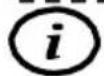
text_image
600 mm 95mmtext_image
855 mm 95mmnatural_image
Technical line drawing of a mechanical device with a downward arrow indicating force or motion (no text or symbols present)natural_image
Technical line drawing of a mechanical or architectural component with no visible text or symbolsnatural_image
Technical line drawing of a mechanical assembly with mounting brackets and internal components (no text or symbols)natural_image
Diagram of a mechanical or electrical component with directional arrows and circular features, no readable text or symbols present.Note: Make sure that you have suficient cable reserver for the plug connection!
natural_image
Technical line drawing of a mechanical assembly with a frame and housing (no text or symbols)natural_image
Technical line drawing of a mechanical assembly with a housing, housing unit, and pipe connection (no text or symbols)natural_image
Diagram of a pipe system inside a brick wall and adjacent to an electrical cabinet (no text or labels)natural_image
Technical line drawing of a mechanical or electrical assembly with a brick wall and connected piping (no text or symbols)text_image
Simple hand-drawn circles with a checkmark in the bottom-right corner, likely for selection or confirmation.
text_image
c | * | □ | ▼ | e
text_image
Simple diagram with four circles and a checkmark, likely indicating selection or confirmation.Read this guide carefully before installing and using this product and keep it for future reference.
Thank you for choosing Oceanic. This Use and Maintenance Guide is designed to provide you with all the necessary information regarding the installation, use and maintenance of the appliance.
In order to operate the unit properly and securely, read this user guidecarefully before installing and using the product.
Contents
Find some informations....32
Important safety instructions....33
Lamp....39
Description of the pieces....41
Installing the hood....42
Preparation before installation....43
Installation (Mode extraction)....43
Installation data / dimensions....44
Important information befo-re installing the appliance....45
Using the extractor hood as an exhaust air hood (with air extracted to outdoors)....46
Converting the extractor hood to a circulation hood....46
Mounting the carbon filter....46
Electrical connection....47
Mounting the hood....48
Informations on air flow....53
Cleaning....55
Cleaning....56
Control Panel Functions....57
Technical informations....58
Further information....60
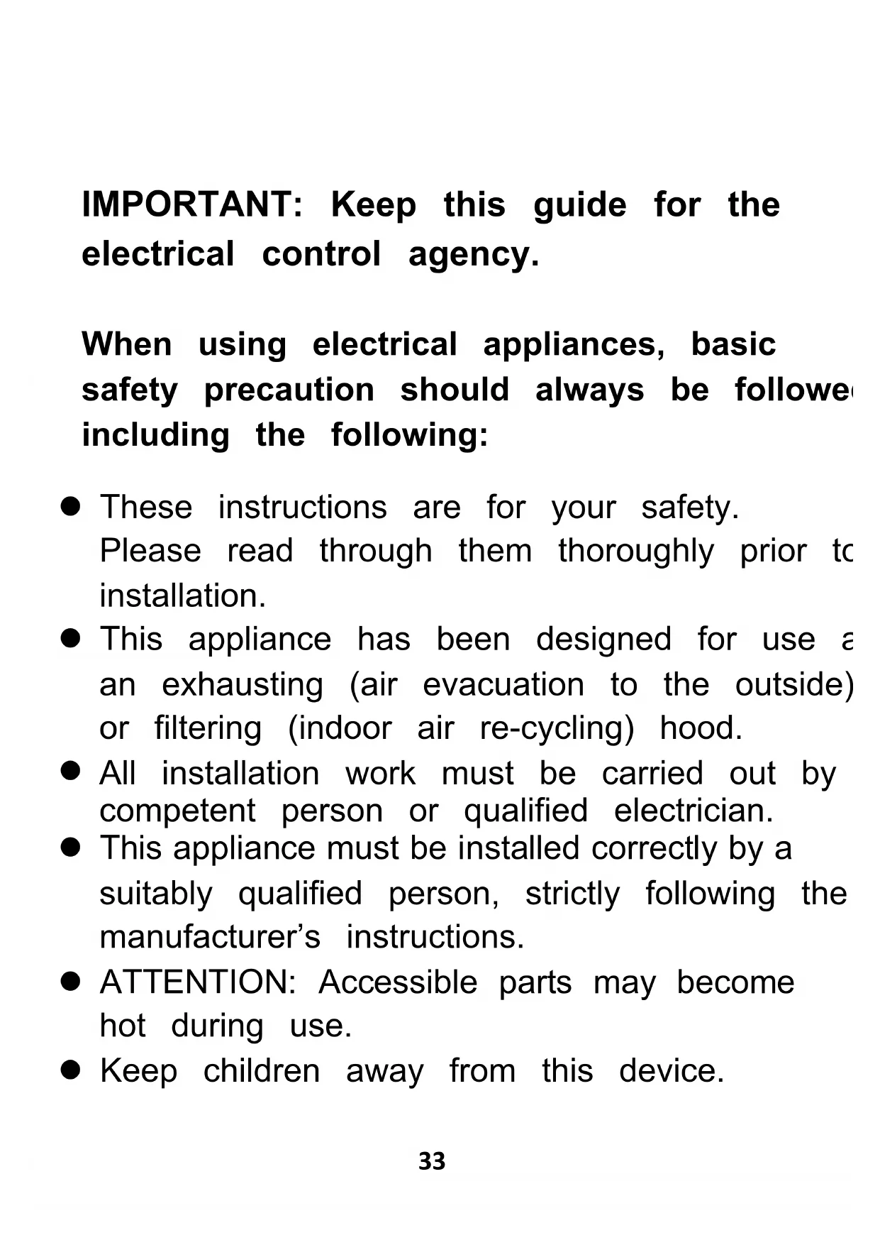
IMPORTANT: Keep this guide for the electrical control agency.
When using electrical appliances, basic safety precaution should always be followed including the following:
- These instructions are for your safety.
Please read through them thoroughly prior to installation. - This appliance has been designed for use a an exhausting (air evacuation to the outside) or filtering (indoor air re-cycling) hood.
- All installation work must be carried out by competent person or qualified electrician.
- This appliance must be installed correctly by a suitably qualified person, strictly following the manufacturer's instructions.
- ATTENTION: Accessible parts may become hot during use.
- Keep children away from this device.
- The Manufacturer highly recommends that this appliance be kept out of the reach of babies and small children.
- This appliance can be used by children age from 8 years and above and persons with reduced physical, sensory or mental capabilities or lack of experience and knowledge if they have been given supervision or instruction concerning use of the appliance in a safe way and understand the hazards involved. Children shall not play with the appliance. Cleaning and user maintenance shall not be made by children without supervision.
- Regularly check the power plug and power cord for signs of damage. If the supply cord is damaged, it must be replaced by themanufacturer, its service agent or similarly qualified persons in order to avoid a hazard.
- Do not allow the electric cables to touch the hot parts of the appliance.
- Make sure that the power cord is not caug under or in the appliance and avoid damage the power cable.
- Do not use flammable sprays in close vicinity to the appliance.
- Please dispose of the packing material carefully.
- We also recommend that you pay special attention during use and during cleaning. Refer to the instructions in the "CLEANING" section.
● A steam cleaner is not to be used. - The appliance is not intended to be operated by means of external timeror separated remote-control system.
- Warning: When using for extraction, refer to the national regulations for building ventilation systems. Do not connect the exhaust pipe to VMC type ventilation system, to a flue (chimney, boiler, ...). Also check the absence of disturbance with the ventilation of the roof when there are gas appliances (water heater gas stove, ...). If in doubt, use the hood in recycling mode.
- Proper ventilation of the room must be provided when the hood is used simultaneously with appliances using gas or other fuel.
- Air must not be discharged into a flue that is used for exhaustingfumes from appliances burning gas or other fuels. The rules concerning the evacuation of the air must be respected.
- Warning: The hood may stop working during electrostatic discharge (e.g.lightning). This involves no risk of damage. Switch off the electricity supply to the hood and reconnect after one minute.
- To avoid the risk of fire, clean the metal fi regularly and closely watch and regulate pan containing hot oil.
- Do not flame under the range hood.
- Do not use the hood if it shows signs of or imperfection. Contact customer services.
- When installing the appliance, make sure that the following distances between the top of cooker or hob and the lowest part of the hood must be observed:
Gas hobs: 800mm
Electric hobs: 700mm
- Warning: There is a risk of electric shock an fire if cleaning is not carried out in accordance with the instructions.
- Warning: For safety reason, please use only the same size of fixing or mounting screw which are recommended in this instruction manual.
● Warning: Failure to install the screws or fixi device in accordance with these instructions may result in electrical hazards. - Warning: Before connecting the hood: switch off the electricity supply and check that the supplied voltage and frequency coincide with that indicated on the appliance nameplate.
Electrical Shock Hazard
Failure to follow these instructions can result in death, fire, or electric shock.
For model CEHPT60B: The available lamps and the correspondenceILCOS D codes and lamp pictures: Use type lamp(or use in alternative type lamp)DBL-3-S-350(ILCOS D code in according to standard IEC 61231).
-LED modules-linear lamp
-Max wattage:3W
-Voltage range:≤25V
-Dimensions:diameter length 350mm
-Pictures:
natural_image
Close-up of a metallic LED strip with green and yellow indicator lights, mounted on a metal bracket (no text or symbols visible)Note: If the supply LED bulb is damaged, it may be replaced by the manufacturer, its service agent or similarly qualified persons in order to avoid a hazard.
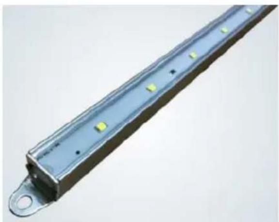
For model CEHPT90B:The available lamps and the correspondenceILCOS D codes and lamp pictures:Use type lamp(or use in alternative type lamp)DBL-4-S-650(ILCOS D code in according to standard IEC 61231).
- LED modules-linear lamp
- Max wattage:4W
-Voltage range:≤25V
-Dimensions:diameter length 650mm
-Pictures:

natural_image
Close-up of a metallic LED strip with green LED indicators and mounting flange (no text or symbols visible)Note: If the supply LED bulb is damaged, it may be replaced by the manufacturer, its service agent or similarly qualified persons in order to avoid a hazard.
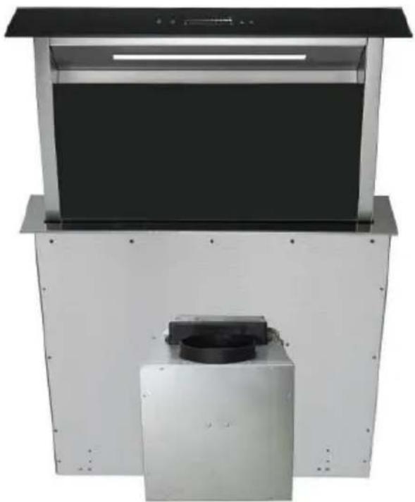
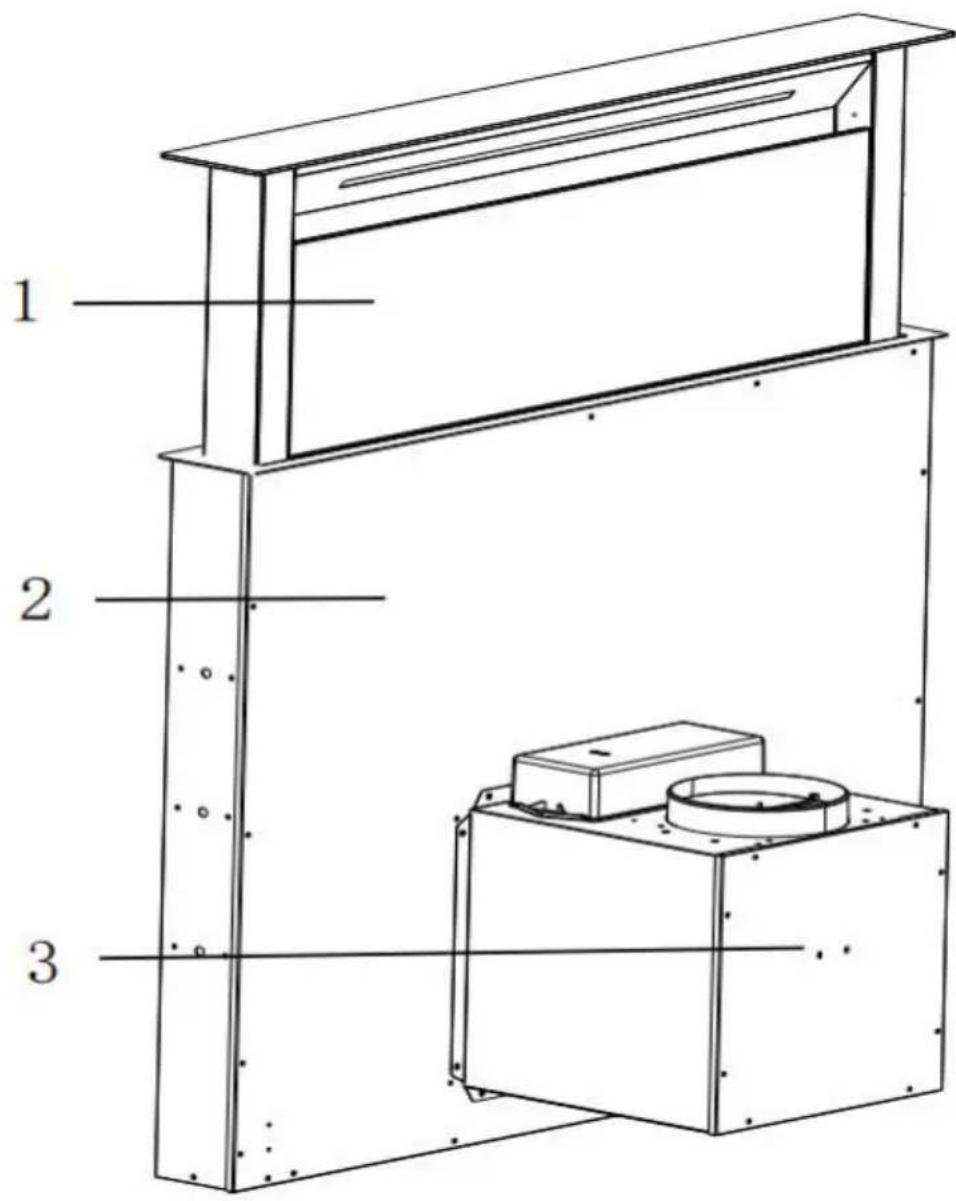
- Glass panel
2 Hood body.
3.Motor assembly
text_image
1 2 3| Index | Description | Quantity | |
| PL-1 | Hood body |  | 1 |
| PL-2 | Motor assembly | 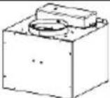 | 1 |
| PL-3 | Glass panel | 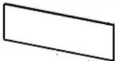 | 1 |
| PL-4 | Screw(M4 x 8 mm) | 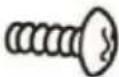 | 10 |
| PL-5 | Screw(ST4 x 30 mm) | 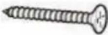 | 2 |
| PL-6 | Screw(M5 x 12 mm) | 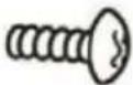 | 8 |
| PL-7 | Case leg | 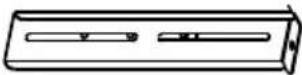 | 2 |
| PL-8 | 8 × 6 (Not include) | 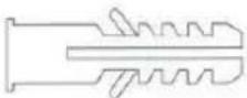 | 2 |
| PL-9 | Carbon filter | 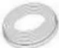 | 6 |
| PL-10 | Aluminum pipe( 150- 153mm ; 2meter flexible tube) |  | 1 |
Preparation before installation

ATTENTION
Carefully remove the carton. Wear gloves to protect your hands from sharp edges.

ATTENTION
Remove the protective film from the product before putting it into service.
Installation (Mode extraction)
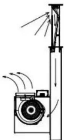
If the wall has an opening to the outside, your hood may be connected as shown in the diagram
below using the suitable
exhaust pipe (not supplied), such as ductwork, flexible aluminum or other non-flammable material with an inside diameter of less than 150mm.
natural_image
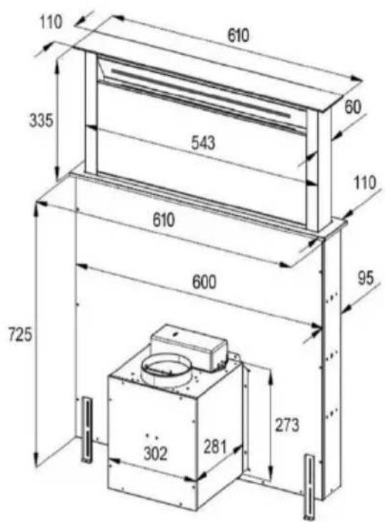
Diagram of a mechanical device emitting air flow, showing fan blades and internal components (no text or labels)1 Installation data / dimensions
Note:
Before installation, check that the dimensions indicated correspond to the dimensions of the product.
During and after installation of the ap- pliance, use a sp level to ensure that the cooker hood is level.
Otherwise, grease and/or condensation may accumulate in the corners of the appliance.
text_image
110 610 335 543 60 110 610 600 95 725 302 281 273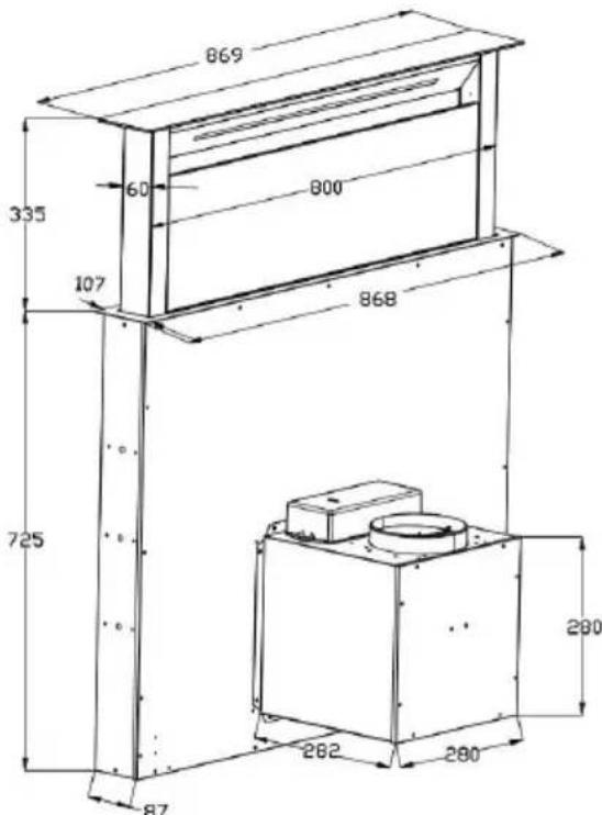
text_image
869 335 60 800 107 868 725 280 282 280 872. Important information befo-re installing the appliance:
- Clean the environment thoroughly before and after installation so that no dust or construction debris can be sucked in during initial operation.
- Check the condition and load-bearing capacity of the electrical cables.
The installation of the appliance by a specialist is recommended.
Follow the description of the work steps in the mounting chapter and all further instructions.
In the execution with air exhausted out-doors, the vapours are extracted via an air exhaust hose fixed to the connector ring.
- The diameter of the exhaust air hose must conform to that of the connector ring.
- The exhaust air hose must not be led through a shaft together with gas pipes, hot air pipes etc.
- Route the exhaust hose as straight as possible away from the hood. The maximum permissible bend to the outside is 120°.
-
If a smoke non-return valve is used or is planned, check whether it can open and close freely after the installation of the exhaust air hose.
-
Using the extractor hood as an exhaust air hood (with air extracted to outdoors)
If the extractor hood has been fitted at the factory with a carbon filter, this must be removed for exhaust air operation. It is only practicable to use this when operating your hood in circulation mode.
- Converting the extractor hood to a circulation hood
If you wish to use the hood as a circulati-on hood, you must mount the activated carbon filter(s) to the fan motor before using the hood. If not included in the scope of supply, you must obtain the carbon filter(s) from the supplier of your extractor hood.
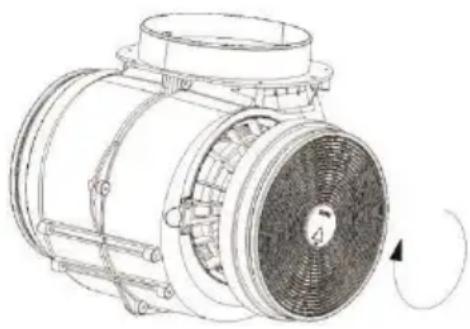
- Mounting the carbon filter
Place the carbon filter into the unit and turn it clockwise. Repeat the same on the other side.
NOTE:
natural_image
Technical line drawing of a mechanical fan or motor assembly with no visible text or symbolsClose
Make sure the filter is securely locked. Otherwise, it can fall and cause danger.
When charcoal filters are used, the suction power is decreased.
The carbon filter must be replaced at least once a year depending on how frequent the cooker hood used.
6.Electricalconnection
Only connect the appliance to the po-wer supply once it is properly installed.
Never install the appliance if the data on the rating plate (V) does not agree with your supply voltage. You will find the rating plate inside the appliance, behind the grease filter.
If the extractor hood is fitted with a standard connector plug, connect this to an easily accessible standard socket.
If the appliance is not fitted with a con- nector plug, a two-pole switch, confor-ming to standards with a minimum open contact gap of 3 mm is to be installed by an authorized tradesman in an easily ac-cessible location.
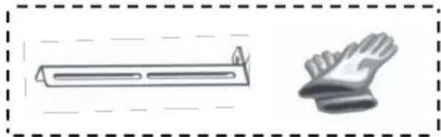
7. Mounting the hood

Note: The ventilation system has sharp edges. Use s gloves.
natural_image
Illustration of a towel rack and a pair of gloves (no text or symbols)
The mounting time is 1-3 hours and there are 2 people required for assembly.
- For CEHPT90B, make sure your installation space is not less than 900mm(L)x600(W)x735(H); For CEHPT60B, make sure your installation space is not less than 600mm(L)x600(W)x735(H).
- Before mounting, all appropriate core holes for the installation of the ex-haust hose must be present or made.
- Select the installation position so that the appliance can be easily connected to the power supply.
- Please get an exhaust hose 150 mm
with two hose clamps (not included!)
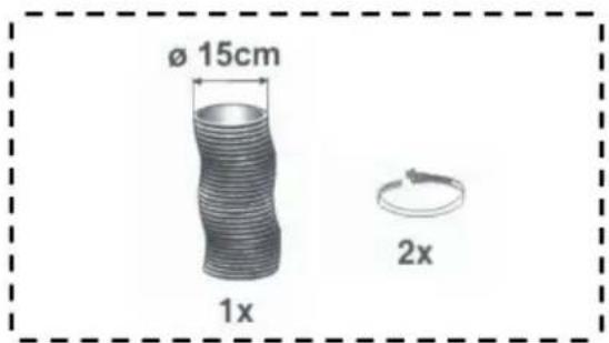
text_image
ø 15cm 1x 2x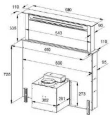
text_image
110 610 60 335 543 110 610 800 95 725 302 281 273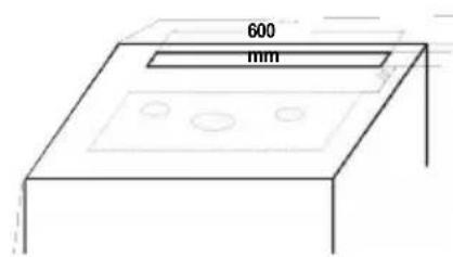
text_image
600 mm- Model CEHPT60B : Provide the worktop with the mat-ching cutout (600 x 95 mm) for the ventilation system.
text_image
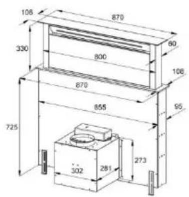
108 870 90 330 800 106 870 855 95 725 302 281 273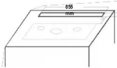
text_image
855 mm- Model CEHPT90B : Provide the worktop with the mat-ching cutout (855 x 95 mm) for the ventilation system.
Note: Before carving, check that the dimensions indicated correspond to the dimensions of the product.
natural_image
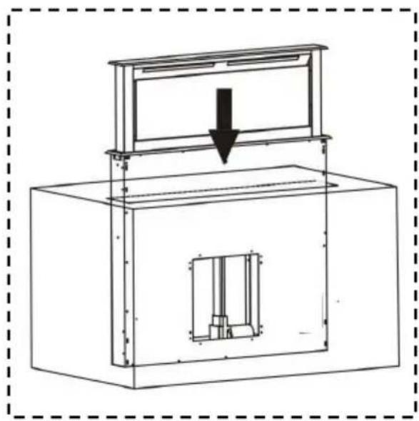
Technical line drawing of a mechanical device with a downward arrow indicating force or movement (no text or symbols present)- Insert the ventilation system into the cut-out and conn them by means of the holding rails under the counte andonthebody.
• The glass plate is used for visual impression and is human frontofthegreasefilters.
Thefunctionof youretractorhood is not affectedbythis.
natural_image
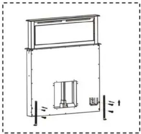
Technical line drawing of a mechanical or architectural component with no visible text or symbols- Mount the case legs.
natural_image
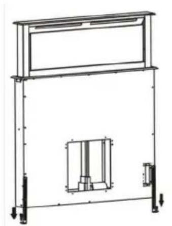
Technical line drawing of a mechanical assembly with mounting brackets and internal components (no text or symbols)- Adjust the appropriate height of the case legs to give the appliance additional stability.
natural_image
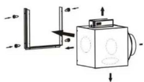
Diagram of a mechanical assembly with directional arrows and components (no text or symbols)- You have the option to connect the motor unit depending on the location of the opening provided for this purpose on the ventilation housing. Turn the ventilation outlet in the appropriate direction and screw the motor to the bracket.
Note: Make sure that you have suficient cable reserver for the plug connection!
natural_image
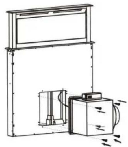
Technical line drawing of a mechanical assembly with a frame and housing (no text or symbols)- Join the plug contacts together and check the function of the appliance.
- Screw the motor unit with the bracket to the housing.
natural_image
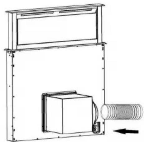
Technical line drawing of a mechanical assembly with a housing, housing block, and cylindrical component (no text or symbols)Attach the exhaust duct to the ven-tilation outlet of the motor unit and connect it to the provide exhaustairopeningbymeansofthehoseclamps.
Note: Images are for illustration purpo-ses only and may vary
1
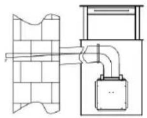
natural_image
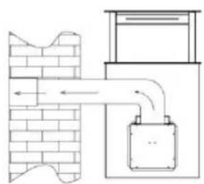
Diagram of a brick wall with a pipe and a gas cylinder, no text or symbols present2
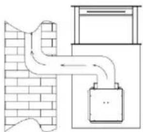
natural_image
Diagram of a pipe system inside a brick wall and adjacent to a cabinet (no text or symbols)Fig. 1: Exhaust air into the open air
Fig. 2: Exhaust air via air shaft/fireplace
- The exhaust air line should be as short and straight a possible.
- To avoid excessive noise or a reduced extraction capacity the diameter of the exhaust air pipeline should not be less than 150 mm.
- Use or form only large radius bends. Small radius bends reduce the extrac-tion capacity of the hood.
- Use only smooth pipelines or flexible hoses of non-flammable materials for the exhaust air pipeline
- If the exhaust air pipeline is horizontally routed, there must be a minimum gradient of 1 cm per metre or an incli-nation angle of 2^ . (Fig. 3) Otherwise condensation water could run into the extractor hood motor.
- If the exhaust air is directed into an exhaust air duct, the end of the entry fitting must directed in the direction of flow.
3
natural_image
Technical line drawing of a mechanical or electrical assembly with no visible text or symbolsFig. 3: inclination angle of the exhaust air pipeline
- If the exhaust air is directed into an exhaust air duct, the end of the entry fitting must be directed in the direction of flow.
- If the exhaust air pipeline is routed though cool rooms, lofts etc. there can be a large temperature drop within the individual parts of the pipeline, resulting in sweating or condensation water production. This renders outlet pipeline insulation necessary.
- In some cases a condensation water barrier must be installed in addition to adequate insulation
The manufacturer is not responsible for any faults occurring through non-com-pliance with the above information and provisions.
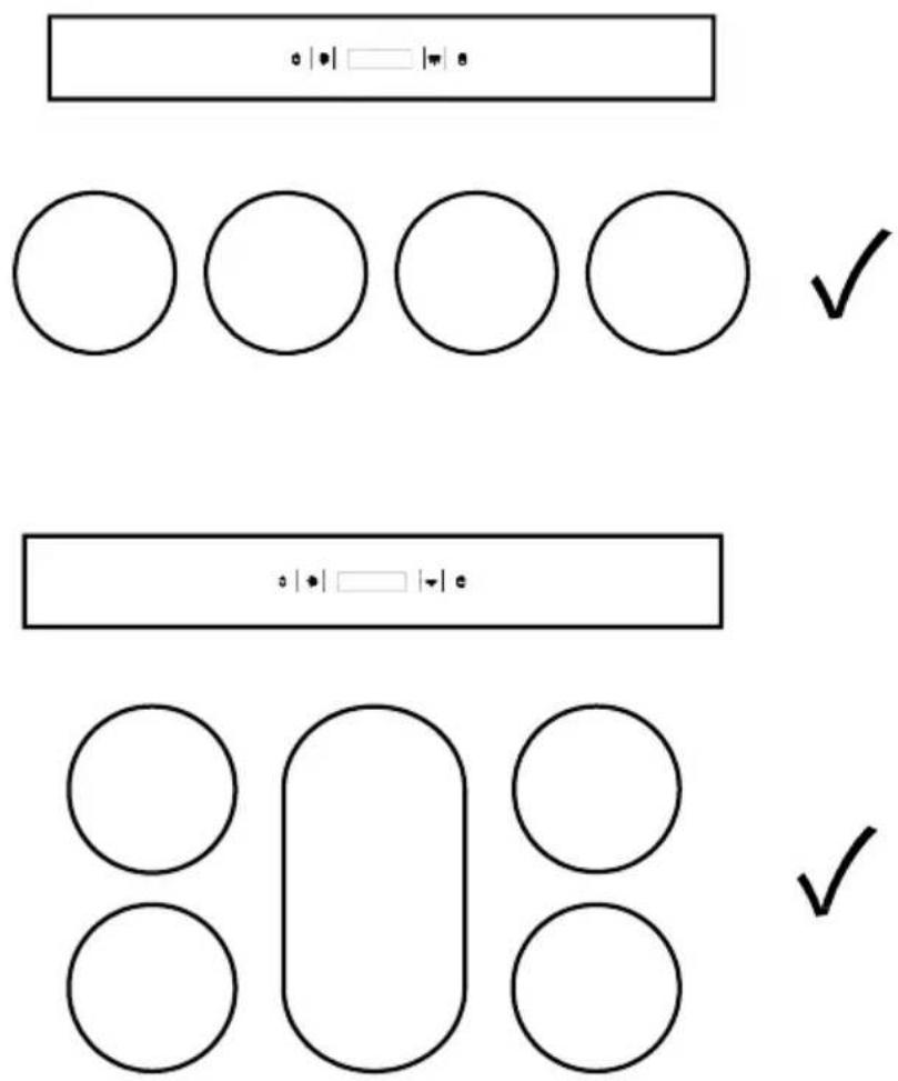
- The hob should have a maximum width of 92 cm.
- The cooking zones should be arranged side by side and not one behind the other, as shown in the following illustration (top view):
Regarding the instructions for the cleaning and maintenance of the appliance, please refer to below paragraphs of this manual.
Attention! Before cleaning switch the unit off and pull out the plug.
Regular Cleaning
Use a soft cloth moistened with hand-warm mildly soapy water or household cleaning detergent. Never use metal pads, chemical, abrasive material or stiff brush to clean the unit.
Monthly Cleaning for Grease Filter
ESSENTIAL: Clean the filter every month can prevent any risk of fire.
The filter collects grease, smoke and dust. It is directly affecting the efficiency of the cooker hood. If not cleaned, the grease residue (potential flammable) will saturate on the filter. Clean it with household cleaning detergent.
Operating the hood
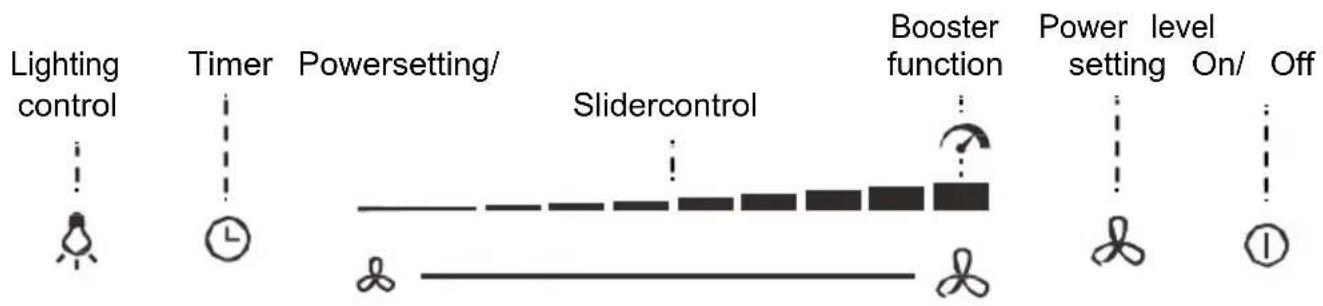
flowchart
graph LR
    A["Lighting control"] --> B["Timer"]
    B --> C["Powersetting/Slidercontrol"]
    C --> D["Booster function"]
    D --> E["Power level setting On/Off"]
    style A fill:#f9f,stroke:#333
    style B fill:#ccf,stroke:#333
    style C fill:#cfc,stroke:#333
    style D fill:#fcc,stroke:#333
    style E fill:#ffc,stroke:#333
On/Off
- If you keep the on/off key pressed for 3 seconds, the hood is extende By pressing the key again, the hood retracts.
Important! : Make sure that the ho is not blocked or obstructed when racting or extending. There is a risk a pot being lifted (e.g. by a protru handle) and hot contents being spilt
- Briefly pressing the key in operating mode stops operation (appliance beeps, lighting remains unaffected).

Power level setting
• The appliance has a total of 10 pc levels (9 + booster function).
- Selecta power level from 1 to 9 by using the slider control or tap the desired level directly.
- You can also use the key to set the desired power level: Pressing briefly will increase the power in single stoholding it leads to a smooth, faster setting.
After level 9, the setting returns to level 1.
- Toimmediately adjust the power to the lowest level, press the key b theslider.
Booster function
- The 10th speed level is the booster / high performance level.
- To start the booster and maximize power, touch and hold the key below the slider for 2 seconds (A beep sounds, highest level indicator flashes).
• To stop the booster function, use the slider to set a lower power level.
• After 5 minutes the booster function is automatically deactivated.
Timer (automatic switch-off):
- Pressing the keyduringoperation causesthehoodtoswitchoffautomaticallyafter3minutes(witha beep). The flashing of the inicator light indicatestherunningcountdown.
- To deactivate the timer, press the key again.
Lighting control:
- To switch the light on and off, press the ⚙ keyinworkingstate.
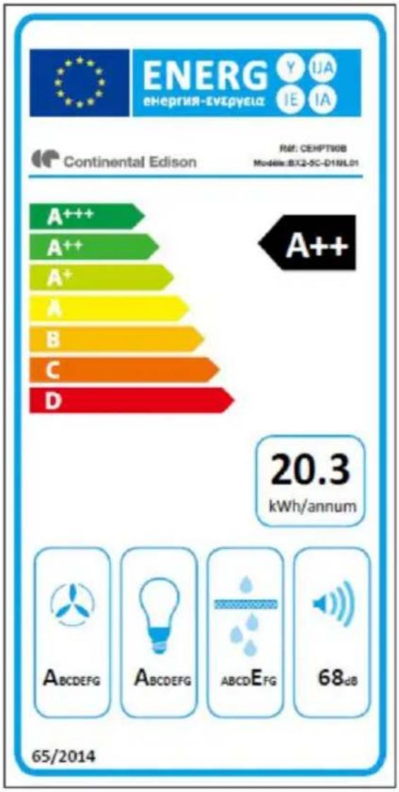
| Symbol | Value | Unit | |
| Model identification | Ref.:CEHPT60B & CEHPT90B | ||
| Models:BX2-5C-D1J6L01 &BX2-5C-D1I9L01 | |||
| Annual Energy Consumption | AEC_hotte | 20.3 | kWh/a |
| Energy Efficiency class | A++ | ||
| Time increase factor | f | 0.6 | |
| Fluid Dynamic Efficiency | FDE_hotte | 40.0 | |
| Fluid Dynamic Efficiency class | A | ||
| Energy Efficiency Index | EEI_hotte | 37.7 | |
| Measured air flow rate at best efficiency point | Q_BEP | 262.9 | m^3/h |
| Measured air pressure at best efficiency point | P_BEP | 435 | Pa |
| Maximum air flow(Boost setting) | Q_max | 713.8 | m^3/h |
| Maximum air flow(highest setting) | 640.0 | m^3/h | |
| Air flow at working point(highest setting) | 604.1 | m^3/h | |
| Air flow at working point(lowest setting) | 322.7 | m^3/h | |
| Measured electric power input at best efficiency point | W_BEP | 79.4 | W |
| Nominal power of the lighting system | W_L | 4 | W |
| Average illumination of the lighting system on the cooking surface | E_moyen | 3W:654W:189 | lux |
| Lighting Efficiency | LE^hotte | 3W:21.74W:47.3 | lux/W |
| Lighting efficiency class | A | ||
| Grease Filtering Efficiency | GFE^hotte | 63.9 | |
| Grease Filtering Efficiency class | E | ||
| Measured power consumption off mode | P_O | 0.43 | W |
| Sound power level | L_WA | Boost setting:72Highest setting:68Lowest setting:52 | dB |
The method of measurement and calculation of the above table is in accordance with Commission Regulation (EU) No 65/2014 and 66/2014
bar
| Category | Value (kWh/annum) | |---|---| | A+++ | 20.3 | | A++ | 20.3 | | A+ | 20.3 | | A | 20.3 | | B | 20.3 | | C | 20.3 | | D | 20.3 | 65/2014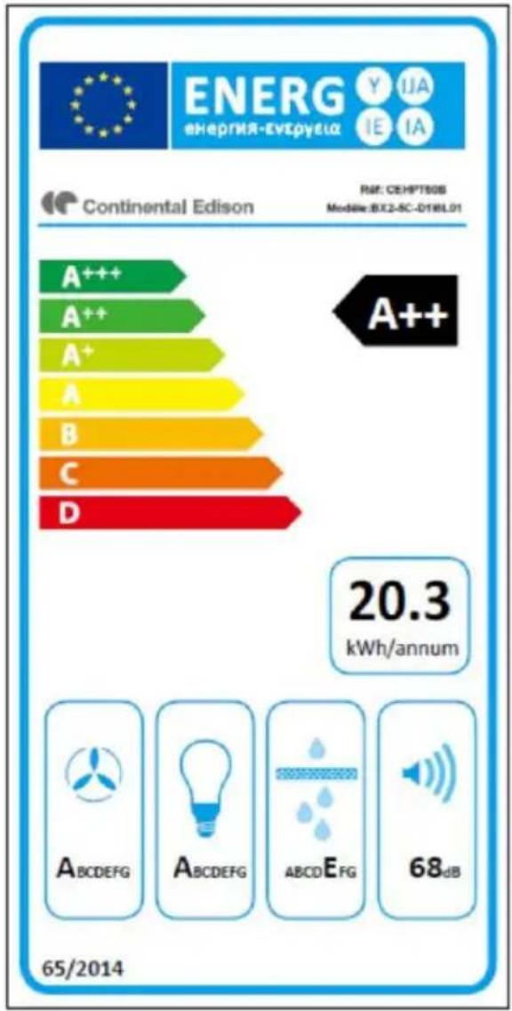
bar
| Level | Energy Consumption (kWh/annum) | |---|---| | A+++ | 20.3 | | A++ | 20.3 | | A+ | 20.3 | | A | 20.3 | | B | 20.3 | | C | 20.3 | | D | 20.3 | 65/2014CONTINENTALEDISON
120-126 quai de Bacalan
CS11584
33000 Bordeaux
Importé par A.M.C.
The following recommendations specify how to reduce the overall environmental impact of the cooking process.
(1) Install the range hood in a suitable location with good ventilation.
(2) Clean the cooker hood regularly so that nothing blocks the air.
(3) Do not forget to turn off the hood lamp once cooking is complete.
(4) Do not forget to turn off the range hood once cooking is complete.
Disassembly Information
Do not disassemble the unit in a manner that is not indicated in the op instructions. This device must not be disassembled by the user. At the e life cycle, the appliance must not be disposed of with household waste. I recycling tips, please contact your local administration or dealer.
ENVIRONMENTAL PROTECTION
Electrical and electronic equipment is subject to selective collection. Do not dispose of used electrical and electronic equipment with unsorted househow waste; instead, take part in their selective collection.
It is for this reason that your appliance, as indicated by the symbol on its nameplate or on the packaging, must never be thrown in a public or bin intended for household waste.
The user has the right to deposit the device in public collection places it selectively dispose of the waste to be recycled or reused for other applications. The packaging is recyclable..
natural_image
Pure electrical circuit lines without any symbols