
Nettun@ 7000open - Cash register OLIVETTI - Free user manual and instructions
Find the device manual for free Nettun@ 7000open OLIVETTI in PDF.
| Product Type | Cash register |
| Brand | Olivetti |
| Model | Nettun@ 7000open |
| Dimensions (H x W x D) | 180 x 360 x 360 mm |
| Weight | 3.5 kg |
| Power Supply | 100-240 V, 1.5 A, 50-60 Hz (input); 24 V DC, 1.875 A (output) |
| Average Power Consumption | 12 W |
| Main Display | 10.1" LCD touch screen (resolution 1024 x 600) |
| Customer Display | Backlit LCD display 2 lines x 20 characters |
| Built-in Printer | Thermal, speed up to 260 mm/s, paper width 80/60/57.5 mm |
| Interfaces | 4 USB 2.0 ports, 2 COM ports, 1 Ethernet port, 1 VGA port, 1 HDMI port, 1 cash drawer port |
| Processor | Intel Dual Core Atom D2550 |
| RAM Memory | Up to 4 GB DDR3 |
| Storage | 32 GB SSD |
| Main Functions | Fiscal sales recording, multi-currency management, POS software options |
| Safety | Do not expose to water or heat, unplug before cleaning, do not open during printing |
| Maintenance | Clean with a damp cloth, do not use corrosive products |
| Certifications | CE marking, class A (possible radio interference) |
| Package Contents | Cash register, external power supply, quick guide, thermal paper roll, drawer fixing kit, paper reducer 57.5/60 mm |
Frequently Asked Questions - Nettun@ 7000open OLIVETTI
User questions about Nettun@ 7000open OLIVETTI
0 question about this device. Answer the ones you know or ask your own.
Ask a new question about this device
Download the instructions for your Cash register in PDF format for free! Find your manual Nettun@ 7000open - OLIVETTI and take your electronic device back in hand. On this page are published all the documents necessary for the use of your device. Nettun@ 7000open by OLIVETTI.
USER MANUAL Nettun@ 7000open OLIVETTI
Publication issued by:
Olivetti S.p.A.
Telecom Italia Group
Via Jervis, 77 - 10015 Ivrea (TO)
Copyright © 2015, by Olivetti
All rights reserved
This manual describes the cash register sold with the name NETTUN@7000open.
For more detailed information on how to use the cash register functions, the User Manual can be downloaded from the Olivetti site (www.olivetti.com) that contains detailed information.
The manufacturer reserves the right to carry out modifications to the product described in this manual at any time without any notice.
The quality requirements of this product are attested through display of CE marking on the product.

Warning:
This is a Class A appliance.
In a residential environment, it may cause radio interference in which case the user may be required to take adequate measures.
Your attention is drawn to the following actions which could compromise the conformity attested to above and also product characteristics:
- incorrect power supply;
- incorrect installation, incorrect or improper use or use not in compliance with the warnings provided in the User's Manual furnished with the product;
- replacement of original components or accessories with others of a type not approved by the manufacturer, or performed by unauthorised personnel
User Safety
Connect the machine to a nearby and readily accessible current outlet.
Access the print unit area only to replace accessories. Do not use the machine above or close to sources of heat (e.g. radiators) or very close to water (e.g. swimming-pools or showers).
To effectively disconnect the appliance, remove the plug of the power cord from the current outlet. To clean the machine, disconnect it from the current outlet, use a damp cloth. Do NOT not use corrosive liquids.
TABLE OF CONTENTS
INTRODUCTION 1
INSTALLATION 2
PACKAGE CONTENTS 2
INSTALLATION PREREQUISITES 3
CONNECTING THE CASH REGISTER TO THE POWER SUPPLY. 4
POWERING ON THE CASH REGISTER 6
INSERTING PAPER 7
SAFETY PRECAUTIONS AND GENERAL RULES FOR USE 7
INSERTING THE PAPER ROLL 8
REGULATING THE NEAR-END-OF-PAPER SENSOR 10
PRINTING UNIT 10
GETTING TO KNOW YOUR CASH REGISTER 11
MAINCOMPONENTS 11
CUSTOMER DISPLAY 13
BUILT-IN THERMAL PRINTER 15
POWER UNIT. 15
ELECTRICAL SPECIFICATIONS 15
POWER SUPPLY DATA 15
ENVIRONMENTAL SPECIFICATIONS 15
SIZE AND WEIGHT 15
DIRECTIVE
1. FOR COUNTRIES IN THE EUROPEAN UNION (EU)
The disposal of electric and electronic devices as solid urban waste is strictly prohibited: it must be collected separately. The dumping of these devices at unequipped and unauthorized places may have hazardous effects on health and the environment. Offenders will be subjected to the penalties and measures laid down by the law.
TO DISPOSE OF OUR DEVICES CORRECTLY:
a) Contact the Local Authorities, who will give you the practical information you need and the instructions for handling the waste correctly, for example: location and times of the waste collection centres, etc.
b) When you purchase a new device of ours, give a used device similar to the one purchased to our dealer for disposal.
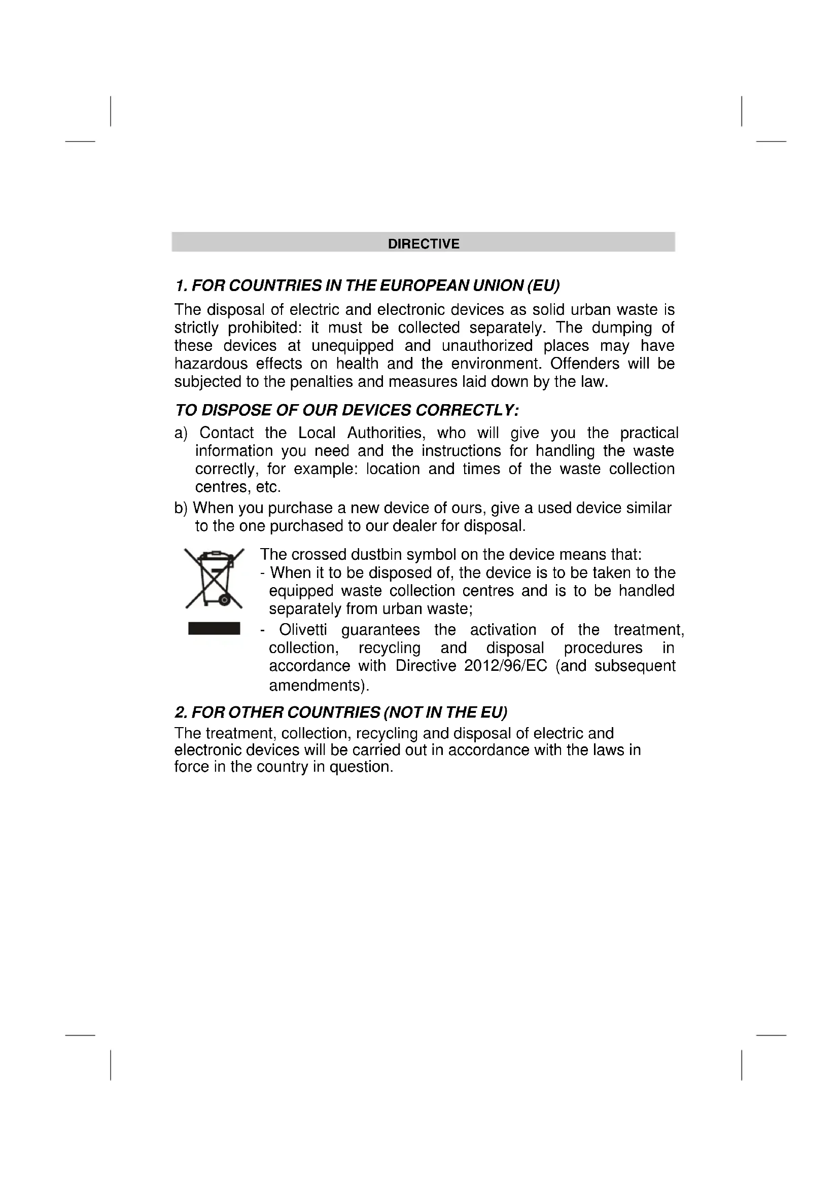
The crossed dustbin symbol on the device means that:
- When it to be disposed of, the device is to be taken to the equipped waste collection centres and is to be handled separately from urban waste;
- Olivetti guarantees the activation of the treatment, collection, recycling and disposal procedures in accordance with Directive 2012/96/EC (and subsequent amendments).
2. FOR OTHER COUNTRIES (NOT IN THE EU)
The treatment, collection, recycling and disposal of electric and electronic devices will be carried out in accordance with the laws in force in the country in question.
INTRODUCTION
The cash register described in this manual can be used for registering, for fiscal purposes, the data related to the sales of goods and services, and represents an indispensable tool for managing a sales point.
Key features of the product and its performance are a 10.1" touch screen monitor with adjustable tilt, a printing unit with an automatic cutter for issuing tickets of widths 80 mm, 57.5 or 60 mm.
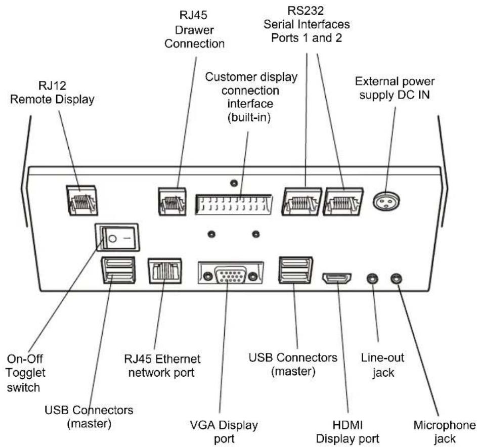
The machine has two serial interfaces, four USB interfaces and an Ethernet connection port for connecting over the network to external devices such as barcode readers and additional printers for issuing receipts and tickets.
INSTALLATION
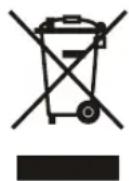
PACKAGE CONTENTS
The cash register is delivered in a single package containing the following components:
Cash register
- External power unit with power cord
- Quick Start guide with instructions for use
- Roll of thermo | paper in initial supply
- Printer fixing kit
- Adapter for handling paper rolls of widths 57.5 and 60~mm
INSTALLATION PREREQUISITES
The installation steps for the cash register are:
- connect the cash register to the mains electricity supply
- power on the cash register
- insert the paper
- connect the barcode reader (not indispensable for general use)
- connect the drawer (not indispensable for general use)
- connect other external peripherals (not indispensable for general use).
Warning For the cash register to be operational, the paper roll must be loaded.
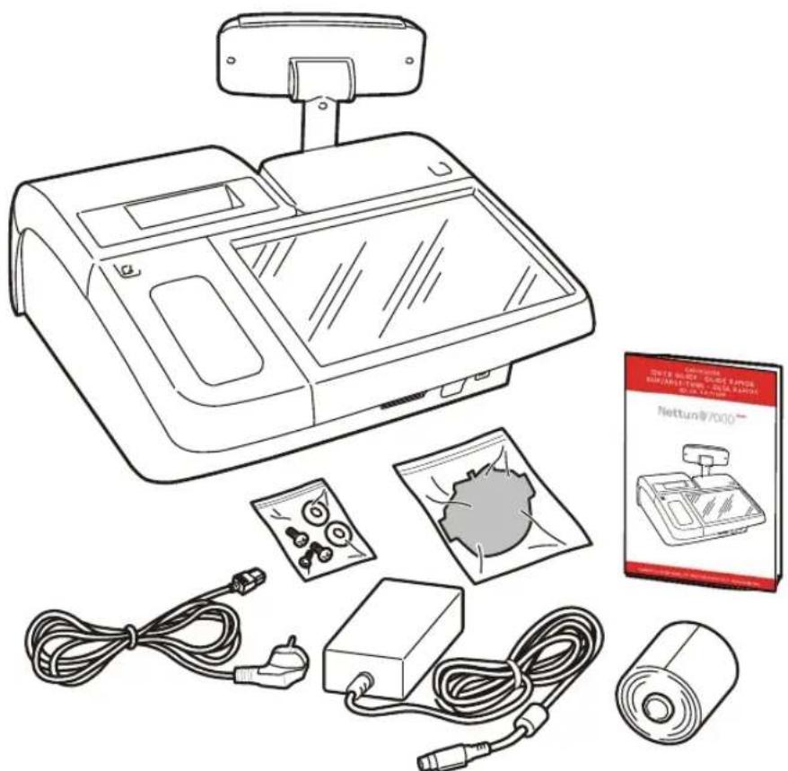
CONNECTING THE CASH REGISTER TO THE POWER SUPPLY
Connect the external power unit first to the cash register (A) and then to the 220V mains power supply (B).
GeneralWarnings:
- Do not insert foreign bodies into the cash register.
- If the cash register is to remain unused for a long period, disconnect it from the mains power socket.
- To disconnect the appliance from the electrical power supply, remove the plug from the mains power socket; remember to use a power socket near to the machine that can be reached easily.
- The appliance is certified as safe to use and compliant with applicable standards only if used with an external power unit meeting the following specifications:
Power Supply Unit (alternative)
Input: 100-240V, 50/60Hz-1.2A
Output: 24 V DC 3.75A
- The appliance is certified as safe to use and compliant with applicable standards only if used with an external power unit of type:
Power Unit specifications:
Power Supply Unit (alternative)
Input: 100-240V, 50/60Hz-1.2A
Output: 24 V DC 3.75A
POWERING ON THE CASH REGISTER
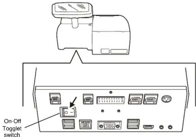
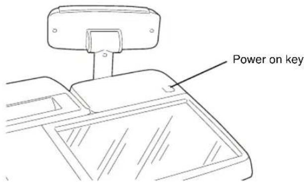
To power on the cash register, you must first have connected the power unit to the cash register as previously described, then positioning the Toggle switch On and then press the key. When the key is pressed the cash register powers on and, after a brief interval, displays the sales environment. The cash register is now operational.
When the cash register is on ( key lighted), it can be powered off by pressing the key for about 1 second. This starts the power off phase if no other operations are in progress.
Warning If the cash register is not used for a certain amount of time, it automatically enters energy saving mode. The touch screen is switched off but the key remains lighted.
To return the cash register at any time to operating mode and use it again just touch the touch screen.
INSERTING PAPER
Warning
Exclusively approved thermal paper should be used on the cash register. If other types of thermal paper are used, in particular paper that is too thin, the ticket may not be fed correctly. Also the writing and logos on the back of the paper must not be visible due to the transparency of the paper.
SAFETY PRECAUTIONS AND GENERAL RULES FOR USE
Note
before using the product, read this section carefully.
- Make sure that the electrical specifications of the power unit used with the cash register (230 V AC, 50/60 Hz) correspond with those of the mains power supply.
- Connect the cash register to a standard-compliant electrical installation.
- Do not expose the printer to direct sunlight, or install it near heat or water sources, or in environments that are very damp or dusty.
- Should smoke, odours or unusual noises be detected coming from the cash register, disconnect it from the mains power supply and contact the Technical Services desk.
- To avoid the risk of injury, do not touch any of the parts indicated in these figures:
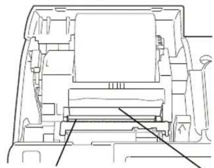

Printhead: very hot
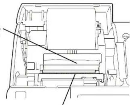
Cutter counterblade: very sharp:
Automatic cutter blade: very sharp
Manual cutter blade: very sharp
- Do not pull the paper out of the output slot with the cover of the cash register closed.
- Do not op en the cover of cash register while it is printing.
- Do not carry out any other interventions on the cash register apart from those described for problem resolution.
- Do not attempt to disassemble or modify the product.
Warning
The procedures described in the following can be used when you
are inserting a paper roll on the cash register for the first time, or when replacing a used paper roll. Paper rolls of widths 80mm , 60mm and 57.5mm can be used on the printer, however before using 57.5 and 60mm rolls, you must first install the paper roll Adapter Kit. When a paper roll must be replaced you are informed by a message that appears on the monitor.
| 1. Open the printer cover. | |
| 2. Press the release lever (A) on the control mechanism downwards (until you hear an opening click), then lift the upper part of the printer. | |
| 3. Orienting the paper roll as indicated in the figure here, unwind about 20 cm of the paper, then insert the roll into its bay making sure to keep hold of the unwound paper. | |
| 4. Still keeping hold of the unwound paper, close the printer by pressing simultaneously on both right and left sides of the paper output slot. Make sure that the unit closes fully on both sides (you should hear a click from the closing mechanism). | |
| 5. Pull through the paper and cut it using the manual cutter. | |
| 6. Close the top cover of the printer. |
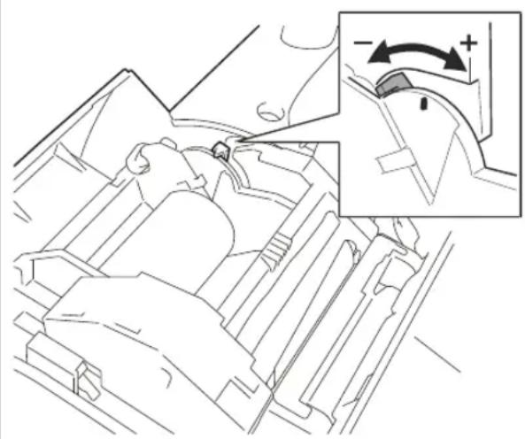
REGULATING THE NEAR-END-OF-PAPER SENSOR
Note
The near end-of-paper sensor is set up in the factory to function correctly for the most common types of paper roll.
If you notice that when the near end-of-paper condition is notified, there is either too little or too much paper left, you can adjust the sensor setting.
The setting of the sensor depends on the diameter of the paper roll hub. For a hub of a given diameter, moving the lever towards the rear of the machine will result in less paper being present on the hub when notification is given, while moving the lever towards the front will result in more paper being present. To regulate the near end-of-paper sensor, proceed as follows.
- Open the cover of the cash register by pressing fully down the release button.
- If a roll of paper is loaded, remove it.
- Move the green adjustment lever in the direction of the cash register operator panel to be notified earlier (for hubs of larger diameters). Move the lever towards the rear of the main module to be notified later (for hubs of smaller diameters).
- Load the paper roll.
PRINTING UNIT
The printing unit is composed of a single thermal printer. It comprises of a bay for holding a paper roll of 80mm width or, installing the adapter supplied, of 57.5 or 60 mm widths.
GETTING TO KNOW YOUR CASH REGISTER
MAIN COMPONENTS
The cash register and its principal components.
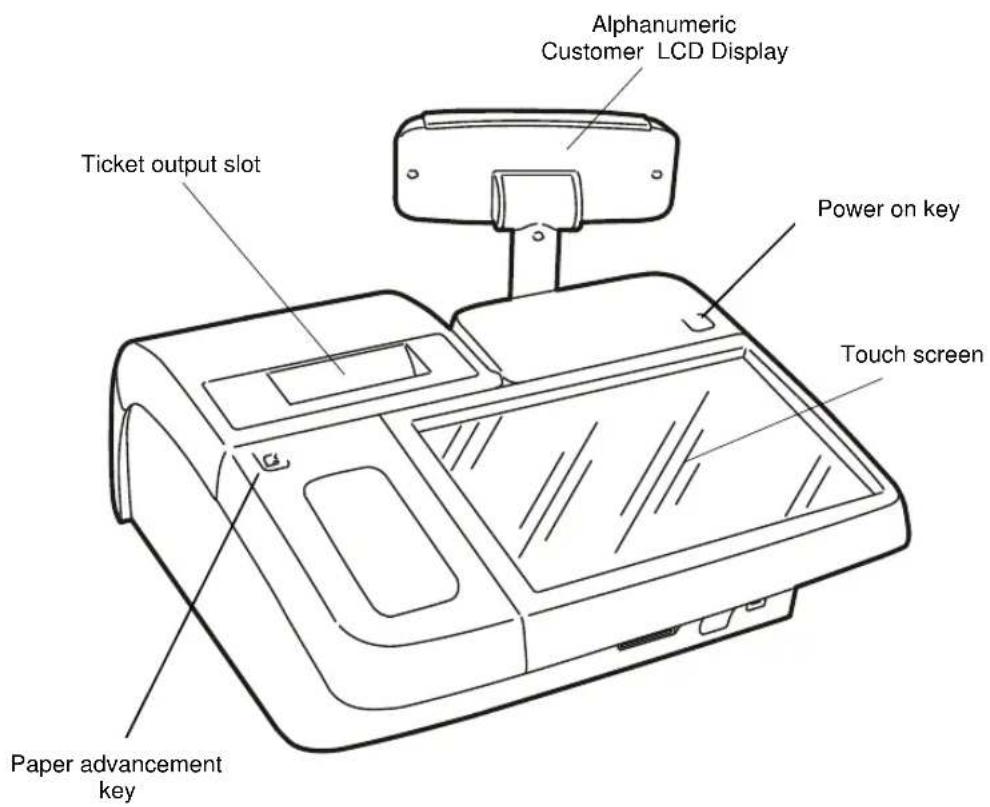
CUSTOMER DISPLAY
The customer display consists of a liquid crystal display with 2 rear-lit rows displaying up to 20 alphanumeric characters per row.
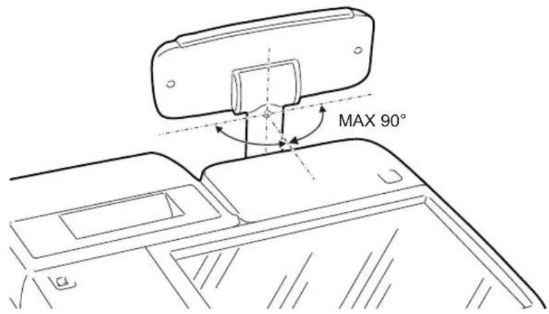
The display is mounted on a height-adjustable special support which can be swivelled to the most appropriate position as shown in the figure.
The touch screen is used to interact with the cash register and provides access to all the cash register functionalities.
Information and methods for using the screen depend on the operating system installed on your system (for more information refer to the Instructions supplied with the operating system).
TECHNICAL SPECIFICATIONS
CASING
Resin body and cover.
10.1" touch screen video
- Customer liquid crystal display.
CUSTOMER DISPLAY
The customer display consists of a rear-lit height-adjustable LCD display, rotatable and tiltable, comprised of 2 rows displaying up to 20 alphanumeric characters per row.
MODULE SPECIFICATIONS
PC BOARD Intel Dual Core ATOM CEDARVIEW processor D2550. Intel NMI10 Chip Set.
SYSTEM MEMORY DDR3 1066MHz 2 SODIMM up to 4GB.
- MASS STORAGE 1 x 2.5" 32GB SSD SATA interface.
- INTERFACES 4 x USB 2.0 ports
2xCOMports
1 x Ethernet port
1 VGA port
1 HDMI port
1 Line out audio
1 Microphone
1 Customer display
1 Second remote customer display
1 Cash drawer port
ADJUSTABLEVIDEO TFT 10.1 inch.
Resolution 1024 x 600
Interface LVDS 18bit, 3.3V
Backlit LED
- TOUCH SCREEN 4 wire resistive.
SOFTWARE AVAILABLE
- Windows Embedded POSready 7 (32 bit)
BUILT-IN THERMAL PRINTER
- Thermal printer with single printing unit.
- Printing speed up to 260~mm / sec .
- Programmable printing line length for 36, 44 or 52 characters.
Thermal paper roll of dimensions: 80 / 60 / 57.5mm width × 100mm max. diameter. - Two fonts printable with normal or double-height attributes.
- Notification of ticket end-of-paper and near-end-of-paper statuses
POWER UNIT
- External power unit
ELECTRICAL SPECIFICATIONS
Power (Input): 100 - 240 V, 1.5 A, 50-60Hz Power (Output): 24 V DC ± 3%, 1.875 A
Average power absorbed: 12 W
POWER SUPPLY DATA
Power supply technology: Power Supply Unit (alternative)
Input: 100-240V, 50/60Hz-1.2A
Output 24 V DC 3.75A
ENVIRONMENTAL SPECIFICATIONS
Operation: Temperature from 0^ to 40^ - Humidity from 20% to 85%
Storage: Temperature from -15^ to 40^ - Humidity from 5% to 90%
- Transportation: Temperature from -15^ to 55^ - Humidity from 5% to 90%
SIZE AND WEIGHT
Height: 180 mm
Width: 360 mm
- Depth: 360 mm
Weight: 3.5Kg
Nettun@7000
CASH REGISTER
GUIDERAPIDE
Publié par :
Olivetti S.p.A.
Telecom Italia Group
Via Jervis, 77 - 10015 Ivree (TO) - Italie
DONNÉES D'ALIMENTATION 15
CHARACTERISTIQUES ENVIRONNEMENTALES. 15
DIMENSIONS ET POIDS. 15
DIRECTIVE
1. POUR LES PAYS DE L'UNION EUROPEENNE (UE)
Alimentation (alternative)
Entrée:100-240V,50/60Hz-1,2A
Sortie 24 V CC 3,75A
ALLUMAGE DE LA CAISSE ENREGISTREUSE
DONNÉES D'ALIMENTATION
Alimentation (alternative)
Entrée : 100- 240V, 50/60Hz- 1,2A
Sortie 24 V CC 3,75A
CHARACTERISTIQUES ENVIRONNEMENTALES
Copyright © 2015, by Olivetti
BENUTZUNGSBEDINGUGEN 7
EINLEGENDER PAPIERROLLE 8
Copyright © 2015, Olivetti


- Publication issued by:
- Warning:
- User Safety
- TABLE OF CONTENTS
- DIRECTIVE
- FOR COUNTRIES IN THE EUROPEAN UNION (EU)
- TO DISPOSE OF OUR DEVICES CORRECTLY:
- FOR OTHER COUNTRIES (NOT IN THE EU)
- INTRODUCTION
- INSTALLATION
- PACKAGE CONTENTS
- INSTALLATION PREREQUISITES
- CONNECTING THE CASH REGISTER TO THE POWER SUPPLY
- GeneralWarnings:
- POWERING ON THE CASH REGISTER
- INSERTING PAPER
- Warning
- SAFETY PRECAUTIONS AND GENERAL RULES FOR USE
- Note
- REGULATING THE NEAR-END-OF-PAPER SENSOR
- PRINTING UNIT
- GETTING TO KNOW YOUR CASH REGISTER
- MAIN COMPONENTS
- CUSTOMER DISPLAY
- TECHNICAL SPECIFICATIONS
- CASING
- MODULE SPECIFICATIONS
- SOFTWARE AVAILABLE
- BUILT-IN THERMAL PRINTER
- POWER UNIT
- ELECTRICAL SPECIFICATIONS
- POWER SUPPLY DATA
- ENVIRONMENTAL SPECIFICATIONS
- SIZE AND WEIGHT
- Publié par :
- POUR LES PAYS DE L'UNION EUROPEENNE (UE)
- ALLUMAGE DE LA CAISSE ENREGISTREUSE
- DONNÉES D'ALIMENTATION
- CHARACTERISTIQUES ENVIRONNEMENTALES
Brand : OLIVETTI
Model : Nettun@ 7000open
Category : Cash register