CEHDI9750TCLCD - Basket CONTINENTAL EDISON - Free user manual and instructions
Find the device manual for free CEHDI9750TCLCD CONTINENTAL EDISON in PDF.
| Brand | Continental Edison |
| Model | CEHDI9750TCLCD |
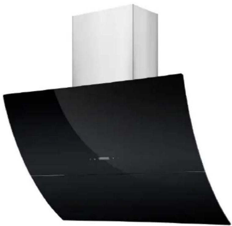
| Product type | Decorative hood |
| Energy efficiency class | C |
| Annual energy consumption | 88.7 kWh/year |
| Max airflow | 646.7 m³/h |
| Max pressure | 279 Pa |
| Noise level | 69 dB(A) |
| Number of speeds | 3 |
| Lighting | LED 2 x 1.5 W (non-replaceable) |
| Average illuminance | 55 lux |
| Control | Remote control included (CR2032 battery) |
| Grease filter | Metal, dishwasher-safe (monthly cleaning) |
| Charcoal filter | 2 included, replace annually |
| Timer | Yes, programmable automatic shut-off |
| Clock | Yes, LCD display |
| Power supply | 220-240 V ~ 50 Hz |
| Min height above hob | 70 cm (electric), 80 cm (gas) |
| Exhaust duct diameter | 150-153 mm |
| Operating modes | Extraction or recirculation |
| Standby function | Yes, automatic glass closure |
| Repairability | LED lamp not user-replaceable |
Frequently Asked Questions - CEHDI9750TCLCD CONTINENTAL EDISON
User questions about CEHDI9750TCLCD CONTINENTAL EDISON
0 question about this device. Answer the ones you know or ask your own.
Ask a new question about this device
Download the instructions for your Basket in PDF format for free! Find your manual CEHDI9750TCLCD - CONTINENTAL EDISON and take your electronic device back in hand. On this page are published all the documents necessary for the use of your device. CEHDI9750TCLCD by CONTINENTAL EDISON.
USER MANUAL CEHDI9750TCLCD CONTINENTAL EDISON
natural_image
Abstract geometric shapes with no text or symbolsContinental Edison
natural_image
Modern kitchen air conditioner with a white cabinet and black interior (no text or symbols visible)CEHDI9750TCLCD
Installation (Mode extraction).... 12
Installation (Mode recyclage)....14
text_image
27 4.5 2.5 *25.5 *33.5Unite:mm
natural_image
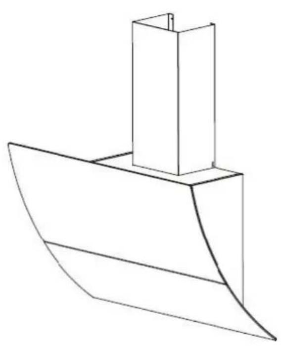
Line drawing of a boat hull with a rectangular structure on top (no text or symbols)Installation (Mode extraction)
natural_image
Diagram of airflow around a mechanical component with directional arrows indicating movement (no text or symbols)natural_image
Technical diagram showing a mechanical component with a spring and cylindrical part, no text or symbols presentInstallation (Mode recyclage)
natural_image
Diagram of a mechanical or fluid system with directional arrows and a central block, no text or symbols present.natural_image
Illustration of a hand holding an electrical plug with a cable, showing a right-hand rule for voltage or power (no text or symbols present)natural_image
Diagram of a brick wall with a pipe outlet and directional arrows indicating flow or movement (no text or symbols)text_image
Diagram illustrating a 3D geometric structure with labeled points and planes, likely from a physics or engineering context.natural_image
Diagram showing a mechanical component with a spring and cylindrical part, no text or symbols presentnatural_image
Technical line drawing of a cabinet with two views showing internal components and a side view of the cabinet (no text or symbols)natural_image
Two technical line drawings showing a tool inside a box and a hand holding a tool, both without any text or symbols.natural_image
Simple line drawing of a rectangular box and a small 3D box with internal lines, no text or symbols present.natural_image
Technical line drawing showing two views of a brick wall structure with a chimney and a cabinet, no text or symbols present.natural_image
Technical line drawing showing two views of a mechanical device with a tool inserted into a housing (no text or symbols)natural_image
Technical line drawing of an electric motor with visible blades and mounting flanges (no text or symbols)natural_image
Symbol of a trash bin with crossed lines indicating no waste or discharge, and a solid black rectangle below (no text or labels)Read this guide carefully before installing and using this product and keep it for future reference.
Read this guide and keep it
Thank you for choosing Continental Edison. This Use and Maintenance Guide is designed to provide you with all the necessary information regarding the installation, use and maintenance of the appliance.
In order to operate the unit properly and securely, read this user guide carefully before installing and using the product.
Contents
Find some informations.... 30
Important safety instructions....31
Lamp....37
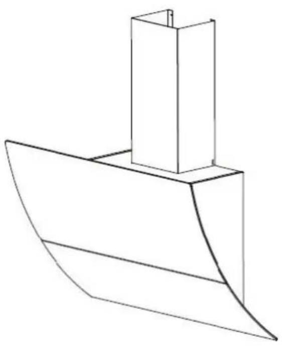
Product description.... 38
Description of the pieces....39
Installing the hood....40
Preparation before installation....40
Installation (Mode extraction)......40
Installation (Mode recyclage)......42
Fixing the hood to the wall....42
Cleaning....50
Touch control....51
Help....54
Technical informations....55
Further information....56
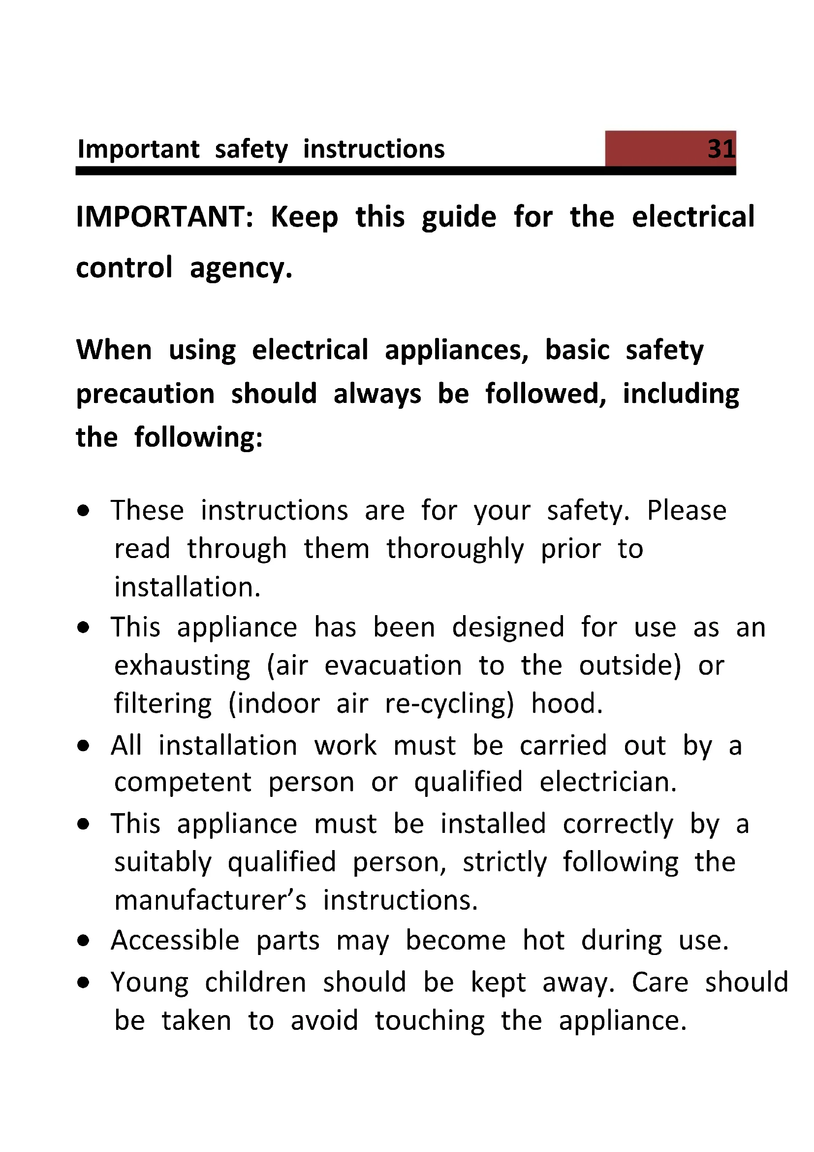
IMPORTANT: Keep this guide for the electrical control agency.
When using electrical appliances, basic safety precaution should always be followed, including the following:
- These instructions are for your safety. Please read through them thoroughly prior to installation.
- This appliance has been designed for use as an exhausting (air evacuation to the outside) or filtering (indoor air re-cycling) hood.
- All installation work must be carried out by a competent person or qualified electrician.
- This appliance must be installed correctly by a suitably qualified person, strictly following the manufacturer's instructions.
- Accessible parts may become hot during use.
-
Young children should be kept away. Care should be taken to avoid touching the appliance.
-
The Manufacturer highly recommends that this appliance be kept out of the reach of babies and small children.
- This appliance can be used by children aged from 8 years and above and persons with reduced physical, sensory or mental capabilities or lack of experience and knowledge if they have been given supervision or instruction concerning use of the appliance in a safe way and understand the hazards involved. Children shall not play with the appliance. Cleaning and user maintenance shall not be made by children without supervision.
-
Regularly check the power plug and power cord for damage. If the supply cord is damaged, it must be replaced by the manufacturer, its service agent or similarly qualified persons in order to avoid a hazard.
-
Do not allow the electric cables to touch the hot parts of the appliance.
- Make sure that the power cord is not caught under or in the appliance and avoid damage to the power cable.
- Do not use flammable sprays in close vicinity to the appliance.
- Please dispose of the packing material carefully.
- We also recommend that you pay special attention during use and during cleaning. Refer to the instructions in the "CLEANING" section.
-
A steam cleaner is not to be used.
-
Warning: When used for extraction, refer to the national regulations for building ventilation systems. Do not connect the exhaust pipe to a VMC type ventilation system, to a flue (chimney, boiler, ...). Also check the absence of disruption with the ventilation of the room when there are gas appliances (water heater, gas cooker, ...). If in doubt, use the hood in recycling mode.
- Proper ventilation of the room must be provided when the hood is used simultaneously with appliances using gas or other fuel.
-
The air must not be vented through a duct that used to vent flue gases from appliances burning gas or other fuels. The rules regarding the evacuation of the air must be respected.
-
Warning: The hood may stop working during an electrostatic discharge (e.g. lightning). This involves no risk of damage. Switch off the electricity supply to the hood and reconnect after one minute.
- To avoid the risk of fire, clean the metal filter regularly and closely watch and regulate pans containing hot oil.
- Do not use the hood if it shows signs of damage or imperfection. Contact customer services.
- Do not flame under the range hood.
-
When installing the appliance, make sure that the following distances between the top of cooker or hob and the lowest part of the cooker hood must be observed:
Gas hobs: 800mm.
Electric hobs: 700mm. -
Warning: Before connecting the hood: switch off the electricity supply and check that the supplied voltage and frequency coincide with that indicated on the appliance nameplate.
- Warning: There is a risk of electric shock and fire if cleaning is not carried out in accordance with the instructions.
- Warning: For safety reason, please use only the same size of fixing or mounting screw which are recommended in this instruction manual.
- Warning: Failure to install the screws or fixing device in accordance with these instructions may result in electrical hazards.
Electrical Shock Hazard
Only plug this unit into a properly earthed outlet. If in doubt seek advice from a suitably qualified engineer.
The available lamps and the correspondence ILCOS D codes and lamp pictures:
Use type lamp (or use in alternative type lamp) DSS-1.5-S-120 (ILCOS D code in according to standard IEC 61231).
- Non-replaceable LED lamp
- Max wattage: 1.5 W
- Voltage range: 12V
- Dimensions:
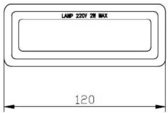
text_image
LAMP 220V 2ft MAX 120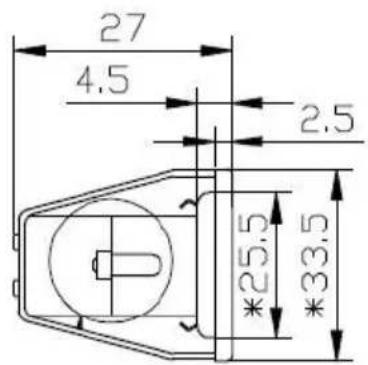
text_image
27 4.5 2.5 *25.5 *33.5Unit:mm
natural_image
Line drawing of a boat hull with a rectangular hull and triangular roof (no text or symbols)| Index | Description | Illustration | Quantity |
| PL-1 | Hood body | 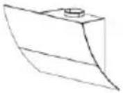 | 1 |
| PL-2 | Lower chimney (500mm) | 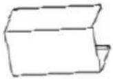 | 1 |
| PL-3 | Upper chimney (500mm) | 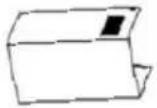 | 1 |
| PL-4 | Plastic pipe (Φ 150-153mm; 2 meter flexible tube) | 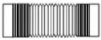 | 1 |
| PL-5 | Upper chimney bracket | 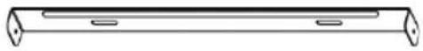 | 1 |
| PL-6 | Lower chimney bracket | 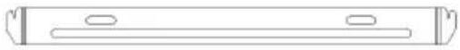 | 1 |
| PL-7 | Cooker hood bracket | 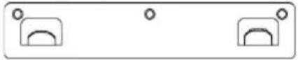 | 1 |
| PL-8 | Screw (ST4 * 8 mm) | 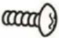 | 6 |
| PL-9 | Screw (ST4 * 30 mn) | 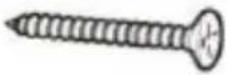 | 9 |
| PL-10 | Carbon filter | 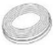 | 2 |
| PL-11 | Remote Control | 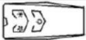 | 1 |
Preparation before installation

ATTENTION
Carefully remove the carton. Wear gloves to protect your hands from sharp edges.

ATTENTION
Remove the protective film from the product before putting it into service.
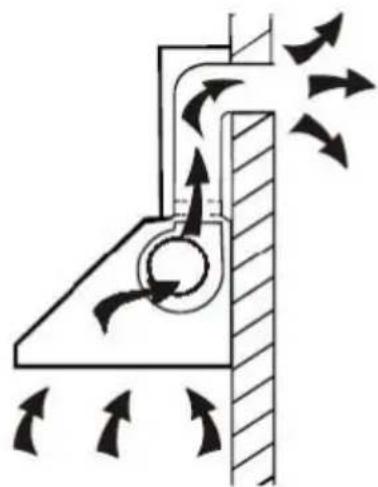
Installation (Mode extraction)
If the wall has an opening to the outside, your hood may be connected as shown in the diagram below
using the extraction duct provide or any suitable extraction condu for example a flexible aluminum sheath or constituted another non-flammable material with an inside diameter of less than 150mm.
natural_image
Diagram of airflow around a mechanical component with directional arrows indicating movement (no text or symbols)Duct Installation :
● Determine the exact installation position of the hood.
- Plan the path of the air exhaust of outward.
- Make sure that the duct path is a short and straight as possible. To allow optimal use, the duct must 2.50m long in total.
- The duct must lead directly to the outside, and must not lead to attic, a house, a garage or in an enclosed space.
- Duct accessories (elbows, fittings and adapters) would reduce the flow of air.
- Bent elbows and S-shaped profiles do not provide efficient air extraction, they are not recommended for using.
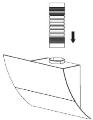
natural_image
Technical line drawing of a mechanical component with a cylindrical part and a spring-like element, showing a downward arrow (no text or symbols)Installation (Mode recyclage)
If you do not have an exit to the outside, the exhaust pipe is not required, and the installation procedures are the same as those described in the "Installation (Extraction Mode)" section.
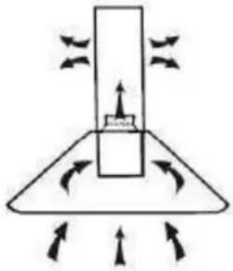
natural_image
Diagram of a mechanical or fluid system with directional arrows and a central block, no text or symbols present.Fixing the hood to the wall
Before installing, make sure the unit is not plugged into an electrical outlet.
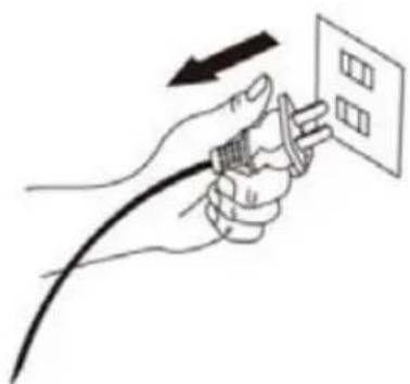
natural_image
Illustration of a hand holding a plug with a cable, pointing to a grid on a wall (no text or symbols)The hood should be placedleast 70cm above the cook .
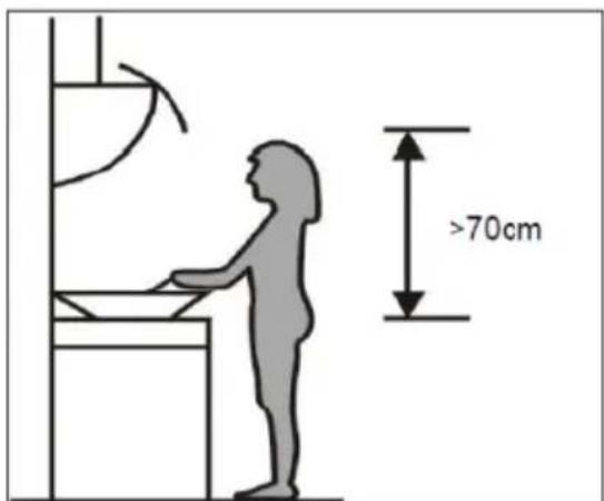
text_image
>70cmRecommendations for wall mounting
Do not make any changes to the unit or its mounting bracket on the wall!
Before installing the device, check the condition of the wall on which it will be fixed: the wall must be in good condition, it must not show any damage (cracks, sagging humidity, ...).
Do not drill a hole near old holes, even plugged It is imperative that you consult a building professional to use the anchoring system (screws, dowels, etc.)
appropriate to the material that constitutes your wall, as well as to the weight of the appliance. Observe the diameter of the fixing screws indicated in this manual.
Do not modify the holes for securing the unit or its mounting bracket to the wall.
Drill the wall with a drill of the appropriate size for the anchoring system. Remove debris and dust.
Regularly check the mounting points of the device on the wall. Tighten them if necessary.
Position the hood at the desired height respecting the minimum height above the hob.
Mark the location of the wall bracket.(placed the holes between 700 and 800 mm above the worktop)
Remove the hood and position the wall bracket to make the locations of the holes on the wall.
Drill the 3 holes in the wall to insert the appropriate fastening system (screw ST4x30mm).
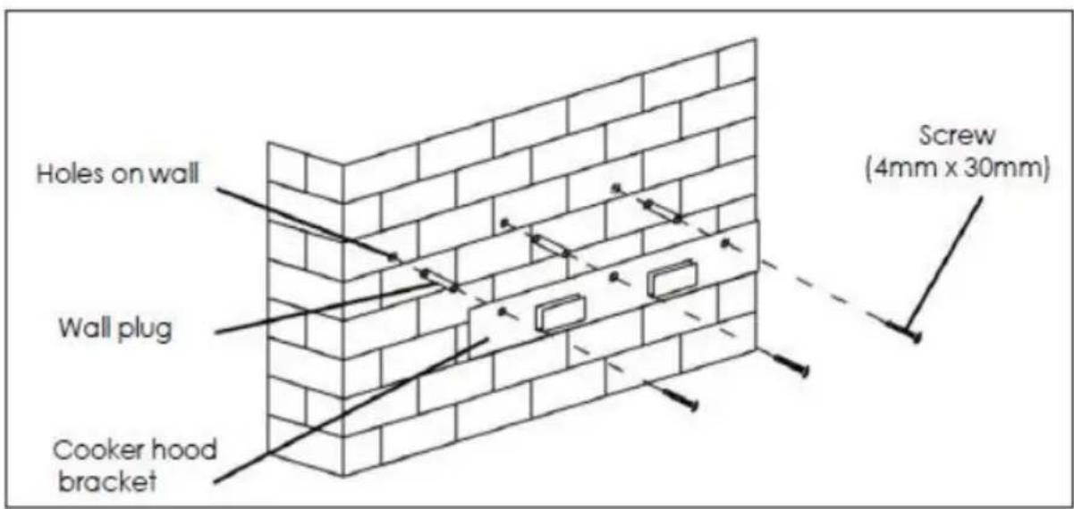
text_image
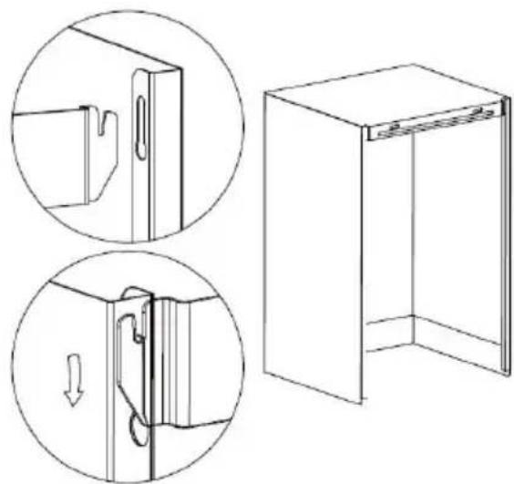
Holes on wall Wall plug Cooker hood bracket Screw (4mm x 30mm)Hang the hood in the notch of the wall bracket.
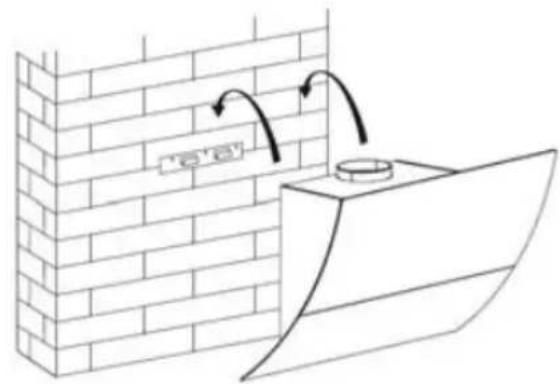
text_image
e'Once the hood is in place, locate the location of the additional wall mount screws as shown in the following diagram.
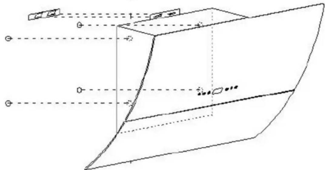
Remove the hood to puncture the wall and install wall plugs.
Secure the body of the hood with 4 screws of 4 mm diameter using dowels adapted to your wall.
natural_image
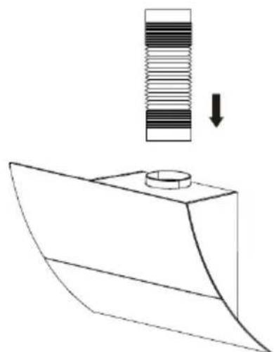
Pure geometric diagram of a 3D object with projection lines and control points, no text or symbols presentIf the extraction mode is selected, place the exhaust air duct on the a outlet as shown.
natural_image
Technical line drawing of a mechanical component with a spring and cylindrical part, no text or symbols presentAttach the lower chimney support to the lower chimney as shown.
natural_image
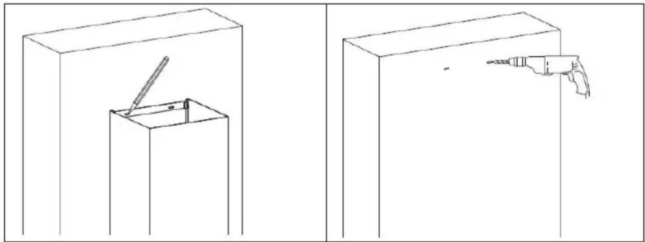
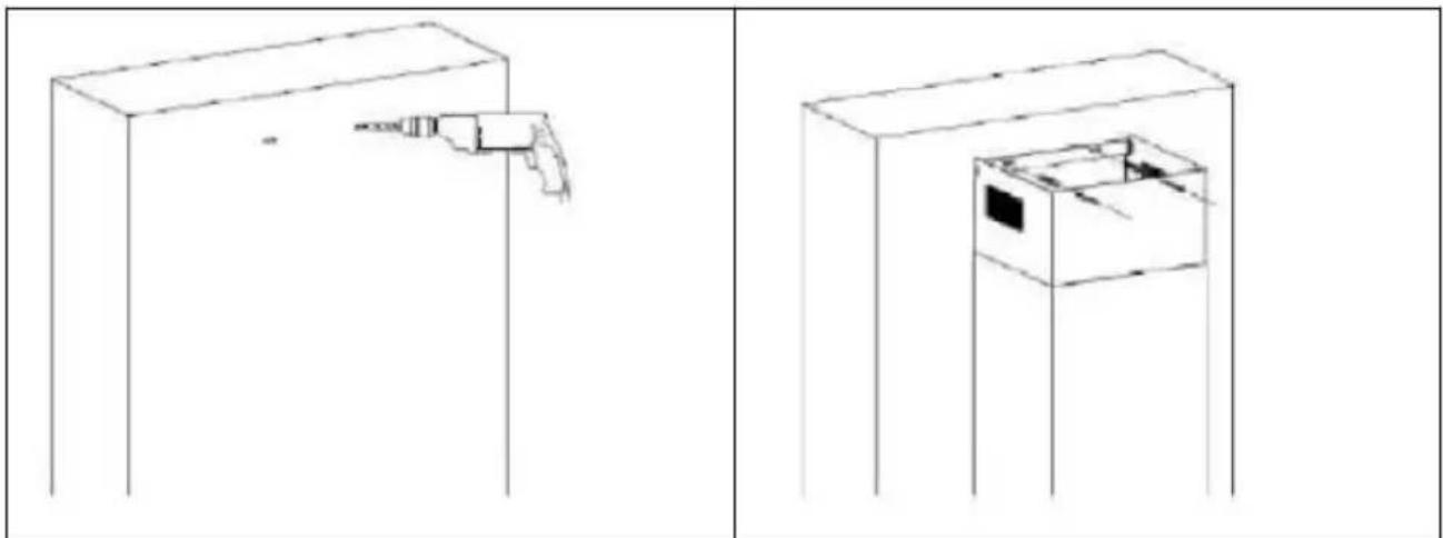
Technical line drawing showing two views of a door frame with internal components and a separate 3D view of the interior (no text or symbols)Install the lower chimney on the appliance, and mark the holes position on the wall.
Remove the lower chimney, then drill holes in the wall hole with diameter 4 mm screw.
natural_image
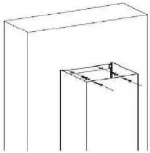
Two technical line drawings showing a tool inside a box and a drill bit emerging from a base, both without any text or symbols.Install the lower chimney on appliance again, then screw it to the wall with 2 screws of diameter 4 mm and the corresponding wall plugs (not supplied).
natural_image
Simple line drawing of a rectangular box and a cube with internal lines, no text or symbols presentFix the upper chimney bracket on the upper chimney by 2 screws of diameter 8 mm.
Pull the upper chimney upwards to the target height and mark the holes on the wall.
natural_image
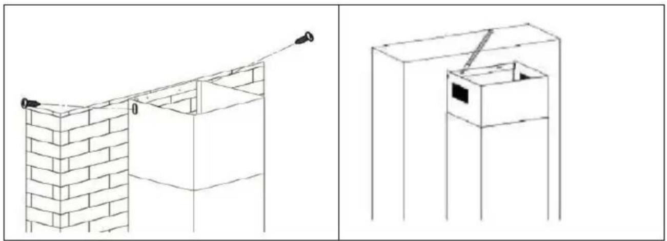
Two technical line drawings of a brick wall and a box structure, showing structural details without any text or symbols.Release the upper chimney and then drill holes on the wall.
Pull out the upper chimney again, then fix it to the w with 2 screws ST4x30mm.
natural_image
Two technical line drawings of a cabinet with a handle and internal compartments, shown from different angles (no text or symbols)Position the activated charcoal filter in the block and turn it clockwise. Do t same on the other side.
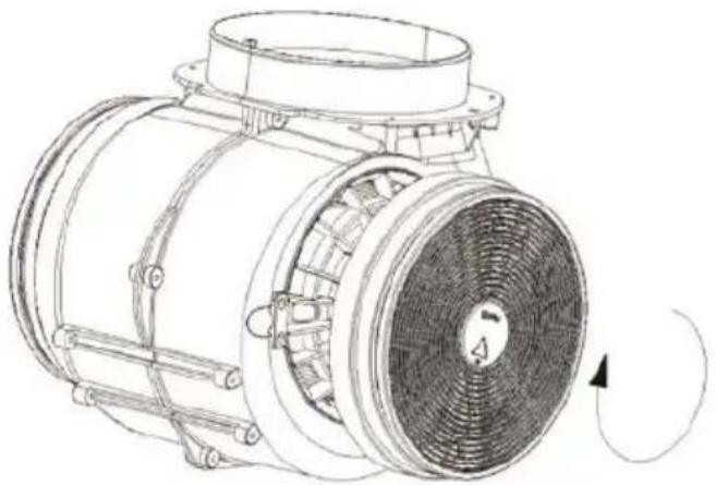
natural_image
Technical line drawing of a mechanical fan or motor assembly with no visible text or symbolsNOTE: Make sure the filter properly engaged. Otherwise, it could fall, which is dangerous. When the activated charcoal filter is switched on, the suction force drops.
Make sure the filters are properly engaged to prevent it from falling and may cause damage.
The carbon filters must be replaced at least once a year, or more often if used intensively.
Attention! Before cleaning switch the unit off and pull out the plug.
In standby mode, press for 3 seconds to open the window without turning on the suction or light.
To close the window, press for 3 seconds.
- Regular Cleaning
Use a soft cloth moistened with hand-warm mildly soapy water or household cleaning detergent. Never use metal pads, chemical, abrasive material or stiff brush to clean the unit.
• Monthly Cleaning for Grease Filter
ESSENTIAL: Clean the filter every month can prevent any risk of fire.
The filter collects grease, smoke and dust. It is directly affecting the efficiency of the cooker hood. If not cleaned, the grease residue (potential flammable) will saturate on the filter. Clean it with household cleaning detergent.
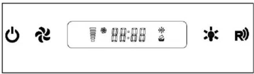
text_image
Control panel interface with icons for power, refresh, battery, and signal symbols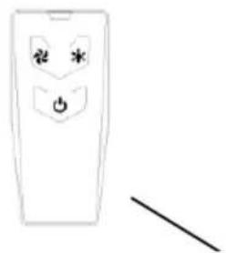
natural_image
Simple line drawing of a remote control panel with power button and antenna (no text or symbols)Remote control
Noted:
- Before using the remote control, please Remove the battery film!3V CR2032 battery included.
- Please abandon old batteries at battery collection points
STANDBY MODE
After plug in, only flashing slowly, system in STANDBY MODE.

"ON/OFF" Button:
In STANDBY MODE press the window will open.
The buttons and the display panel will light. The hood is ready to operate. By default, the hood is set to the minimum suction, lighting off. This is also valid when using the remote control.
When you turn the hood back on after first use, it will operate with the same settings previously used.
When the hood is in operation, when you press once, the suction will be stopped and the lighting will remain active. If you press and hold for 3 seconds, the hood will be in standby mode: suction, lights off and the window will close.

"FAN SPEED" Button:
Button to change the speed of the motor. 1 active support the low suction, a second medium suction and a third the maximum suction. If you press again, suction returns to the down position.

"Light" button
For lighting On & Off
CLOCK SETTING
In STANDBY MODE, press +& hold for1 second, the "88:88" flashing & enter the CLOCK SETTING MODE.
In this state:
pressing for changing selecting hour or minute
pressing key for decrease
pressing *key for increase
If press+ key or without any operation in CLOCK SETTING MODE for 5 seconds, will save automatically & exit CLOCK SETTING MODE.
TIMER SETTING
When motor is working, press +28& hold for1 second, display flashing shows "00:00", enter the TIMER SETTING MODE.
In this state:
Pressing for increase 15 minutes
pressing for decrease 1 minutes
pressing for increase 1 minute.
If press key or without no any operation in CLOCK SETTING MODE for 10 seconds, will save automatically start to count down, display shows the left time.
When time up, both motor & light will turn off automatically come back to STANDBY MODE(but the windows will not close)
LCD display
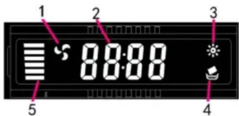
text_image
1 2 3 8:00 4 5- Motor symbol, will rotate when the motor is working
- Time display
- Light
- Cleaning symbol, appear when total working time up to 14 hours or at the first time using after plugging on the appliance
- Motor speed
| Fault | Cause | Solution |
| Light on, but fan does not work | The fan blade is jammed. | Switch of the unit and repair by qualified service personnel only. |
| The motor is damaged. | ||
| Fan do not work | light burn | Replace the lamp with correct rating. |
| Power cord looses. | Plug in to the power supply again | |
| Serious Vibration of the unit | The fan blade is jammed. | Switch of the unit and repair by qualified service personnel only. |
| The fan motor is not fixed tightly. | Switch of the unit and repair by qualified service personnel only. | |
| The unit is not hung properly on the bracket. | Take down the unit and check whether the bracket is in proper location. | |
| Weak power | The filter is dirty | Clean the filter |
ELECTRICAL CONNECTION DIAGRAM
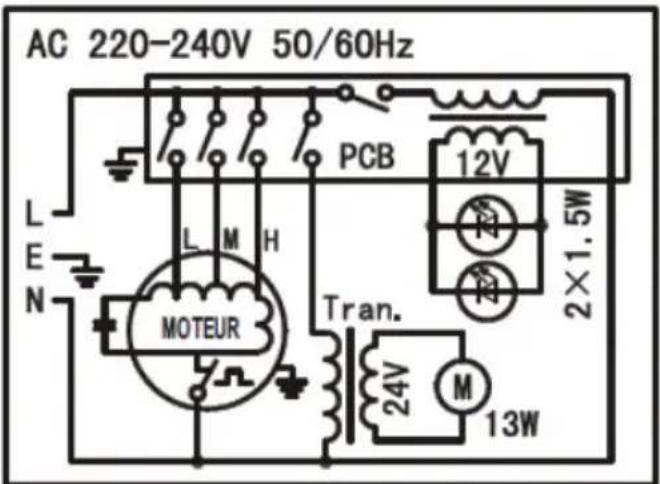
text_image
AC 220-240V 50/60Hz L E N PCB 12V M H 2×1.5W MOTEUR Tran. 24V M 13W| Symbol | Value | Unit | |
| Model identification | CEHDI9750TCLCD (HJ27017329) | ||
| Annual Energy Consumption | AEC_hotte | 88,7 | kWh/a |
| Energy Efficiency class | C | ||
| Time increase factor | f | 1,4 | |
| Fluid Dynamic Efficiency | FDE_hotte | 16,3 | |
| Fluid Dynamic Efficiency class | D | ||
| Energy Efficiency Index | EEI_hotte | 81,2 | |
| Measured air flow rate at best efficiency point | Q_BEP | 353,3 | m3/h |
| Measured air pressure at best efficient point | P_BEP | 279 | Pa |
| Maximum airflow | Q_max | 646,7 | m3/h |
| Measured electric power input at best efficiency point | W_BEP | 167,8 | W |
| Nominal power of thelighting system | W_L | 3,0 | W |
| Average illumination of the lighting system on thecooking surface | E_moyen | 55 | lux |
| Lighting Efficiency | LE_hotte | 18,3 | lux/W |
| Lighting efficiency class | C | ||
| Grease Filtering Efficiency | GFE_hotte | 46,5 | |
| Grease Filtering Efficiency class | F | ||
| Measured power consumption in standby mode | P_S | 0.39 | W |
| Sound power level | L_WA | 69 | dB |
The method of measurement and calculation of the above table is in accordance with Commission Regulation (EU) No 65/2014 and 66/2014
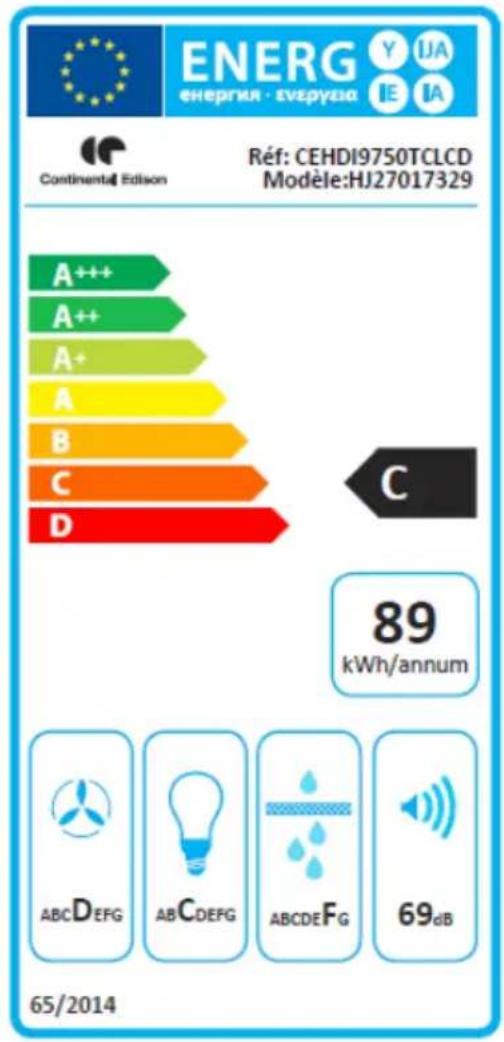
text_image
ENERG energia - svzpyzia Y IJA IE IA Continental Edison Réf: CEHDI9750TCLCD Modèle:HJ27017329 A+++ A++ A+ A B C D C 89 kWh/annum ABCDEFG ABCDEFG ABCDEFG 69dB 65/2014CONTINENTAL EDISON
120-126 quai de Bacalan
CS11584
33000 Bordeaux
Importé par A.M.C.
The following recommendations specify how to reduce the overall environmental impact of the cooking process.
(1) Install the range hood in a suitable location with good ventilation.
(2) Clean the cooker hood regularly so that nothing blocks the air.
(3) Do not forget to turn off the hood lamp once cooking is complete.
(4) Do not forget to turn off the range hood once cooking is complete.
Disassembly Information
Do not disassemble the unit in a manner that is not indicated in the operating instructions. This device must not be disassembled by the user. At the end of its life cycle, the appliance must not be disposed of with household waste. For recycling tips, please contact your local administration or dealer.
ENVIRONMENTAL PROTECTION
Electrical and electronic equipment is subject to selective collection.
Do not dispose of used electrical and electronic equipment with unsorted household waste; instead, take part in their selective collection.
It is for this reason that your appliance, as indicated by the symbol on its nameplate or on the packaging, must never be thrown in a public or private bin intended for household waste.
The user has the right to deposit the device in public collection places that selectively dispose of the waste to be recycled or reused for other applications.
The packaging is recyclable.
natural_image
Symbol of a trash bin with crossed lines indicating no waste or discharge, and a solid black rectangle below (no text or labels)