VE 4 S - Industrial vacuum cleaner TROTEC - Free user manual and instructions
Find the device manual for free VE 4 S TROTEC in PDF.
User questions about VE 4 S TROTEC
0 question about this device. Answer the ones you know or ask your own.
Ask a new question about this device
Download the instructions for your Industrial vacuum cleaner in PDF format for free! Find your manual VE 4 S - TROTEC and take your electronic device back in hand. On this page are published all the documents necessary for the use of your device. VE 4 S by TROTEC.
USER MANUAL VE 4 S TROTEC
natural_image
White multi-tube medical device with attached tubing and control panel (no visible text or symbols)Inhaltsübersicht
natural_image
Close-up of a black mechanical component with three white circular holes, labeled 'Abb. 3' (no other text or symbols)Safety Instructions ....B - 1
Scope of delivery ...... B - 1
Product description.....B - 1
Starting up ...... B - 2
Shutting down. B - 2
Cleaning and Maintenance ..... B - 2
Warning B-3
Fault Clearance.....B - 3
Technical Data B-3
List of Spare Parts. B - 3
Declaration of Conformity ..... B - 4
This publication replaces all previous publications. No part of this publication may be reproduced, processed using electronic systems, replicated or distributed in any form, without our written authorisation. Subject to technical changes. All rights reserved. Names of goods are used without guarantee of free usage and used for the most part according to the manufacturers' syntax. The names of goods used are registered and should be considered as such. We reserve the right to modify design in the interest of ongoing product improvement, such as shape and colour modifications. The scope of delivery may vary from that in the product description. All due care has been taken in compiling this document. We accept no liability for errors or omissions. © TROTEC®
Safety Instructions
Please read these instructions carefully before putting the unit into operation. The instructions are to be kept either in close proximity to the place where the unit is installed or near the actual unit itself. This unit was subjected to comprehensive material, functional and quality checks. Please remember, however, that there is still a risk of danger if this unit is not used by trained personnel or for purposes other than those stipulated in these instructions.
Please note the following instructions:
- The VE units are to be employed as overpressure and low pressure units; they are to be operated in a vertical position only and placed on all 4 buffers or wheels on a level surface. The units may not be used as a step or as a work surface or place for depositing items.
- Do not operate the units when the relative humidity is above 90% or in rain.
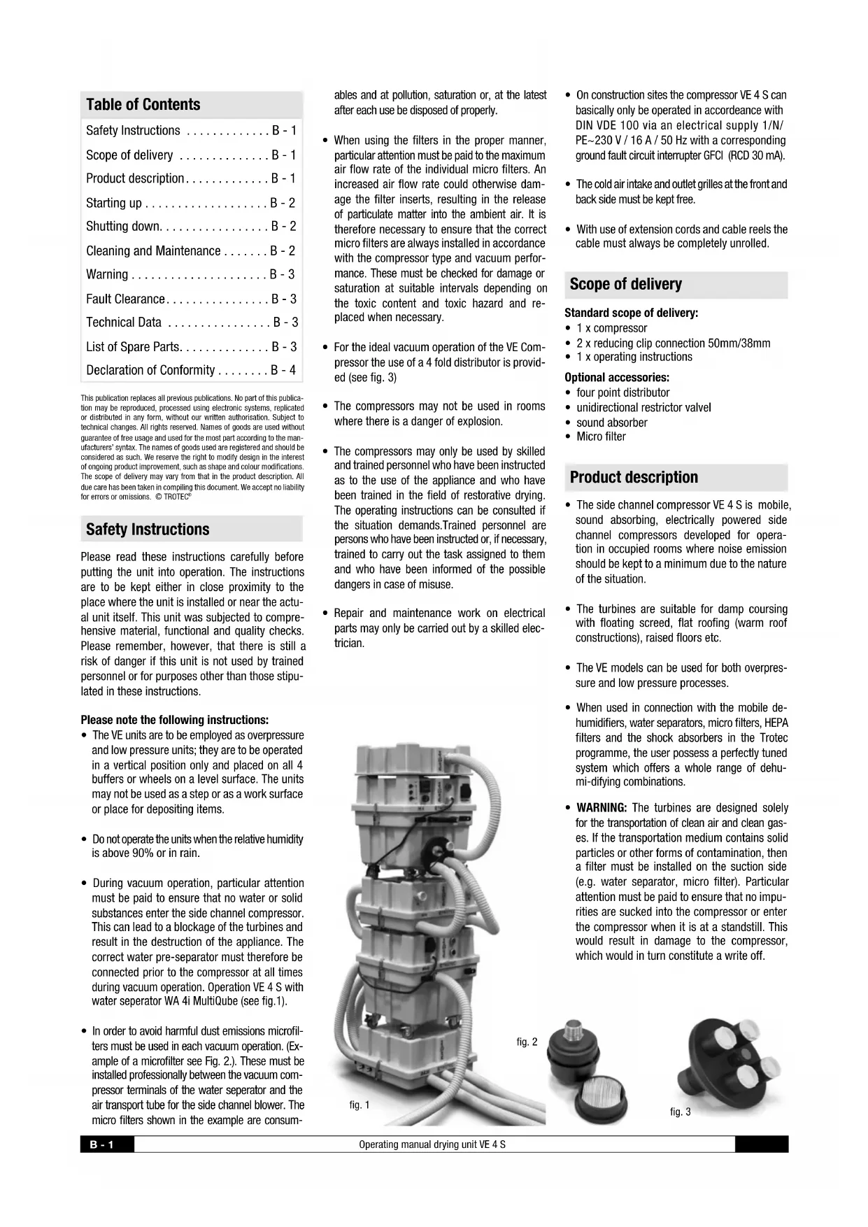
- During vacuum operation, particular attention must be paid to ensure that no water or solid substances enter the side channel compressor. This can lead to a blockage of the turbines and result in the destruction of the appliance. The correct water pre-separator must therefore be connected prior to the compressor at all times during vacuum operation. Operation VE 4 S with water separator WA 4i MultiQube (see fig.1).
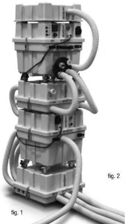
- In order to avoid harmful dust emissions microfilters must be used in each vacuum operation. (Example of a microfilter see Fig. 2.). These must be installed professionally between the vacuum compressor terminals of the water separator and the air transport tube for the side channel blower. The micro filters shown in the example are consum-
ables and at pollution, saturation or, at the latest after each use be disposed of properly.
- When using the filters in the proper manner, particular attention must be paid to the maximum air flow rate of the individual micro filters. An increased air flow rate could otherwise damage the filter inserts, resulting in the release of particulate matter into the ambient air. It is therefore necessary to ensure that the correct micro filters are always installed in accordance with the compressor type and vacuum performance. These must be checked for damage or saturation at suitable intervals depending on the toxic content and toxic hazard and replaced when necessary.
- For the ideal vacuum operation of the VE Compressor the use of a 4 fold distributor is provided (see fig. 3)
- The compressors may not be used in rooms where there is a danger of explosion.
- The compressors may only be used by skilled and trained personnel who have been instructed as to the use of the appliance and who have been trained in the field of restorative drying. The operating instructions can be consulted if the situation demands. Trained personnel are persons who have been instructed or, if necessary, trained to carry out the task assigned to them and who have been informed of the possible dangers in case of misuse.
- Repair and maintenance work on electrical parts may only be carried out by a skilled electrician.
natural_image
Mechanical device with coiled hoses and connectors, labeled 'fig. 1' and 'fig. 2' (no readable text or symbols on the device itself)- On construction sites the compressor VE 4 S can basically only be operated in accordance with DIN VDE 100 via an electrical supply 1/N/PE\~230 V / 16 A / 50 Hz with a corresponding ground fault circuit interrupter GFCI (RCD 30 mA).
- The cold air intake and outlet grilles at the front and back side must be kept free.
- With use of extension cords and cable reels the cable must always be completely unrolled.
Scope of delivery
Standard scope of delivery:
- 1 x compressor
- 2 x reducing clip connection 50mm/38mm
• 1 x operating instructions
Optional accessories:
- four point distributor
• unidirectional restrictor valvel - sound absorber
- Micro filter
Product description
- The side channel compressor VE 4 S is mobile, sound absorbing, electrically powered side channel compressors developed for operation in occupied rooms where noise emission should be kept to a minimum due to the nature of the situation.
- The turbines are suitable for damp coursing with floating screed, flat roofing (warm roof constructions), raised floors etc.
- The VE models can be used for both overpressure and low pressure processes.
- When used in connection with the mobile dehumidifiers, water separators, micro filters, HEPA filters and the shock absorbers in the Trotec programme, the user possess a perfectly tuned system which offers a whole range of dehumi-difying combinations.
- WARNING: The turbines are designed solely for the transportation of clean air and clean gases. If the transportation medium contains solid particles or other forms of contamination, then a filter must be installed on the suction side (e.g. water separator, micro filter). Particular attention must be paid to ensure that no impurities are sucked into the compressor or enter the compressor when it is at a standstill. This would result in damage to the compressor, which would in turn constitute a write off.
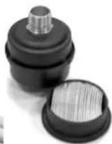
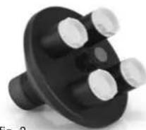
fig. 3
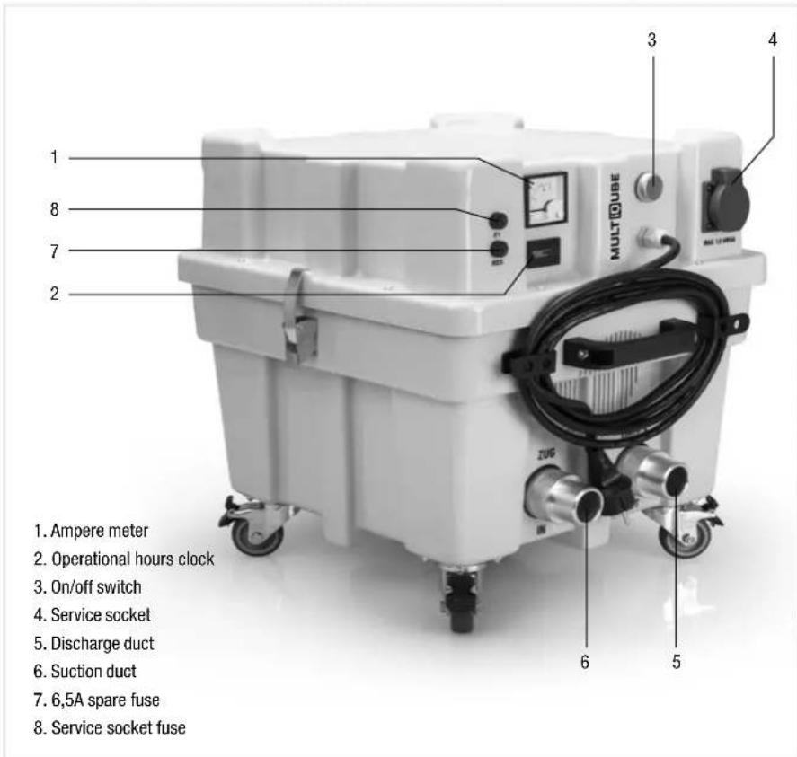
- The machines are equipped with an ampere meter to control the drying construction. The ideal air flow rate is displayed during running compressors in the lower third of the ampere meters. But particularly humid regions are characterized by higher flow resistances. The compressor can targeted these regions, and thus significantly shorten the drying time. Pay attention to the fact that the concentration of the entire compressor performance to a hole, operation in the higher ampere range can certainly be useful. That is how particularly high moisture concentrations are drawn quickly. The optimal number of exhaust ports and air vent openings can only be controlled if the DA 4 is open at all channels. Display values over 5 ampere shows an uneconomic operation, in which the compressor is not to be operated continuously.
- The device draws a peak current occasion of up to 16 A. The feed-in must be appropriately sized and fused.
- If problems occur in older buildings at operating the VE 4 S with blowing the fuse, we recommend the use of a starting current, which can be obtained from the Trotec range.
- The VE 4 S is equipped with a service socket (max. stress 6,3 A; 1\~230 V N / PE). The socket is protected by a safety fuse on the control panel.
- The air is suctioned in and discharged through a side channel compressor turbine.
Starting up
- When using a four point distributor (fig.4), please make sure that the yellow connecting stoppers, which are screwed into the distributor, are screwed on tight. Please screw on tightly if this is not the case. Only unscrew the necessary number of stoppers required for the dying process prior to starting up the unit.
- WARNING: When using a four point distributor, at least 1 air inlet must be opened during operation due to the power of the unit.
- The turbines of the VE series are special constructions with special performance boost, which have been optimized for insulation layer drying. Therefore, NEVER turn on the turbines with the connector plugs fully enclosed, as in this case, due to the enormous force that can warp drive shaft in the turbine housing, resulting in total damage. Each motor is tested before leaving the factory and delivered ready to run.
- Operating range/Limit range: Operating range: The ampere meter indicates values around 4 amperes.
Limit range: If values of more than 5 amperes are indicated, the installation has to be changed. Not an optimal compressor operation.
text_image
1 2 3 4 5 6 7 8 MULTOUBE ZUG Service socket Discharge duct Suction duct 6,5A spare fuse Service socket fuse 1. Ampere meter 2. Operational hours clock 3. On/off switch 4. Service socket 5. Discharge duct 6. Suction ductAt assemblies in the cross section, the air flow rate is not optimal. Under some circumstances, the turbine becomes so hot that the thermal protection is triggered. e.g. at elevated ambient temperatures.
- Therefore: create more relief openings to provide the pressure in the working area.
- Connect the compressor to the appropriate power supply. The unit is immediately ready for operation.
- Switch on the device with pushing the green Ein/Aus button.
Shutting down
- Press the ON/OFF switch.
- Wait until the motor stops running and the turbines don't turn anymore.
- Screw the stoppers which were removed before the unit was started up back into place and tighten accordingly.
- The motor must reach a complete standstill before it is switched on again, as this may otherwise result in a write-off.
Cleaning and maintenance
- Always remove the main plug from the main supply before carrying out cleaning and maintenance work.
- Remove the lid from the housing and clean with compressed air – not with water. If the housing of the unit has been cleaned with water, then the housing must be completely dry before the unit is installed.
- Please check all cables and plugs regularly for any signs of wear and tear or damage. Damaged cables or plugs must be replaced immediately.
- The turbines are special designs with specified performance curves and only suitable for the transportation of clean air and clean gases. If the transportation medium contains solid particles or other forms of contamination, then a filter must be installed on the suction side (e.g. water separator, micro filter).
- The bearings in the turbine are completely encased, maintenance-free, special high temperature bearings. The grease packing lasts a whole product life-time.
- Maintenance and repair should only be carried out by the firm Trotec.
Important information for recycling!
In the European Union electronic equipment must not be treated as domestic waste, but must be disposed of professionally in accordance with Directive 2002/96EU of the European Parliament and Council of 27 January 2003 concerning old electrical and electronic equipment. At the end of its life please dispose of this appliance in a manner appropriate to the relevant legal requirements.
Warning
- Suction side: Compressors in the VE-series generate a strong suction flow. Small objects and particles can be sucked in and cause injury. It is therefore necessary to ensure that no person is near the suction or discharge inlet when the compressor is in operation. When there are no pipes or hoses connected to the suction side, a protective grille has to be put in place. This grille is installed as standard when the Trotec side channel compressors are delivered. Particular attention must be paid to ensure that no impurities are sucked into the compressor or enter the compressor when it is at a standstill.
- Blow-out side: Compressors in the VE-series generate a strong discharge flow. Objects and particles that have been sucked in can shoot out at very high speeds and cause injury. This is why you should never place your hand in front of the discharge opening.
- Temperature at the turbine: When in operation, the temperature of the transport medium is transferred to the turbine housing and temperatures of over 50°C are reached within a short time. You should therefore never touch the turbine housing during operation and allow it to cool off.
Fault clearance
Not enough or no air at all is being suctioned in or blown out:
- Please check, whether the outside or outlet grille is dirty or clogged in the air ducts of the turbine (Coarse particle protection).
The motor isn't turning:
- Check if voltage is present
• Control the the electrical connections and hedges - Check to see if the thermal protection or the motor protection got triggered.
Service socket inoperative:
- Service socket safety fuse blown out due to overload. Switch off compressor and pull out mains plug. Unscrew fuse-box cover and replace defective fuse. Close cover properly and switch on unit again.
The motor switches off during operation:
The compressor worked outside it's operating range and over temperature protection switched off. This switch may have one of the following reasons:
- During pressure operation, back-pressure at the discharge side caused overheating.
- In suction operation drag in the suction line caused overheating.
- Wait until the motor has cooled off; switch the unit on again and monitor the ampere meter. Check the installation and make release holes to improve air circulation to allow the com-pressor to operate in the intended operating range.
- The units are dirty and the inlet grille are fouled or blocked. Wait until the compressor cooled down, disconnect the main plug, open the housing and clean grille and inside of housing. Re-assemble the housing.
Technical Data
Threshold value pressure side . . . . . . . 150 m³/h - at 200 mbar
Threshold value suction side .... 150 m³/h - at 175 mbar
Motor voltage .... 1 \~ 230 V / 50 Hz
Motor performance/motor current .. 1,1 kW / 7,5 A
Motor protection ..... thermocontact 120 °C
Mains fuse 16 A
Service socket fuse 6,3 A
Electric connection .... 4 m Kabel,
1 Schuko 2 pin plug .... 1\~230 V
List of spare parts
1).....cable with ground plug
2) ..... service socket 230V 16 A IP 44 ABL
3).....power relay 66.82.8.230
4) ....mounting clip 66.07
5) operational hours counter
6)...... complete module M22-AK10
7) . . . . . . . . . . switch M 22-DDL-GR-X1/X0
8) . . . . . . . miniature fuse 6,3 A normal-blow
9)..... miniature fuse 2 A normal-blow
10) fuse holder
11)....relay base incl. holder
12)....relay
13) . . . . . . . . . . . . . . . . . . . . . . . . . . . . . . . . . . . . . . . . . . . . . . . . . . . . . . . . . . . . . . . . . . . . . . . . . . . . . . . Optiflow-indicator VE 4
Declaration of Conformity
The Manufacturer:
Grebbener Straße 7
D-52525 Heinsberg
TROTEC
® GmbH & Co. KG
declares that the Side Channel Compressors have been built in accordance to the CE-directives for machine construction, as mentioned in subjoined standards.
Important Notice:
Any improper use, installation, servicing etc. or any alterations carried out by any other persons on the factory-made appliance render this declaration null and void.
Type of model:
Side Channel Compressor
Series:
VE 3 S, VE 4 S, VE 4, VE 6-230, VE6-400
Applicable regulations:
MA-RL 89/392/EWG Directive for machine construction: (98/37/EG)
Directive for low-voltage electrical installation: NS-RL (2006/95/EG)
EG-guideline for electrical compatibility (2004/108/EG)
WEEE (ElektroG) (2002/96/EG)
RoHS (2002/95/EG)
Signature product Management
Sommaire
natural_image
Close-up of a black mechanical component with three white circular holes (no text or symbols visible)photo 3
Dispositions applicables :
Directive relative aux machines 98/37/CEE