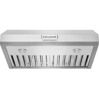
KVUC600KSS - Range hood KITCHENAID - Free user manual and instructions
Find the device manual for free KVUC600KSS KITCHENAID in PDF.



| Product Type | Range Hood |
| Brand | KitchenAid |
| Model | KVUC600KSS |
| Color | Stainless Steel |
| Width | 30 inches (76.2 cm) |
| Height | 7 inches (17.8 cm) |
| Power Supply | 120 V, 60 Hz, 463 W, 3.8 A |
| Vent Type | External (roof or wall) |
| Duct Diameter | Rectangular 3-1/4 x 10 inches (8.3 x 25.4 cm) |
| Fan Speeds | 4 speeds + Boost (5 minutes) |
| Lighting | 2 GU10 LED lights (6.5 W max), dimmable |
| Filters | 2 metal grease filters |
| Material | Stainless Steel |
| Controls | Push buttons |
| Special Features | Heat sensing (automatic activation), thermal protection |
| Installation | Wall mount or under cabinet |
| Included Accessories | Installation template, duct connector, screws, wall anchors |
| Weight | Approximately 15 kg (estimated) |
| Maintenance | Regular filter cleaning, LED light replacement |
Frequently Asked Questions - KVUC600KSS KITCHENAID
User questions about KVUC600KSS KITCHENAID
0 question about this device. Answer the ones you know or ask your own.
Ask a new question about this device
Download the instructions for your Range hood in PDF format for free! Find your manual KVUC600KSS - KITCHENAID and take your electronic device back in hand. On this page are published all the documents necessary for the use of your device. KVUC600KSS by KITCHENAID.
USER MANUAL KVUC600KSS KITCHENAID
30" (76.2 CM) AND 36" (91.4 CM) COMMERCIAL STYLE WALL-MOUNT RANGE HOOD
HOTTE À MONTAGE MURAL DE STYLE COMMERCIAL DE 30 PO (76,2 CM) ET 36 PO (91,4 CM)
CAMPANA PURIFICADA / EXTRACTORA, DE ESTILO COMERCIAL DE 30" (76,2 CM) Y 36" (91,4 CM)
Installation Instructions and Use and Care Guide Instructions d'installation et guide d'utilisation et d'entretien Instrucciones de instalacion y Manual de uso y cuidado
For questions about features, operation/performance, parts, accessories, or service, call: 1-800-422-1230
or visit our website at www.kitchenaid.com.
In Canada, for assistance, installation, and service, call: 1-800-807-6777
or visit our website at www.kitchenaid.ca.
Tools and Parts 4
Location Requirements 4
Venting Requirements 5
Electrical Requirements 6
INSTALLATION INSTRUCTIONS 7
Prepare Location 7
Install Range Hood 9
Make Electrical Connection 9
Install Vent Covers (Optional) 10
Complete Installation 10
RANGE HOOD USE 10
Range Hood Controls 10
RANGE HOOD CARE 11
Cleaning 11
WIRING DIAGRAM 12
ASSISTANCE OR SERVICE 13
In the U.S.A. 13
In Canada 13
SECURITE DE LA HOTTE 14
EXIGENCES D'INSTALLATION 16
ASSISTANCE OU DEPANNAGE 25
Aux E.-U. 25
Au Canada 25
Your safety and the safety of others are very important.
We have provided many important safety messages in this manual and on your appliance. Always read and obey all safety messages.

This is the safety alert symbol.
This symbol alerts you to potential hazards that can kill or hurt you and others.
All safety messages will follow the safety alert symbol and either the word "DANGER" or "WARNING."
These words mean:
ADANGER
WARNING
You can be killed or seriously injured if you don't immediately follow instructions.
You can be killed or seriously injured if you don't follow instructions.
All safety messages will tell you what the potential hazard is, tell you how to reduce the chance of injury, and tell you what can happen if the instructions are not followed.
IMPORTANT SAFETY INSTRUCTIONS
WARNING: TO REDUCE THE RISK OF FIRE, ELECTRIC SHOCK, OR INJURY TO PERSONS, OBSERVE THE FOLLOWING:
Use this unit only in the manner intended by the manufacturer. If you have questions, contact the manufacturer.
Before servicing or cleaning the unit, switch power off at service panel and lock the service disconnecting means to prevent power from being switched on accidentally. When the service disconnecting means cannot be locked, securely fasten a prominent warning device, such as a tag, to the service panel.
■ Installation work and electrical wiring must be done by qualified person(s) in accordance with all applicable codes and standards, including fire-rated construction.
- Do not operate any fan with a damaged cord or plug. Discard fan or return to an authorized service facility for examination and/or repair.
- Sufficient air is needed for proper combustion and exhausting of gases through the flue (chimney) of fuel burning equipment to prevent backdrafting. Follow the heating equipment manufacturer's guideline and safety standards such as those published by the National Fire Protection Association (NFPA), the American Society for Heating, Refrigeration and Air Conditioning Engineers (ASHRAE), and the local code authorities.
- When cutting or drilling into wall or ceiling, do not damage electrical wiring and other hidden utilities.
Ducted fans must always be vented outdoors.
CAUTION: For general ventilating use only. Do not use to exhaust hazardous or explosive materials and vapors.
CAUTION: To reduce risk of fire and to properly exhaust air, be sure to duct air outside - do not vent exhaust air into spaces within walls or ceilings, attics or into crawl spaces, or garages.
WARNING: TO REDUCE THE RISK OF FIRE, USE ONLY METAL DUCTWORK.
WARNING: TO REDUCE THE RISK OF A RANGE TOP GREASE FIRE:
- Never leave surface units unattended at high settings. Boilovers cause smoking and greasy spillovers that may ignite. Heat oils slowly on low or medium settings.
Always turn hood ON when cooking at high heat or when flambeing food (i.e. Crepes Suzette, Cherries Jubilee, Peppercorn Beef Flambé).
Clean ventilating fans frequently. Grease should not be allowed to accumulate on fan or filter.
Use proper pan size. Always use cookware appropriate for the size of the surface element.
WARNING: TO REDUCE THE RISK OF INJURY TO PERSONS IN THE EVENT OF A RANGE TOP GREASE FIRE, OBSERVE THE FOLLOWING:a
SMOTHER FLAMES with a close fitting lid, cookie sheet, or metal tray, then turn off the burner. BE CAREFUL TO PREVENT BURNS. If the flames do not go out immediately, EVACUATE AND CALL THE FIRE DEPARTMENT.
NEVER PICK UP A FLAMING PAN - you may be burned.
DO NOT USE WATER, including wet dishcloths or towels - a violent steam explosion will result.
Use an extinguisher ONLY if:
- You know you have a class ABC extinguisher, and you already know how to operate it.
- The fire is small and contained in the area where it started.
- The fire department is being called.
- You can fight the fire with your back to an exit.
^a Based on "Kitchen Fire Safety Tips" published by NFPA.
WARNING: To reduce the risk of fire or electrical shock, do not use this fan with any solid-state speed control device.
READ AND SAVE THESE INSTRUCTIONS
INSTALLATION REQUIREMENTS
Tools and Parts
Gather the required tools and parts before starting installation. Read and follow the instructions provided with any tools listed here.
NOTE: This range hood is recommended for use with cooking surfaces with a maximum total rating of 75,000 BTUs or less for 30^ (76.2 cm) range hood and 90,000 BTUs or less for 36^ (91.4 cm) range hood.
Tools needed
Level
■ Drill with 1/4'' (3.0 cm), 3/16'' (4.8 mm), 1/8'' (3.0 mm), and 5/16'' (7.9 mm) drill bits
Pencil
Wire stripper or utility knife
Tape measure or ruler
Pliers
Caulking gun and weatherproof caulking compound
Vent clamps
Jigsaw or keyhole saw
Flat-blade screwdriver
Metal snips
Phillips screwdriver
Metric hex key set
Parts needed
Home power supply cable
1/2" (1.3 cm) UL listed or CSA approved strain relief
3 UL listed wire connectors
1 wall or roof cap
Metal vent system
Chimney cover (optional)
Masking Tape
Parts supplied
Remove parts from packages. Check that all parts are included.
- Range hood assembly with ventilator and light bulbs installed
3/4" x 10" (8.3 cm x 25.4 cm) rectangular vent connector
2 metal grease filters for 30^ (76.2 cm) model
3 metal grease filters for 36^ (91.4 cm) model
T20 Torx*adapters
4-5x45mmmounting screws
6-4.5 x 13 mm screws
3-4x8mm screws
4-10x50wallanchors
Installation template WALL 30" and 36" models
Installation template CABINET 30" and 36" models
Location Requirements
IMPORTANT: Observe all governing codes and ordinances. Have a qualified technician install the range hood. It is the installer's responsibility to comply with installation clearances specified on the model/serial rating plate. The model/serial rating plate is located behind the left fiiter on the rear wall of the vent hood.
Range hood location should be away from strong draft areas, such as windows, doors, and strong heating vents.
Cabinet opening dimensions that are shown must be used. Given dimensions provide minimum clearance.
Grounded electrical outlet is required. See the "Electrical Requirements" section.
The Range hood is factory set for venting through the roof or wall.
All openings in ceiling and wall where Range hood will be installed must be sealed.
For Mobile Home Installations
The installation of this range hood must conform to the Manufactured Home Construction Safety Standards, Title 24 CFR, Part 328 (formerly the Federal Standard for Mobile Home Construction and Safety, Title 24, HUD, Part 280) or when such standard is not applicable, the standard for Manufactured Home Installation 1982 (Manufactured Home Sites, Communities and Setups) ANSI A225.1/NFPA 501A, or latest edition, or with local codes.
Product Dimensions
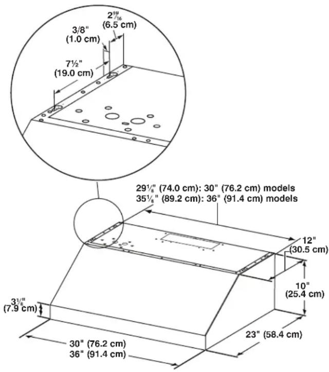
Front View
TORX and T20 are registered trademarks of Acument Intellectual Properties, LLC.
Back View
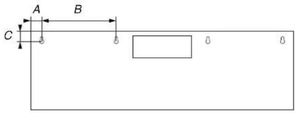
Back view 30" (76.2 cm) 36" (91.4 cm)
| A | \( {1}^{1}/{}_{8}^{\prime \prime }\left( {{2.9}\mathrm{\;{cm}}}\right) 1 \) | \( {1}^{1}/{}_{8}^{\prime \prime }\left( {{2.9}\mathrm{\;{cm}}}\right) \) |
| B 7" (17.8 cm) 9 | \( {7}_{8}^{\prime \prime } \) (25 cm) | |
| C 5/8" (1.6 cm) \( 5/{8}^{\prime \prime }\left( {{1.6}\mathrm{\;{cm}}}\right) \) | ||
Top View
Top view 30^ (76.2 cm) 36" (91.4 cm)
| A | \( {12}^{3}/{16}^{\prime \prime }\left( {{31}\mathrm{\;{cm}}}\right) {15.2}^{\prime \prime }\left( {{38.6}\mathrm{\;{cm}}}\right) \) |
| B | \( 7/8''\left( {{20}\mathrm{\;{cm}}}\right) 7\;7/8''\left( {{20}\mathrm{\;{cm}}}\right) \) |
Optional Full-Width Chimney Cover Installations
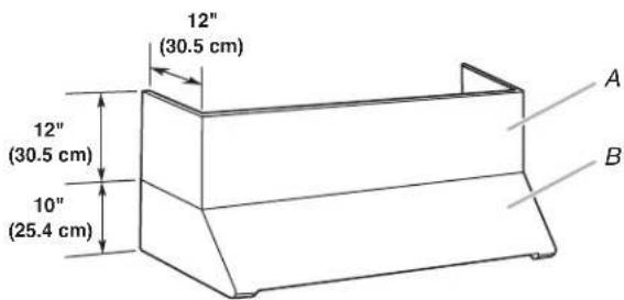
A. Optional full-width chimney cover
B. Range hood
Cabinet Dimensions
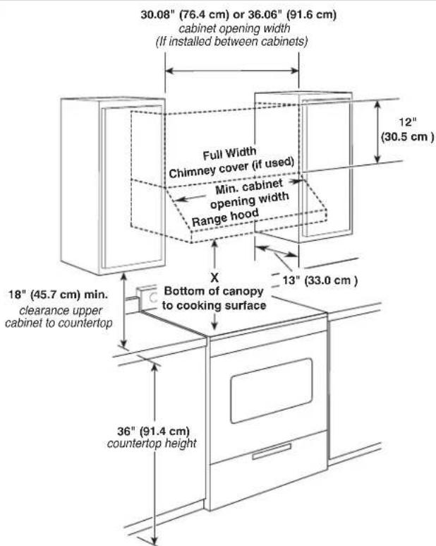
IMPORTANT: Minimum distance "X": 24" (61.0 cm) to electric cooking surface and 30" (76.2 cm) to gas cooking surface.
Suggested maximum distance "X": 36 (91.4 cm).
Venting Requirements
Vent system must terminate to the outdoors.
- Do not terminate the vent system in an attic or other enclosed area.
Do not use a 4^ (10.2 cm) laundry-type wall cap.
Use metal vent only. Rigid metal vent is recommended.
The length of vent system and number of elbows should be kept to a minimum to provide efficiient performance.
For the most efficient and quiet operation:
Use no more than three 90^ elbows.
Make sure there is a minimum of 24^ (61.0 cm) of straight vent between the elbows if more than one elbow is used.
Do not install two elbows together.
Use clamps to seal all joints in the vent system.
The vent system must have a damper. If roof or wall cap has a damper, do not use damper supplied with the range hood.
Use caulking to seal exterior wall or roof opening around the cap.
The size of the vent should be uniform.
Cold Weather Installations
An additional back draft damper should be installed to minimize backward cold air flow and a thermal break should be installed to minimize conduction of outside temperatures as part of the vent system. The damper should be on the cold air side of the thermal break.
The break should be as close as possible to where the vent system enters the heated portion of the house.
Makeup Air
Local building codes may require the use of makeup air systems when using ventilation systems greater than specified CFM of air movement. The specified CFM varies from locale to locale. Consult your HVAC professional for specific requirements in your area.
Venting Methods
This range hood is factory set for venting through the roof or wall.
A 3^1 / 4^ × 10^ (8.3× 25.4cm) rectangular vent system is needed for installation (not included). The hood exhaust opening is 3^1 / 4^ × 10^ (8.3× 25.4cm) . Vent system can terminate either through the roof or wall. To vent out of the top of the range hood and through a wall, a 90^ elbow is needed. See "Install Range Hood" section for details for installing the damper.
NOTE: Flexible vent is not recommended. Flexible vent creates back pressure and air turbulence that gently reduce performance.
Rear discharge
This range hood can be vented directly out the back using the 3^1/4 × 10 (8.3 cm × 25.4 cm) rectangular damper (supplied) along with a 3^1/4 × 10 (8.3 cm × 25.4 cm) rectangular vent system (not supplied). See "Install Range Hood" section for details for installing the damper.
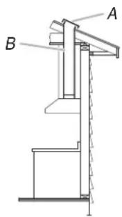
Roof Venting
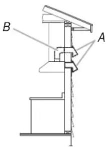
Wall Venting (top or rear discharge)
A. Roof cap
B. 3^1 / 4 × 10^5 (8.3 x 25.4 cm) rectangular metal vent
A. Wall cap
B. 3^ / 4^ × 10^ (8.3 x 25.4 cm) rectangular metal vent
Calculating Vent System Length
To calculate the length of the system you need, add the equivalent feet (meters) for each vent piece used in the system.
3^1 / 4^ × 10^ (8.3× 25.4cm) Vent System
Vent Piece
| 31/4" x 10" (8.3 cm x 25.4 cm)90° elbow | 5.0 ft(1.5 m) |
| 31/4" x 10" (8.3 x 25.4 cm)fl at elbow | 12.0 ft(3.7 m) |
| 31/4" x 10" (8.3 x 25.4 cm)wall cap | 0.0 ft(0.0 m) |
Example vent system
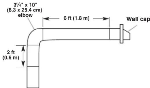
Maximum Recommended Length = 35 ft (10.7m)
1-90° elbow = 5.0 ft (1.5 m)
8 ft (2.4m) straight = 8.0 ft (2.4m)
1 - wall cap = 0.0 ft (0.0 m)
Length of system 3^1 / 4^ × 10^ = 13.0 ft (3.9 m)
(8.3 cm × 25.4 cm)
Electrical Requirements
Observe all governing codes and ordinances.
Ensure that the electrical installation is adequate and in conformance with National Electrical Code, ANSI/NFPA 70 (latest edition), or CSA Standards C22.1-94, Canadian Electrical Code, Part 1 and C22.2 No. 0-M91 (latest edition) and all local codes and ordinances.
If codes permit and a separate ground wire is used, it is recommended that a qualifi ed electrician determine that the ground path is adequate.
A copy of the above code standards can be obtained from:
National Fire Protection Association
1 Batterymarch Park
Quincy, MA 02169-7471
CSA International
8501 East Pleasant Valley Road
Cleveland, OH 44131-5575
A 120V 463 W, 60 Hz, AC only, 3.8 A, fused electrical circuit is required.
If the house has aluminum wiring, follow the procedure below:
Connect the aluminum wiring using special connectors and/or tools designed and UL listed for joining copper to aluminum.
Follow the electrical connector manufacturer's recommended procedure. Aluminum/copper connection must conform with local codes and industry accepted wiring practices.
- Wire sizes and connections must conform with the rating of the appliance as specified on the model/serial rating plate. The model/serial plate is located behind the fi Iter on the rear wall of the range hood.
Wire sizes must conform to the requirements of the National Electrical Code, ANSI/NFPA 70 (latest edition), or CSA Standards C22.1-94, Canadian Electrical Code, Part 1 and C22.2 No. 0-M91 (latest edition) and all local codes and ordinances.
INSTALLATION INSTRUCTIONS
Prepare Location
It is recommended that the vent system be installed before hood is installed.
If you are installing a full width duct cover, follow the instructions included with that product.
Before making cutouts, make sure there is proper clearance within the ceiling or wall for exhaust vent.
Check your ceiling height and the hood height maximum before you select your hood.
- Disconnect power.
- Determine which venting method to use: roof or wall.
- Select a flat surface for assembling the range hood. Place covering over that surface.
WARNING
Excessive Weight Hazard
Use two or more people to move and install range hood.
Failure to do so can result in back or other injury.
- Using two or more people, lift range hood onto covered surface.
NOTE: This range hood can be mounted to the cabinets or to the wall.
For Cabinet Installations
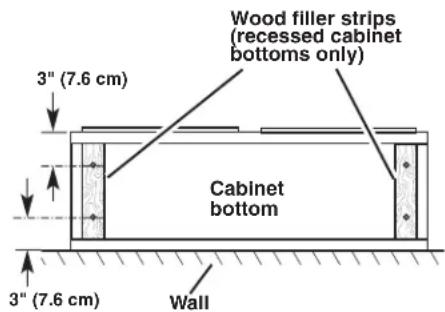
If cabinet has recessed bottom, add wood fi Ier strips on each side. Install screws to attach fi Ier strips in locations shown.
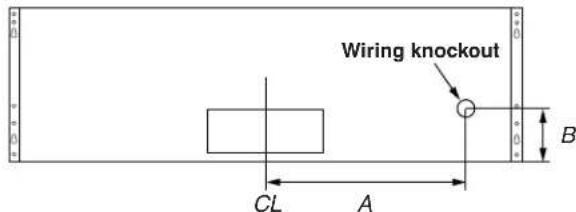
Determine Wiring Hole Location
Cut only one 114 (3.2 cm) diameter wiring access hole. See Step 2 for wiring hole location instructions.
- Determine and clearly mark a vertical centerline on the wall and cabinet in the area the vent opening will be made.
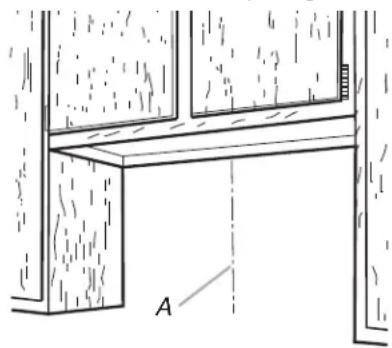
A. Centerline
- To wire through top:
Mark a line distance "A" from the left of the centerline on the underside of the cabinet. Mark the point on this line that is 7^ / 8'' (20.0 cm) from back wall. Drill a 1^ / 4'' (3.2 cm) diameter hole through the cabinet at this point.
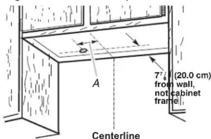
A. 127^15 (31.0 cm)
Cut Openings for 3^1 / 4^ × 10^ (8.3 cm x 25.4 cm) Rectangular Vent System
Roof Venting
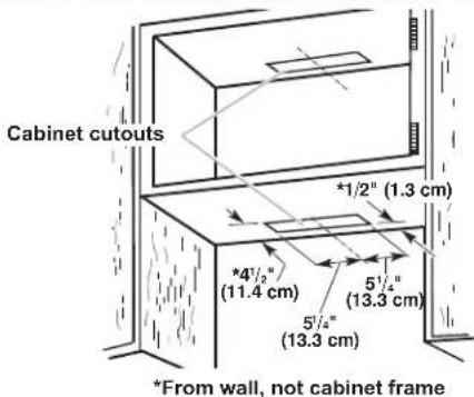
To make a 4^ × 10^1/2 (10.2 cm × 26.7 cm) rectangular cutout on the underside of cabinet top and bottom:
- Mark lines 1/2 (1.3 cm) and 4 12 (11.4 cm) from the back wall on the centerline of the underside of cabinet.
- Mark lines 5^1 / 4 (13.3 cm) to the right and left of the centerline on the underside of cabinet.
-
Use saber or keyhole saw to cut a rectangular opening for vent.
-
Repeat steps 1-3 for the underside of the top of the cabinet.
Wall Venting Under Cabinet
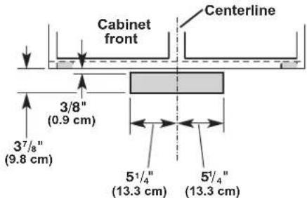
To make a 3^1/2× 10^1/2 (8.9 cm x 26.7 cm) rectangle in the wall:
- Make two lines by measuring 3 / 8'' (9.5 mm) and 3^ / 8^ (9.8 cm) down from underside of cabinet and mark on the centerline on the back wall.
- Mark lines 5^1/4 (13.3 cm) to the right and left of the centerline on the wall.
Use saber or keyhole saw to cut a rectangular opening in the wall for the vent.
For Wall Installations:
- Determine and mark the centerline on the wall where the range hood will be installed. Follow the same centerline and mark on in the bottom of cabinet.
- Select a mounting height between a minimum of 24" (61.0 cm) for electric cooking surfaces and 30" (76.2 cm) for gas cooking surfaces. The suggested maximum height is 36" (91.4 cm) above the range to the bottom of the hood. Mark a horizontal reference line on the wall.
- Tape templates in place, aligning the WALL template centerline and bottom of template with hood bottom line and with the centerline marked on the wall.
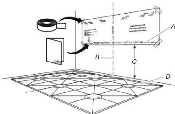
A. Horizontal reference line
B. Vertical centerline
C. Mounting height
D. Cooking surface
- Mark centers of the fastener locations through the templates to the wall and to the cabinet. Then remove the templates.
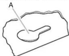
A. Keyhole slot
IMPORTANT: All screws must be installed into wood. If there is no wood to screw into, additional wall framing supports may be required.
- Drill 3/16" (4.8 mm) pilot holes at all locations where screws are being installed into wood.
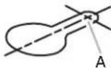
A. Drill pilot hole
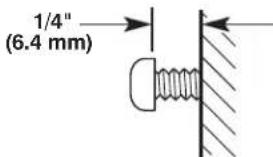
- Install the 4 - 5 × 45 mm mounting screws. Leave a 1/4" (6.4 mm) gap between the wall and the back of the screw head to slide range hood into place.
- Determine and make all necessary cuts in the wall or ceiling for the vent system. Install the vent system before installing the hood. See "Venting Requirements" section.
Complete Preparation
- Determine the required height for the home power supply cable and drill a 1 / 4'' (3.2 cm) hole at this location.
- Run the home power supply cable according to the National Electrical Code or CSA Standards and local codes and ordinances. There must be enough 1/2'' (1.3 cm) conduit and wires from the fused disconnect (or circuit breaker) box to make the connection in the hood's electrical terminal box.
NOTE: Do not reconnect power until installation is complete.
- Remove terminal box cover and set aside.
- Remove knockout from the top of the vent hood and install a UL listed or CSA approved 1/2'' (1.3 cm) strain relief.
Install Range Hood
- Depending on your installation, remove either top or rear rectangular vent knockout.
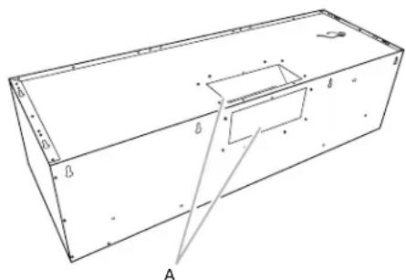
A. Vent knockouts
- Remove tape from damper fl ap.
NOTE: The 3^1 / 4'' × 10'' (8.3 x 25.4 cm) rectangular damper can be installed up to 1" (2.5 cm) on either side of the hood center to accommodate off center duct work.
- Attach the 3^1/4× 10^n(8.3× 25.4cm) rectangular vent connector to the range hood using sheet metal screws.
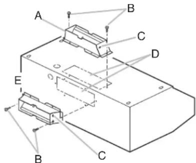
A. Top venting
B. Sheet metal screws
C. Hinge pin
D. Vent knockouts
E. Rear venting
NOTE: If the wall cap is directly behind the 3^1 / 4'' × 10'' (8.3 x 25.4 cm) rectangular vent connector, check that the damper and the wall cap do not interfere with each other. Remove the damper from the 3^1 / 4'' × 10'' (8.3 x 25.4 cm) rectangular vent connector if they interfere.
- Using two or more people, lift the hood into final position. Feed enough electrical wire through the 1/2'' (12.7 mm) UL listed or CSA approved strain relief to make connections in the terminal box. Tighten the strain relief screws.
- Position the range hood so that the large end of the keyhole slots are over the mounting screws. Then push the hood toward the wall (for cabinet mounting) or allow the range hood to slide down to the marked mounting height (for wall mounting) so that the screws are in the neck of the slots. Tighten the mounting screws, making sure the screws are in the narrow neck of slots. (For wall mount, check that the hood is level).
- Connect ventwork to hood. Seal joints with clamps to make secure and airtight.
- Check that back draft dampers work properly.
Make Electrical Connection
WARNING

Electrical Shock Hazard
Disconnect power before servicing.
Replace all parts and panels before operating.
Failure to do so can result in death or electrical shock.
- Disconnect power.
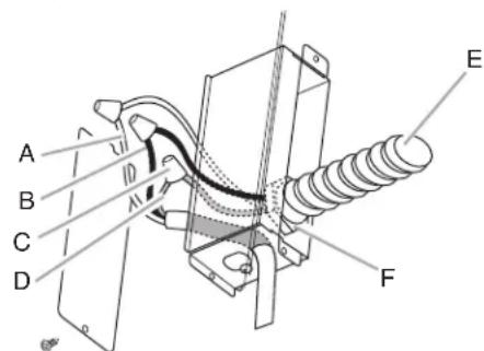
A. White wires
B. Black wires
C. UL listed wire connector
D. Green (or bare) and yellow-green ground wire
E. Home power supply cable
F. UL listed or CSA approved 1/2 (1.3 cm) strain relief
- Use UL listed wire connectors and connect white wires (A) together.
- Use UL listed wire connectors and connect black wires (B) together.
WARNING

Electrical Shock Hazard
Electrically ground blower.
Connect ground wire to green and yellow ground wire in terminal box.
Failure to do so can result in death or electrical shock.
- Connect green (or bare) ground wire from home power supply to yellow-green ground wire (C) in terminal box using UL listed wire connectors.
- Install terminal box cover.
- Check that all light bulbs are secure in their sockets.
- Reconnect power.
Install Vent Covers (Optional)
If you are installing an optional full width duct cover, follow the instructions included with that product.
Complete Installation
- Install metal grease filters. See the "Range Hood Care" section.
- Check the operation of the range hood blower and light. See the "Range Hood Use" section.
NOTE: To get the most efficient use from your new range hood, read the "Range Hood Use" section.
RANGE HOOD USE
The range hood is designed to remove smoke, cooking vapors, and odors from the cooktop area. For best results, start the hood before cooking and allow it to operate several minutes after the cooking is complete to clear all smoke and odors from the kitchen.

A. Fan speed control
B. Fan boost level
C. Light intensity control
Range Hood Controls
Operating the Light
- Press the light control buttons (C) to turn on and control the light settings.
- To select a lower intensity, press the left of the two light control buttons until desired light setting. To increase, press the right button.
Operating the Fan
- Press the fan speed control buttons (A) to turn on and control the fan settings.
- To boost the fan speed for five minutes, press the Fan Boost level button (B). Once the fi ve minutes have passed, the fan will return to the previously selected speed.
Auto On Fan
The range hood has a built in sensor to automatically turn the fan on when excessive heat is detected. If needed, the sensor will turn the fan to the Boost setting, and once the heat decreases, the fan will automatically turn off.
Thermal Protector
If the range hood shuts off while in use, press OFF button to turn off the range hood. Wait approximately 60 minutes, then press ON to restart the range hood.
The range hood is equipped with a thermal protector to avoid overheating conditions.
RANGE HOOD CARE
Cleaning
IMPORTANT: Clean the hood and grease filters frequently according to the following instructions. Replace grease fi Iters before operating hood.
Exterior Surfaces:
To avoid damage to the exterior surface, do not use steel wool or soap-fi Iled scouring pads.
Always wipe dry to avoid water marks.
Cleaning Method:
Liquid detergent soap and water, or all-purpose cleanser.
Wipe with damp soft cloth or nonabrasive sponge, then rinse with clean water and wipe dry.
Metal Grease Filter
To Remove Metal Grease Filters:
- Use two hands to remove the metal grease filters. Grasp fi ler handles, push toward the rear of the range hood, and pull down on the front handle to remove.
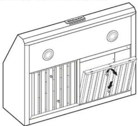
- Repeat for each grease filter.
- Grease filters should be cleaned using warm water, dishwashing liquid, and a non abrasive brush. Dishwasher not recommended.
To Reinstall Metal Grease Filters:
- Grasp filter handles and place rear of filter into rear track.
- Push down on the rear handle and set the front of the grease filter into the front track to secure.
- Repeat for each filter.
Replacing a LED lamp
Turn off the range hood and allow the LED bulb to cool. To avoid damage or decreasing the life of the new lamp, do not touch lamp with bare fingers. Replace lamp, using tissue or wearing cotton gloves to handle bulb.
If new lamps do not operate, make sure the lamps are inserted correctly before calling service.
- Disconnect power.
- Push up on the lens and turn it counterclockwise.
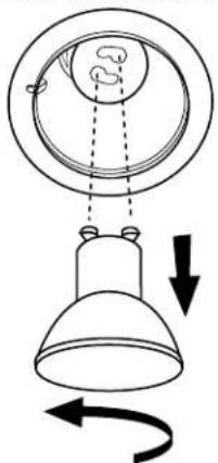
- Remove the lamp and replace it with a 120 V, 6.5 W maximum LED bulb with a GU10 base. Turn it clockwise to lock it into place.
- Repeat steps 2-3 for the other bulb if needed.
- Reconnect power.
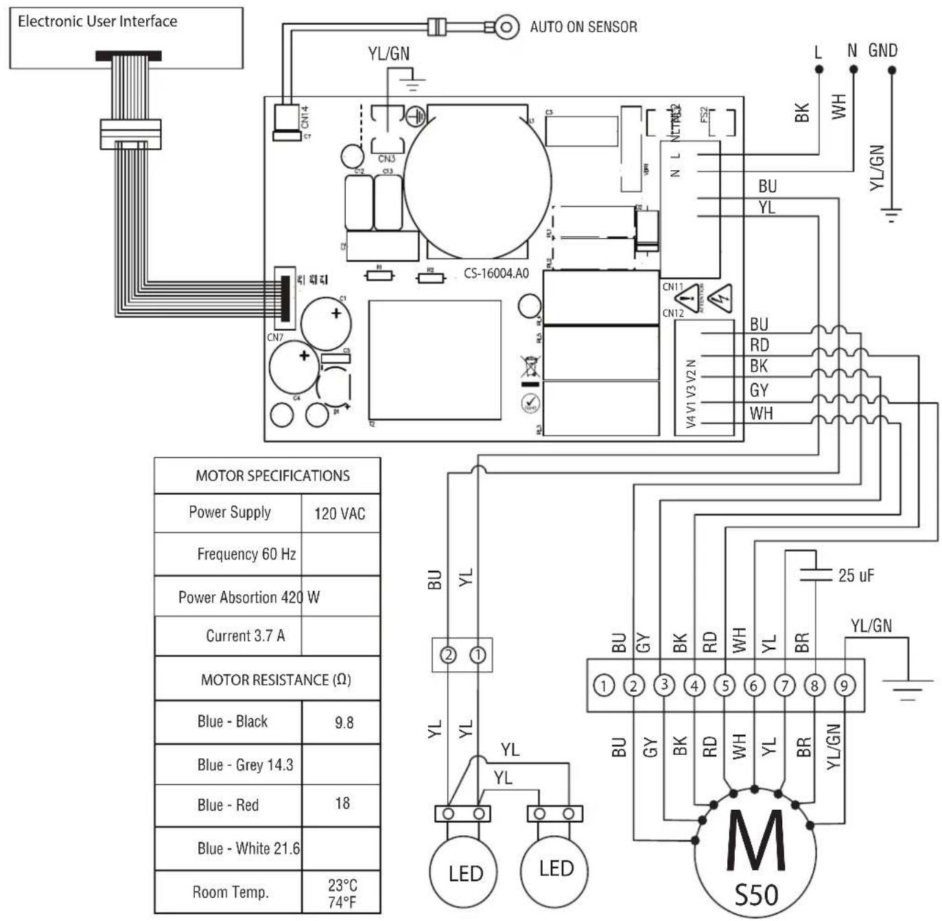
WIRING DIAGRAM
ASSISTANCE OR SERVICE
When calling for assistance or service, please know the purchase date and the complete model and serial number of your appliance. This information will help us to better respond to your request.
If you need replacement parts
If you need to order replacement parts, we recommend that you use only factory specified parts. Factory specified parts will fit right and work right because they are made with the same precision used to build every new appliance. To locate factory specified replacement parts in your area, call us or your nearest designated service center.
In the U.S.A.
If you have any problems or questions, call KitchenAid at 1-800-422-1230.
Our consultants provide assistance with:
Features and specifications on our full line of appliances.
Installation information.
Use and maintenance procedures.
■ Accessory and repair parts sales.
Specialized customer assistance (Spanish speaking, hearing impaired, limited vision, etc.).
Referrals to local dealers, repair parts distributors and service companies. KitchenAid designated service technicians are trained to fulfil the product warranty and provide afterwarranty service, anywhere in the United States.
To locate the KitchenAid designated service company in your area, you can also look in your telephone directory Yellow Pages.
For further assistance:
If you need further assistance, you can write to KitchenAid with any questions or concerns at:
KitchenAid Brand Home Appliances
Customer eXperience Center
553 Benson Road
Benton Harbor, MI 49022-2692
Please include a daytime phone number in your correspondence.
In Canada
Call the KitchenAid Canada Customer eXperience Centre toll free: 1-800-807-6777.
Our consultants provide assistance with:
Features and specifications on our full line of appliances.
Use and maintenance procedures.
■ Accessory and repair parts sales.
Referrals to local dealers, repair parts distributors and service companies. KitchenAid Canada designated service technicians are trained to fulfi II the product warranty and provide after-warranty service, anywhere in Canada.
For further assistance:
If you need further assistance, you can write to KitchenAid Canada with any questions or concerns at:
KitchenAid Brand Home Appliances
Customer eXperience Centre
200-6750 Century Ave.
Mississauga, Ontario L5N 0B7
Please include a daytime phone number in your correspondence.
SECURITE DE LA HOTTE
National Fire Protection Association
1 Batterymarch Park
Quincy, MA 02169-7471
CSA International
8501 East Pleasant Valley Road
Cleveland, OH 44131-5575
KitchenAid Brand Home Appliances
Customer eXperience Center
553 Benson Road
Benton Harbor, MI 49022-2692
KitchenAid Brand Home Appliances
Customer eXperience Centre
200-6750 Century Ave.
National Fire Protection Association
1 Batterymarch Park
Quincy, MA 02169-7471
CSA International
8501 East Pleasant Valley Road
Cleveland, OH 44131-5575
Se necessita un circuito eletrico de 120V 463 W, 60 Hz, CA solamente, protegado con fusible de 3,8 A.

- 30" (76.2 CM) AND 36" (91.4 CM) COMMERCIAL STYLE WALL-MOUNT RANGE HOOD
- HOTTE À MONTAGE MURAL DE STYLE COMMERCIAL DE 30 PO (76,2 CM) ET 36 PO (91,4 CM)
- CAMPANA PURIFICADA / EXTRACTORA, DE ESTILO COMERCIAL DE 30" (76,2 CM) Y 36" (91,4 CM)
- Your safety and the safety of others are very important.
- ADANGER
- WARNING
- IMPORTANT SAFETY INSTRUCTIONS
- READ AND SAVE THESE INSTRUCTIONS
- INSTALLATION REQUIREMENTS
- Tools and Parts
- Tools needed
- Parts needed
- Parts supplied
- Location Requirements
- For Mobile Home Installations
- Product Dimensions
- Back View
- Top View
- Optional Full-Width Chimney Cover Installations
- Cabinet Dimensions
- Venting Requirements
- For the most efficient and quiet operation:
- Cold Weather Installations
- Makeup Air
- Venting Methods
- Rear discharge
- Calculating Vent System Length
- / 4^ × 10^ (8.3× 25.4cm) Vent System
- Example vent system
- Maximum Recommended Length = 35 ft (10.7m)
- Electrical Requirements
- INSTALLATION INSTRUCTIONS
- Prepare Location
- Excessive Weight Hazard
- For Cabinet Installations
- Determine Wiring Hole Location
- Cut Openings for 31 / 4^ × 10^ (8.3 cm x 25.4 cm) Rectangular Vent System
- Roof Venting
- Wall Venting Under Cabinet
- For Wall Installations:
- Complete Preparation
- Install Range Hood
- Make Electrical Connection
- Install Vent Covers (Optional)
- Complete Installation
- RANGE HOOD USE
- Range Hood Controls
- Operating the Light
- Operating the Fan
- Auto On Fan
- Thermal Protector
- RANGE HOOD CARE
- Cleaning
- Exterior Surfaces:
- Cleaning Method:
- Metal Grease Filter
- To Remove Metal Grease Filters:
- To Reinstall Metal Grease Filters:
- Replacing a LED lamp
- ASSISTANCE OR SERVICE
- If you need replacement parts
- In the U.S.A.
- Our consultants provide assistance with:
- For further assistance:
- In Canada
- SECURITE DE LA HOTTE
Brand : KITCHENAID
Model : KVUC600KSS
Category : Range hood