
MAD50P1AWS - Dehumidifier MIDEA - Free user manual and instructions
Find the device manual for free MAD50P1AWS MIDEA in PDF.
| Product Type | Dehumidifier |
| Brand | Midea |
| Model | MAD50P1AWS |
| Extraction Capacity | Up to 50 pints/day (23.6 L/day) |
| Tank Volume | Approximately 6.5 L |
| Power Supply | 115-120 V ~ 60 Hz |
| Refrigerant | R32 (flammable) |
| Pump Type | Yes (model with pump) |
| Connectivity | Wi-Fi (2.4 GHz) via SmartHome app |
| Operating Modes | Normal dehumidification, continuous, turbo, comfort |
| Timer | Programmable On/Off from 0 to 24 h |
| Adjustable Humidity Level | 35% to 85% RH in 5% increments |
| Operating Temperature Range | 5°C to 32°C |
| Auto Defrost | Yes |
| Auto Shut-off | Tank full, tank removed, or humidity reached |
| Compressor Protection | 3-minute delayed start |
| Air Filter | Washable, clean every 2 weeks |
| Continuous Drainage | Possible with hose (ID 5/16", not included) |
| Included Accessories | Pump drain hose, cord loop |
| Warranty | 1-year limited (parts and labor) |
| Regular Maintenance | Clean filter, tank, and grille |
| Safety | Grounding required, refrigerant leak protection |
| Certifications | FCC, IC, Compliant with Part 15 |
| Recommended Use | Indoor domestic, room up to 50 m² (estimate) |
Frequently Asked Questions - MAD50P1AWS MIDEA
User questions about MAD50P1AWS MIDEA
0 question about this device. Answer the ones you know or ask your own.
Ask a new question about this device
Download the instructions for your Dehumidifier in PDF format for free! Find your manual MAD50P1AWS - MIDEA and take your electronic device back in hand. On this page are published all the documents necessary for the use of your device. MAD50P1AWS by MIDEA.
USER MANUAL MAD50P1AWS MIDEA
natural_image
Line drawing of a refrigerant appliance with lid and door (no text or symbols)DEHUMIDIFIER
MDP
USER MANUAL
MAD22C1AWS
MAD35C1AWS
MAD50C1AWS
MAD50P1AWS
OWNER'S MANUAL
SAFETY PRECAUTIONS 03
UNIT SPECIFICATIONS AND FEATURES 12
OPERATING INSTRUCTIONS 13
INSTALLATION INSTRUCTIONS 19
CARE AND CLEANING 20
TROUBLESHOOTING TIPS 21
APP INSTRUCTIONS 22
WARRANTY AND RETURN POLICY 28
Read This Manual
Inside you will find many helpful hints on how to use and maintain your dehumidifier properly. Just a little preventive care on your part can save you a great deal of time and money over the life of your dehumidifier. You'll find many answers to common problems in the troubleshooting tips - you should be able to fix most of them quickly before calling service. These instructions may not cover every possible condition of use, so common sense and care for safety is required when installing, operating and maintaining this product.

CAUTION
- Contact an authorized service technician for repair or maintenance of this unit.
- The unit is not designed to be used by young children or people with reduced physical, sensory or mental capabilities without supervision.
- Young children should be supervised to ensure that they do not play with the unit.
- If the power cord needs to be replaced, please contact our consumer service or an authorized technician.
- Electrical installation, if needed, must be performed in accordance to national regulation standards by qualified personnel only.
SAFETY PRECAUTIONS
Read safety precautions before installing or operating. To prevent death or injury to the user or other people and property damage, the following instructions must be followed. Incorrect operation due to ignoring of instructions may cause death, harm or damage.
Explanation of Symbols

WARNING
The signal word indicates a hazard with a medium level of risk which, if not avoided, may result in death or serious injury.

CAUTION
The signal word indicates a hazard with a low degree of risk which, if not avoided, may result in minor or moderate injury.

WARNING
Do not exceed the rating of the power outlet or connection device.
- Do not operate or stop the unit by switching on or off the power.
- Do not use an unspecified or damaged power cord.
- Do not modify power cord length or share the outlet with other appliances.
- Do not insert or pull out plug with wet hands.
- Do not install the appliance in a location that may be exposed to combustible gas.
- Do not place the unit near a heat source.
- Disconnect the power if strange sounds, smell, or smoke comes from the dehumidifier.
- Do not disassemble or attempt to repair the dehumidifier. Take it to an authorized service centre.
- Before cleaning, turn off the power and unplug the unit.
- Do not use the machine near flammable gas or combustibles, such as gasoline, benzene, thinner, etc.
- Do not drink or use the water drained from the unit.
- Do not take the water bucket out during operation.
- Do not use the unit in small spaces, such as a closet.
- Do not put in places where water may splash onto the unit.
- Place the unit on a level, sturdy section of the floor.
- Do not cover the intake or exhaust openings with cloths or towels.
- Care should be taken when using the unit in a room with the following persons: infants, children, elderly people, and people not sensitive to humidity.
- Do not use in areas where chemicals are handled.
- Never insert your finger or other foreign objects into grills or openings. Take special care to warn children of these dangers.
- Do not place heavy object on the power cord, and take care that the cord is not compressed.
- Do not climb up on or sit on the unit.
• Always insert the filters securely. Clean filter once every two weeks.
- If water enters the unit, turn the unit off and disconnect the power; contact a qualified service technician.
- Do not place flower vases or other water containers on top of the unit.
- Do not use extension cords.

CAUTION
- This appliance is not intended for use by persons (including children) with reduced physical, sensory or mental capabilities or lack of experience and knowledge, unless they have been given supervision or instruction concerning use of the appliance by a person responsible for their safety.
Children should be supervised to ensure that they do not play with the appliance.
- If the supply cord is damaged, it must be replaced by the manufacturer, its service agent or similarly qualified persons in order to avoid a hazard.
- Prior to cleaning or other maintenance, the appliance must be disconnected from the supply mains.
- Do not install the appliance in a location that may be exposed to combustible gas. If combustible gas accumulates around the unit, it may cause a fire.
- If the appliance is knocked over during use, turn off the unit and unplug it from the main power supply immediately. Visually inspect the unit to ensure there is no damage. If you suspect the unit has been damaged, contact a technician or customer service for assistance.
Our product must not be used in a water-damaged environment.
- In a thunderstorm, the unit must be unplugged to avoid damage to the machine due to lightning.
- Do not run cord under carpeting. Do not cover cord with throw rugs, runners, or similar coverings. Do not route cord under furniture or appliances. Arrange cord away from traffic area and where it will not be tripped over.
- Do not operate unit with a damaged cord or plug.
Discard unit or return to an authorized service facility for examination and/or repair.
- To reduce the risk of fire or electric shock, do not use this fan with any solid-state speed control device.
The appliance shall be installed in accordance with national wiring regulations.
Contact the authorised service technician for repair or maintenance of this unit.
Turn off the product when not in use.
- The manufacturer's nameplate is located on the panel of the unit and contains electrical and other technical data specific to this unit.
- Be sure the unit is properly grounded. To minimize shock and fire hazards, proper grounding is important.
- The power cord is equipped with a three-prong grounding plug for protection against shock hazards.
- Your unit must be used in a properly grounded wall receptacle. If the wall receptacle you intend to use is not adequately grounded or protected by a time delay fuse or circuit breaker (please refer to the nameplate for the electrical data), have a qualified electrician install the proper receptacle.
- Do not operate your air conditioner in a wet room such as a bathroom or laundry room.
- The unit's circuit board (PCB) is designed with a fuse to provide overcurrent protection. Specifications of the fuse are printed on the circuit board, such as: T 3.15A/250V (or 350V), etc.
Electronic Work

WARNING:
BEFORE PERFORMING ANY ELECTRICAL OR WIRING WORK, TURN OFF THE MAIN POWER TO THE SYSTEM.
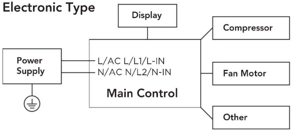
flowchart
graph TD
    A["Power Supply"] --> B["L/AC L/L1/L-IN N/AC N/L2/N-IN Main Control"]
    C["Display"] --> B
    D["Compressor"] --> B
    E["Fan Motor"] --> B
    F["Other"] --> B
NOTE: Please strictly follow the wiring label attached to the machine for all wiring connections. The wiring diagram may vary for different unit. Please refer to the wiring diagram on the machine you have purchased.
The above wiring diagram is a simplified version for preliminary illustration purposes only.
SAFETY MANUAL
FOR R32 REFRIGERANT MODEL
NOTE: This section is intended for certified technicians authorized to remove, discharge, handle and dispose of HFC refrigerants. Do not handle refrigerants without the proper training and certifications necessary in your area.
North America Products

CAUTION:
Risk of fire
flammable materials
IMPORTANT NOTE: Read this manual carefully before installing or operating your new appliance unit. Make sure to save this manual for future reference.
Explanation of symbols displayed on the unit
 | CAUTION | This symbol shows that the operation manual should be read carefully. |
 | CAUTION | This symbol shows that a service personnel should be handling this equipment with reference to the installation manual. |
 | CAUTION | This symbol shows that information is available such as the operating manual or installation manual. |
WARNING
- Servicing shall only be performed as recommended by the equipment manufacturer. Maintenance and repair requiring the assistance of other skilled personnel shall be carried out under the supervision of the person competent in the use of flammable refrigerants.
- DO NOT modify the length of the power cord or use an extension cord to power the unit.
- DO NOT share a single outlet with other electrical appliances. Improper power supply can cause fire or electric shock.
- Please follow the instructions carefully to handle, install, clean, or service the appliance to avoid any damage or hazard.
WARNING
- Flammable refrigerant R32 is used within appliance.
- When maintaining or disposing of the appliance, the refrigerant (R32) shall be recovered properly and shall not be discharged to the air directly.
- Compliance with national gas regulations shall be observed.
- Keep ventilation openings clear of obstructions.
- The appliance shall be stored so as to prevent mechanical damage from occurring.
- The appliance shall be stored in a well-ventilated area.
- Any person who is involved with working on or breaking into a refrigerant circuit should hold a current valid certificate from an industry-accredited assessment authority, which authorises their competence to handle refrigerants safely in accordance with an industry recognised assessment specification. All training shall follow the ANNEX HH requirements of UL 60335-2-40 4th Edition.
Examples for such working procedures are:
- breaking into the refrigerating circuit;
- opening of sealed components; and
- opening of ventilated enclosures.
- No open fire or device like a switch which may generate spark/arcing shall be around appliance to avoid causing ignition of the flammable refrigerant used. Please follow the instructions carefully when storing or maintaining the appliance to prevent mechanical damage from occurring.
- Do not use means to accelerate the defrosting process or to clean, other than those recommended by the manufacturer.
- The appliance shall be stored in a room without continuously operating ignition sources (for example: open flames, an operating gas appliance) or spark sources (for example: an operating electric heater) close to the appliance.
- Do not pierce or burn.
- Be aware that the refrigerants may not contain an odour.
- Transport of equipment containing flammable refrigerants
See transport regulations.
- Marking of equipment using signs
See local regulations.
- Disposal of equipment using flammable refrigerants
See national regulations.
- Storage of equipment/appliances
The storage of the appliance should be in accordance with the applicable regulations or instructions, whichever is more stringent.
- Storage of packed (unsold) equipment
Storage package protection should be constructed such that mechanical damage to the equipment inside the package will not cause a leak of the refrigerant charge. The maximum number of pieces of equipment permitted to be stored together will be determined by local regulations.
- Information on servicing
If repair to the refrigerating system is necessary, the following precautions shall be complied with prior to conducting work on the system.
1) Checks to the area
Prior to beginning work on systems containing flammable refrigerants, safety checks are necessary to ensure that the risk of ignition is minimised.
2) Work procedure
Work shall be undertaken under a controlled procedure so as to minimise the risk of a flammable gas or vapour being present while the work is being performed.
3) General work area
All maintenance staff and others working in the local area shall be instructed on the nature of work being carried out. Work in confined spaces shall be avoided. The area around the workspace shall be sectioned off. Ensure that the conditions within the area have been made safe by control of flammable material.
4) Checking for presence of refrigerant
The area shall be checked with an appropriate refrigerating detector prior to and during work, to ensure the technician is aware of potentially flammable atmospheres. Ensure that the leak detection equipment being used is suitable for use with flammable refrigerants, i.e., non-sparking, adequately sealed or intrinsically safe.
5) Presence of fire extinguisher
If any hot work is to be conducted on the refrigeration equipment or any associated parts, appropriate fire extinguishing equipment shall be available to hand. Have a dry powder or CO_2 fire extinguisher adjacent to the charging area.
6) No ignition sources
No person carrying out work in relation to a refrigerating system which involves exposing any pipe work that contains or has contained flammable refrigerant shall use any sources of ignition in such a manner that it may lead to the risk of fire or explosion. All possible ignition sources, including cigarette smoking, should be kept sufficiently far away from the site of installation, repairing, removing and disposal, during which flammable refrigerant can possibly be released to the surrounding space. Prior to work taking place, the area around the equipment is to be surveyed to make sure that there are no flammable hazards or ignition risks. No Smoking signs shall be displayed.
7) Ventilated area
Ensure that the area is in the open or that it is adequately ventilated before breaking into the system or conducting any hot work. A degree of ventilation shall continue during the period that the work is carried out. The ventilation should safely disperse any released refrigerant and preferably expel it externally into the atmosphere.
8) Checks to the refrigerating equipment
Where electrical components are being changed, they shall be fit for the purpose and to the correct specifications. At all times the manufacturer's maintenance and service guidelines shall be followed. If in doubt, consult the manufacturer's technical department for assistance. The following checks shall be applied to installations using flammable refrigerants:
The actual refrigerant charge is in accordance with the room size within which the refrigerant containing parts are installed; the ventilation machinery and outlets are operating adequately and are not obstructed; if an indirect refrigerating circuit is being used, the secondary circuit shall be checked for the presence of refrigerant; marking to the equipment continues to be visible and legible and markings and signs that are illegible shall be corrected; and
refrigerating pipe or components are installed in a position where they are unlikely to be exposed to any substance which may corrode refrigerant containing components, unless the components are constructed of materials which are inherently resistant to being corroded or are suitably protected against being so corroded.
9) Checks to electrical devices
Repair and maintenance to electrical components shall include initial safety checks and component inspection procedures. If a fault exists that could compromise safety, then no electrical supply shall be connected to the circuit until it is satisfactorily dealt with. If the fault cannot be corrected immediately but it is necessary to continue operation, an adequate temporary solution shall be used. This shall be reported to the owner of the equipment so all parties are advised.
Initial safety checks shall include:
That capacitors are discharged: this shall be done in a safe manner to avoid possibility of sparking; that there no live electrical components and wiring are exposed while charging, recovering or purging the system; and that there is continuity of earth bonding.
7. Sealed electrical components shall be replaced.
8. Intrinsically safe components must be replaced.
9. Cabling
Check that cabling will not be subject to wear, corrosion, excessive pressure, vibration, sharp edges or any other adverse environmental effects. The check shall also take into account the effects of aging or continual vibration from sources such as compressors or fans.
10. Detection of flammable refrigerants
Under no circumstances shall potential sources of ignition be used in the searching for or detection of refrigerant leaks. A halide torch (or any other detector using a naked flame) shall not be used.
The following leak detection methods are deemed acceptable for systems containing flammable refrigerants. Electronic leak detectors shall be used to detect flammable refrigerants, but the sensitivity may not be adequate, or may need re-calibration. (Detection equipment shall be calibrated in a refrigerant-free area.)
Ensure that the detector is not a potential source of ignition and is suitable for the refrigerant used. Leak detection equipment shall be set at a percentage of the LFL of the refrigerant and shall be calibrated to the refrigerant employed and the appropriate percentage of gas (25% maximum) is confirmed. Leak detection fluids are suitable for use with most refrigerants but the use of detergents containing chlorine shall be avoided as the chlorine may react with the refrigerant and corrode the copper pipe-work. If a leak is suspected, all naked flames shall be removed/extinguished. If a leakage of refrigerant is found which requires brazing, all of the refrigerant shall be recovered from the system, or isolated (by means of shut off valves) in a part of the system remote from the leak. Removal of refrigerant shall be according to Removal and evacuation.
11. Removal and evacuation
When breaking into the refrigerant circuit to make repairs—or for any other purpose-conventional procedures shall be used. However, for flammable refrigerants it is important that best practice be followed, since flammability is a consideration. The following procedure shall be adhered to:
-Safely remove refrigerant following local and national regulations;
-Evacuate;
-Purge the circuit with inert gas (optional for A2L);
-Evacuate (optional for A2L);
-continuously flush or purge with inert gas when using flame to open circuit; and -open the circuit.
The refrigerant charge shall be recovered into the correct recovery cylinders if venting is not allowed by local and national codes. For appliances containing flammable refrigerants, the system shall be purged with oxygen-free nitrogen to render the appliance safe for flammable refrigerants. This process might need to be repeated several times. Compressed air or oxygen shall not be used for purging refrigerant systems. For appliances containing flammable refrigerants, refrigerants purging shall be achieved by breaking the vacuum in the system with oxygen-free nitrogen and continuing to fill until the working pressure is achieved, then venting to atmosphere, and finally pulling down to a vacuum (optional for A2L). This process shall be repeated until no refrigerant is within the system (optional for A2L). When the final oxygen-free nitrogen charge is used, the system shall be vented down to atmospheric pressure to enable work to take place. Ensure that the outlet for the vacuum pump is not close to any potential ignition sources and that ventilation is available.
12. Charging procedures
In addition to conventional charging procedures, the following requirements shall be followed. Ensure that contamination of different refrigerants does not occur when using charging equipment. Hoses or lines shall be as short as possible to minimise the amount of refrigerant contained in them. Cylinders shall be kept in an appropriate position according to the instructions. Ensure that the refrigeration system is earthed prior to charging the system with refrigerant.
Label the system when charging is complete (if not already). Extreme care shall be taken not to overfill the refrigeration system. Prior to recharging the system it shall be pressure tested with OFN. The system shall be leak tested on completion of charging but prior to commissioning. A follow up leak test shall be carried out prior to leaving the site.
13. Decommissioning
Before carrying out this procedure, it is essential that the technician is completely familiar with the equipment and all its detail. It is recommended good practice that all refrigerants are recovered safely. Prior to the task being carried out, an oil and refrigerant sample shall be taken in case analysis is required prior to re-use of reclaimed refrigerant. It is essential that electrical power is available before the task is commenced.
1) Become familiar with the equipment and its operation.
2) Isolate system electrically.
3) Before attempting the procedure ensure that: mechanical handling equipment is available, if required, for handling refrigerant cylinders; all personal protective equipment is available and being used correctly; the recovery process is supervised at all times by a competent person; and recovery equipment and cylinders conform to the appropriate standards.
4) Pump down refrigerant system, if possible.
5) If a vacuum is not possible, make a manifold so that refrigerant can be removed from various parts of the system.
6) Make sure that cylinder is situated on the scales before recovery takes place.
7) Start the recovery machine and operate in accordance with instructions.
8) Do not overfill cylinders. (No more than 80% volume liquid charge.)
9) Do not exceed the maximum working pressure of the cylinder, even temporarily.
10) When the cylinders have been filled correctly and the process completed, make sure that the cylinders and the equipment are removed from site promptly and all isolation valves on the equipment are closed off.
11) Recovered refrigerant shall not be charged into another refrigeration system unless it has been cleaned and checked.
14. Labelling
Equipment shall be labelled stating that it has been de-commissioned and emptied of refrigerant. The label shall be dated and signed.
Ensure that there are labels on the equipment stating the equipment contains flammable refrigerant.
15. Recovery
When removing refrigerant from a system, either for servicing or decommissioning, it is recommended good practice that all refrigerants are removed safely. When transferring refrigerant into cylinders, ensure that only appropriate refrigerant recovery cylinders are employed.
Ensure that the correct number of cylinders for holding the total system charge is available. All cylinders to be used are designated for the recovered refrigerant and labelled for that refrigerant (i.e., special cylinders for the recovery of refrigerant). Cylinders shall be complete with pressure relief valve and associated shut-off valves in good working order. Empty recovery cylinders are evacuated and, if possible, cooled before recovery occurs.
The recovery equipment shall be in good working order with a set of instructions concerning the equipment that is at hand and shall be suitable for the recovery of flammable refrigerants. In addition, a set of calibrated weighing scales shall be available and in good working order. Hoses shall be complete with leak-free disconnect couplings and in good condition. Before using the recovery machine, check that it is in satisfactory working order, has been properly maintained and that any associated electrical components are sealed to prevent ignition in the event of a refrigerant release. Consult manufacturer if in doubt. The recovered refrigerant shall be returned to the refrigerant supplier in the correct recovery cylinder, and the relevant Waste Transfer Note arranged.
Do not mix refrigerants in recovery units and especially not in cylinders. If compressors or compressor oils are to be removed, ensure that they have been evacuated to an acceptable level to make certain that flammable refrigerant does not remain within the lubricant. The evacuation process shall be carried out prior to returning the compressor to the suppliers. Only electric heating to the compressor body shall be employed to accelerate this process. When oil is drained from a system, it shall be carried out safely.
Non-duct connected appliances containing A2L refrigerants with the supply and return air openings in the conditioned space may have the body of the appliance may be installed in open areas such as false ceilings not being used as return air plenums, as long as the conditioned air does not directly communicate with the air of the false ceiling.
UNIT SPECIFICATIONS AND FEATURES
Product overview
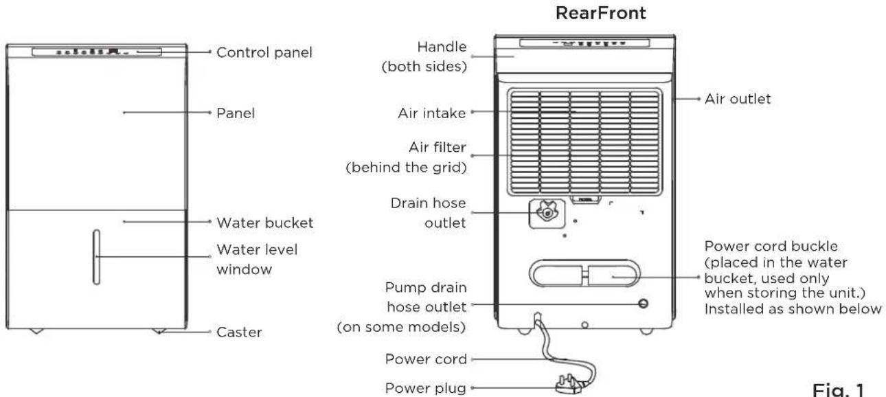
Fig. 1
NOTE
All the pictures in this manual are for illustrative purposes only. The dehumidifier you purchased may be slightly different, but its operations and functions are similar.
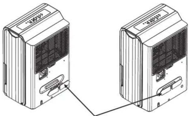
natural_image
Technical line drawing of two connected air purifiers with ventilation slots (no text or symbols)Insert the power cord buckle into the unit.
Fig. 2
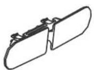
Accessories
Pump drain hose (1 pc) (only for units with the drain pump feature)
Power cord buckle (1 pc)
OPERATING INSTRUCTIONS
CAUTION
Clean your unit occasionally to keep it looking new. Be sure to unplug the unit before cleaning to prevent shock or fire hazards.
Key Pad Features
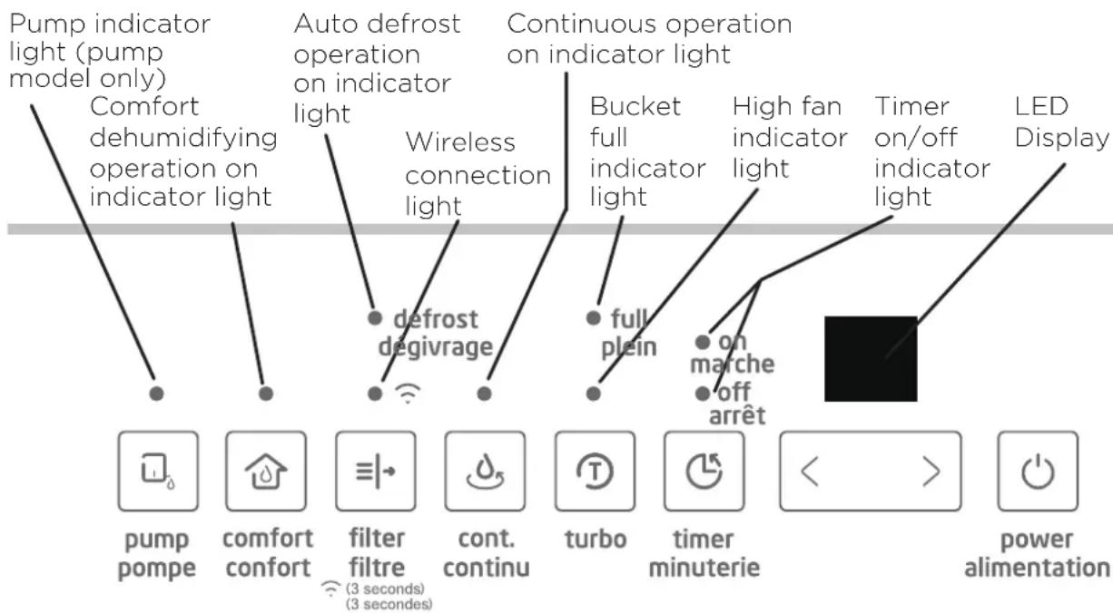
flowchart
graph TD
    A["Pump indicator light (pump model only)"] --> B["Comfort dehumidifying operation on indicator light"]
    C["Auto defrost operation on indicator light"] --> D["defrost dégivrage"]
    E["Continuous operation on indicator light"] --> F["full plein"]
    G["Bucket full indicator light"] --> H["on marche off arrêt"]
    I["High fan indicator light"] --> H
    J["Timer on/off indicator light"] --> H
    K["LED Display"] --> L["pump pompe"]
    K --> M["comfort confort"]
    K --> N["filter filtre"]
    K --> O["cont. continu"]
    K --> P["turbo"]
    K --> Q["timer minuterie"]
    K --> R["power alimentation"]
NOTE
The appearance of the control panel on your unit may vary slightly. Functions will be similar.
Control Pads
When you push the button to change operation modes, the unit will make a beep sound to indicate that it is changing modes.
(PUMP) Button (PUMP Models Only)
Press to activate the pump operation.
(COMFORT) Button
Press to activate the comfort dehumidifyin operation.
NOTE
Make sure the pump drain hose is installed into the unit and the drain hose is removed from the unit before the pump operation is activated. When the bucket is full, the pump starts to work. Refer to the next pages for removing the collected water. Do not use this operation when the outdoor temperature is equal to or less than 0^ C ( 32^ F).
NOTE
On this operation, the unit can not be set humidity level. For some models, under comfort dehumidifying operation, press Up/Down button will cancel this feature.
(FILTER) Button
This feature is a reminder to clean the Air Filter for more efficient operation. The LED (light) will flash after 250 hours of operation. To reset after cleaning the filter, press the Filter button and the light will go off. The 250 hour counter will reset.
(WIRELESS) Button
Press the filter button for 3 seconds when the unit is on or off to initiate the Wireless connection mode. The LED DISPLAY shows 'AP' to indicate you can set Wireless connection and the compressor is forced off. If connection (router) is successful within 8 minutes, the unit will exit Wireless connection mode automatically and the Wireless indicator illuminates and the compressor reverts previous state. If connection is failure within 8 minutes, the unit exits the Wireless connection mode automatically.
(CONTINUE) Button
Press to activate the continuous dehumidifying operation.
NOTE
When CONTINUOUS mode function is turned on, set humidity is automatic and cannot be changed manually.
(TURBO) Button
Control the Turbo speed. Press to select either Turbo or normal fan speed. Set the Turbo control to high for maximum moisture removal. When room humidity is at your preferred level, it is advised to turn off Turbo speed.
(TIMER) Button
Starts the Timer ON and Timer OFF function setting.
Up/Down Buttons ( ◀ / ▶
• Humidity Set Control Buttons
The humidity level can be set within a range of 35% RH (Relative Humidity) to 85% RH (Relative Humidity) in 5% increments.
For drier air, press the ◀ button and set to a lower value (%).
For damper air, press the ▶ button and set a higher value (%).
• TIMER Set Control Buttons
Use the ◀ and ▶ key buttons to set the Timer ON or Timer OFF from 0 to 24 hours.
(POWER) Button
Press to turn the dehumidifier on and off. LED Display
Shows the set % humidity level from 35% to 85% or auto start/stop time (0 \~ 24) while setting, then shows the actual (+/- 5% accuracy) room % humidity level in a range of 30% RH (Relative Humidity) to 90% RH (Relative Humidity).
Error Codes and Protection Code:
AS - Humidity sensor error - Unplug the unit and plug it back in. If error persists, contact Customer Service.
ES - Tube Temperature sensor of the evaporator error - Unplug the unit and plug it back in. If error persists, contact Customer Service.
P2 Bucket is full or bucket is not in right position - Empty the bucket and replace it in the right position. (only available for the unit with no pump feature.)
P2 - Bucket is full - Empty the bucket. (only available for the unit with pump feature.)
EC - Refrigerant leakage detection - Display area will show EC when the unit detects refrigerant leakage. If error persists, contact Customer Service.
Eb - Bucket is removed or not in right position - Replace the bucket in the right position. (only available for the unit with pump feature.)
Other Features
Bucket Full Light
Lights up when the bucket is ready to be emptied.
Auto Shut Off
The dehumidifier shuts off when the bucket is full, or when the bucket is removed or not replaced in the proper position. When the set point humidity level is reached, the unit will be shut off automatically. The fan motor will continue operating.
Auto Defrost
When frost builds up on the evaporator coils, the compressor will cycle off and Auto Defrost function will run automatically.
3 minute compressor operation delay protection
After the unit has stopped, it can not be restarted in the first 3 minutes to protect compressor operation. The unit will restart automatically after 3 minutes.
Auto-Restart
If the unit stops unexpectedly due to a power cut, it will restart with the previous function setting automatically when the power resumes.
Setting the Timer ON and Timer OFF
- When the unit is on, first press the Timer button, the Timer OFF indicator light illuminates. It indicates the Timer OFF program is initiated. Press it again the Timer ON indicator light illuminates. It indicates the Timer ON is initiated.
-
When the unit is off, first press the Timer button, the Timer ON indicator light illuminates. It indicates the Timer ON program is initiated. Press it again the Timer OFF indicator light illuminates. It indicates the Timer OFF is initiated.
-
Press or hold the ◀ and ▶ key buttons to change the Timer by 0.5 hour increments, up to 10 hours, then at 1 hour increments up to 24 hours. The control will count down the time remaining until start.
- The selected time will register in 5 seconds and the system will automatically revert back to display the previous humidity setting.
- When the Timer ON and Timer OFF times are set, within the same program sequence, indicator lights illuminate identifying both ON and OFF times are now programmed.
- Turning the unit ON or OFF at any time or adjusting the timer setting to 0.0 will cancel the Timer function.
- When LED display window displays the code of P2, the Auto Start/Stop function will also be cancelled.
NOTES
- When first using the dehumidifier, operate the unit continuously 24 hours. Make sure the plastic cap on the drain hose outlet install stightly properly so there are no leaks.
- This unit is designed to operate with a working environment between 5^ / 41^ and 32^ / 90^ .
- Make sure the water bucket is positioned correctly so that the unit can operate properly. When the water in the bucket reaches a certain level, please be careful while moving the unit to avoid it spill.
Removing Collected Water
There are three ways to remove collected water:
1. Use the bucket
- When the unit is off, if the bucket is full, the Full indicator light will light.
- When the unit is on, if the bucket is full, the compressor and the fan turn off, and the Full indicator light will light, the digital display shows P2.
- Slowly pull out the bucket. Grip the left and right handles securely, and carefully pull out straight so water does not spill. Do not put the bucket on the as because the bottom of the bucket is uneven. Otherwise water may be spilled.
• Empty the water and reposition the bucket. - The u nit will restart operation when the bucket is back in place.
NOTES
- When you remove the bucket, do not touch any parts inside the unit. Doing so may damage the product.
- Be sure to push the bucket gently all the way into the unit.
- If the pump hose falls off when you remove the bucket (see Fig. 7), you must reinstall the pump hose properly to the unit before replacing the bucket into the unit (see Fig. 8).
- When the unit is on, if the bucket is removed, the compressor and the fan turn off, then the unit will beep 8 times and the digital display shows Eb.
-
When the unit is off, if the bucket is removed, the unit will beep 8 times and the digital display shows Eb.
-
Pull out the bucket.
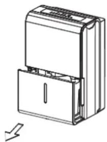
natural_image
Technical line drawing of a multi-chamber refrigerator with lid and door (no text or symbols)- Hold both sides of the bucket evenly, and pull it out from the unit.
Fig. 5
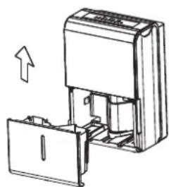
natural_image
Diagram of a device being inserted into a container, showing internal components and an upward arrow (no text or symbols)- Pour the water out.
Fig. 6
Pump hose drops
Fig. 7
natural_image
Technical line drawing of a mechanical device with internal components and a handle (no text or symbols)Reinstall pump
hose properly
Fig. 8
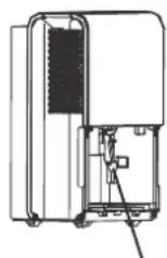
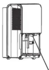
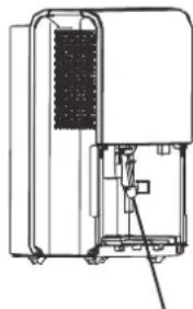
2. Continuous draining
- Water can be automatically emptied into a floor drain by attaching the unit with a water hose (Id ≥ ∅ 5/16", not included) with a female threaded end (ID: M = 1", not included).
- Remove the plastic cap from the back drain outlet of the unit and set aside, then insert the drain hose through the drain outlet of the unit and lead the drain hose to the floor drain or a suitable drainage facility. (See Fig. 9 and Fig. 10)
- When you remove the plastic cap, if there is some water in the back drain outlet of the unit you must dry it. Make sure the hose is secure so there are no leaks and the end of the hose is level or sloping downwards to let the water flow.
- Direct the hose toward the drain, making sure that there are no kinks that will stop the water flowing.
- Select the desired humidity setting and fan speed on the unit for continuous draining to start.
NOTE
When the continuous draining feature is not being used, remove the drain hose from the outlet, and dry the water in the drain hose outlet.
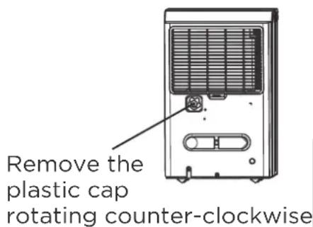
Fig. 9
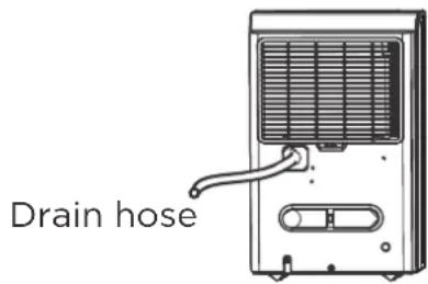
Fig. 10
Removing the Collected Water (cont.)
3. Pump draining (Pump models only)
Water can be automatically emptied into a floor drain or a suitable drainage facility by attaching the pump drain out with a pump drain hose ( od = 1/4", supplied).
- Remove the drain hose from the unit and install the plastic cap to the drain hose outlet of the unit by clockwise rotation. (See Fig. 11)
- Insert the pump drain hose into the pump drain hose outlet for at least 15 mm (See Fig. 11), then lead the water hose to the floor drain or a suitable drainage facility.
- Press the pump pad on the unit to activate the pump operation. When the bucket is full the pump starts to work.
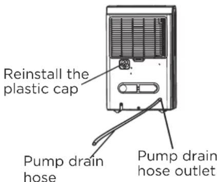
Fig. 11
NOTE
The pump may generate a loud noise for the first 3\~5 minutes of operation.
• Make sure the hose is secure so there are no leaks.
- Direct the hose toward the drain, making sure that there are no kinks that will stop the water flowing.
- Place the end of the hose into the drain.
- Select the desired humidity setting and fan speed on the unit for pump draining to start.
NOTE
The pump operation light blinks when a failure occurs. Please turn off the unit and disconnect the power cord. Check the following items:
- Cleaning the pump filter:
- Remove the bucket from the unit, take down the pump and clean the pump filter (See Fig. 12).
- Check if the drain hose is clean and free of debris.
• Empty the water from the bucket. - Check the hose connection and the bucket for proper fitment. If the error persists, contact Customer Service.
natural_image
Technical line drawing of an industrial machine with internal components and a tool (no text or symbols)Filter of the pump
Fig. 12
NOTE
Do not use this operation when the outdoor temperature is equal to or less than 0^ C ( 32^ F), otherwise water may freeze ice causing the water hose to be blocked and the unit to stop operating.
Make sure to empty the bucket at least once a week a week when using the pump draining feature. When the pump draining feature is not being used, remove the pump drain hose from the outlet.
INSTALLATION INSTRUCTIONS
Positioning the Unit
A dehumidifier operating in a basement will have little or no effect in drying an adjacent enclosed storage area, such as a closet, unless there is adequate circulation of air in and out of the area. (See Fig. 13)
- Do not use outdoors.
- This dehumidifier is intended for indoor residential applications only. This dehumidifier should not be used for commercial or industrial applications.
- Place the dehumidifier on a smooth, level floor strong enough to support the unit with a full bucket of water.
- Allow at least 8" of air space on all sides of the unit for air circulation (at least 16" for air outlet).
- Place the unit in an area where the temperature will not fall below 41°F (5°C). The coils can become covered with frost at at lower temperatures, which may reduce performance.
- Place the unit away from any clothes dryer, heater or radiator.
- Close all doors, windows and other outside openings to the room.
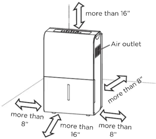
Fig. 13
CARE AND CLEANING
Turn the dehumidifier off and disconnect the plug from the power source before cleaning.
1. Clean the grid and Case
- Use water and a mild detergent. Do not use bleach or abrasives.
- Do not splash water directly onto the unit. Doing so may cause an electrical shock, cause the insulation to deteriorate, or cause the unit to rust.
- The air intake and outlet may get dirty during operation, use a vacuum cleaner or brush to clean.
2. Clean the bucket
Every few weeks, clean the bucket thoroughly to prevent growth of mold, mildew and bacteria. Partially fill the bucket with clean water and mild detergent. Swish it around in the bucket, empty and rinse.
NOTE
Do not use a dishwasher to clean the bucket.
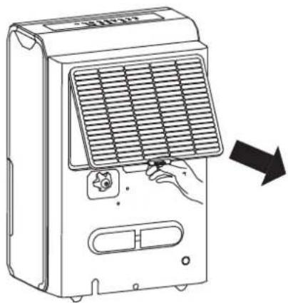
3. Clean the air filter
• To remove the filter, pull filter outwards (See Fig. 14).
- Wash the filter with clean water then dry.
- Re-install the filter, replace bucket.

CAUTION
DO NOT operate the dehumidifier without a filter to avoid loss of performance and damage to the unit.
4. When not using the unit for long time periods
- Before storing the unit, let it rest for one full day so that the system can dry out naturally.
- Clean the unit, water bucket and air filter.
- Wrap the cord with the power cord buckle.
• Cover the unit with a plastic bag. - Store the unit upright in a dry, well-ventilated area.
natural_image
Illustration of a portable air conditioner unit with a hand inserting a plug into the grille (no text or symbols)Fig. 14
TROUBLESHOOTING TIPS
Before calling for service, review this list. It may save you time and money. This list includes common occurrences that are not the result of defective workmanship or materials in this appliance.
Problem Solution
| Unit does not start | Make sure the dehumidifiers plug is connected firmly into the wall outlet. |
| Check the house fuse/circuit breaker box. | |
| Dehumidifier has reached its preset level or bucket is full. | |
| Water bucket is not in the proper position. | |
| Dehumidifier does not dry the air as it should | Not enough time to remove the moisture. |
| Make sure there are no curtains, blinds or furniture blocking the front or back of the dehumidifier. | |
| The humidity control may not be set low enough. | |
| Check that all doors, windows and other openings are securely closed. | |
| Room temperature is too low, below 5°C (41°F). | |
| There is a water vapor source in the room. | |
| The unit makes a loud noise when operating | Air filter may be dirty. Clean filter. Refer to Care and Cleaning section. |
| The unit is tilted instead of upright as it should be. | |
| The floor surface isnot level. | |
| Frost appears on the coils | This is normal. The dehumidifier has Auto defrost feature. |
| Water on floor | Hose to connector or hose connection may be loose. |
| Intended to use the bucket to collect water, but the back drain plug is removed. | |
| ES, AS, P2, EC, Eb and E3 appear in the display | These are error codes and protection code. Check Operating Instructions. |
| The pump operation on light blinks at 1 Hz | Clean the pump filter. |
| Check the pump hose is not blocked or leaking. | |
| Empty the water bucket. |
APP INSTRUCTIONS
1 Specification
Unit Model: MAD22C1AWS / MAD35C1AWS / MAD50C1AWS / MAD50P1AWS
Wireless Module Model: US-SK105
Antenna Type: Printed PCB Antenna
Frequency Band: 2400 - 2483.5MHz
Operation Temperature: 0° - 45°C / 32° - 113°F
Operation Humidity: 10% - 85%
Power Input: DC 5V / 500mA
Maximum TX Power: < 20dBm
2 Precautions
- App Compatibility:
- The app is available for both iOS and Android, however older versions may no longer be compatible. Please keep the app updated with the latest version. Midea makes no guarantee of compatibility and is not responsible for issues arising as a consequence thereof.
- The app is subject to updates without prior notice for product function improvement.
- Wireless Security:
- The Smart Kit supports the following security protocols: WPA-PSK / WPA2-PSK / WPA3-SAE
- It may be used with or without encryption although encryption is strongly recommended.
- Connectivity:
- Network issues may occasionally cause timeouts. The unit display and the app may become unsynchronized but this will resolve itself when the network is restored.
- Should the network remain unavailable, it might be necessary to run the configuration process again.
- Change in the wireless network will require reconfiguration of the device.
- Configuration:
- The actual network configuration process may vary slightly from the manual.
- Please check the service website for more information.
3 Using the SmartHome App

Ensure that your mobile phone is connected to the wireless network. Bluetooth must be turned on. The device must also be powered up.

Step 1: Download the SmartHome app
Scan the QR code below to download the SmartHome app from app store or search for it directly on the Google Play Store or Apple's App Store.


Step 2: Log in
Open the SmartHome app. Log in directly if you have an existing SmartHome account or create a new account.
Alternatively, you can also use a 3rd party login platform.


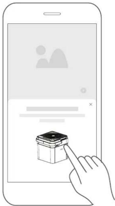
Step 3: Connecting the device
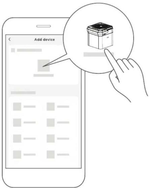
1) When you log in, you may see the message "Smart devices discovered nearby". Tap to add your device.
natural_image
Illustration of a hand interacting with a smartphone displaying a small icon (no text or symbols present)2) If no such message appears, proceed as follows:
Tap on "+" and select your device in the list of nearby available devices.
If your device is not listed, please add your device manually, first selecting the device category e.g. dehumidifier.
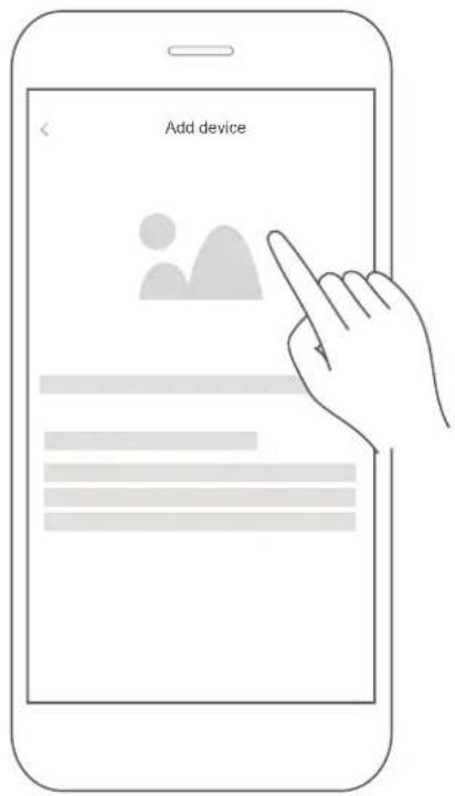
3) Follow the steps in the app to connect your device to the wireless network. If your device fails to connect, follow the additional instructions in the app.
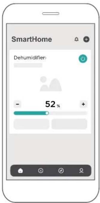
Step 4: Controlling the device
After pairing successfully, a card will be created for the device in the SmartHome app. Shortcuts for basic functions will appear on the card such as changing the humidity or switching the device on or off.
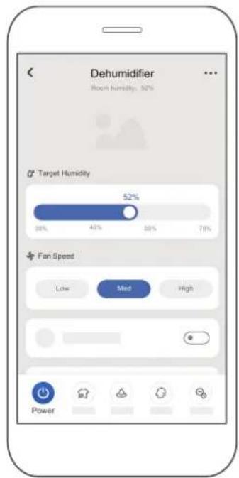
Tapping on the card, will reveal additional features and settings. The actual UI design may look different from examples due to app updates.

4 Compliance
We, hereby declare that this AC is in compliance with the relevant provisions of RE Directive 2014/53/EU. A copy of the full DoC is attached (Europen Union products only).
Wireless module models:
US-SK105:
FCC ID: 2ADQOMDNA21
IC: 12575A-MDNA21
This device complies with Part 15 of the FCC Rules and it contains licence exempt transmitter(s) / receiver(s) that comply with Innovation, Science and Economic Development Canada's licence-exempt RSS(s).
Operation is subject to the following two conditions:
(1) This device may not cause harmful interference;
(2) This device must accept any interference, including interference that may cause undesired operation of the device.
Only operate the device in accordance with the instructions supplied.
Changes or modifications to this unit not expressly approved by the party responsible for compliance could void the user's authority to operate the equipment.
This device complies with FCC radiation exposure limits set forth for an uncontrolled environment. In order to avoid the possibility of exceeding the FCC radio frequency exposure limits, human proximity to the antenna shall not be less than 20cm (8 inches) during normal operation.
In Canada:
CAN ICES-3(B)/NMB-3(B)
This equipment has been tested and found to comply with the limits for a Class B digital device, pursuant to part 15 of the FCC Rules. These limits are designed to provide reasonable protection against harmful interference in a residential installation. This equipment generates, uses and can radiate radio frequency energy and, if not installed and used in accordance with the instructions, may cause harmful interference to radio communications. However, there is no guarantee that interference will not occur in a particular installation. If this equipment does cause harmful interference to radio or television reception, which can be determined by turning the equipment off and on, the user is encouraged to try to correct the interference by one or more of the following measures:
- Reorient or relocate the receiving antenna.
- Connect the equipment into an outlet on a circuit different from that to which the receiver is connected.
- Consult the dealer or an experienced radio/TV technician for help.
Manufacturer:
GD Midea Air-Conditioning Equipment Co., Ltd.
Lingang Road Beijiao Shunde Foshan
Guangdong People's Republic of China 528311
Company will not be liable for any issues and problems caused by Internet, Wireless Router and Smart Devices. Please contact the original provider to get further help.
WARRANTY
Dehumidifier Limited Warranty
Your product is protected by this Limited Warranty:
Warranty service must be obtained from Midea Consumer Services or an authorized Midea servicer.
Warranty
• One year limited warranty from original purchase date.
Midea, through its authorized servicers will:
• Pay all costs for repairing or replacing parts of this appliance which prove to be defective in materials or workmanship.
Consumer will be responsible for:
• Diagnostics, removal, transportation and reinstallation cost required because of service.
• Costs of service calls that are a result of items listed under NORMAL RESPONSABILITIES OF THE CONSUMER**
Midea replacement parts shall be used and will be warranted only for the original warranty.
NORMAL RESPONSABILITIES OF THE CONSUMER\*\*
This warranty applies only to products in ordinary household use, and the consumer is responsible for the items listed below:
- Proper use of the appliance in accordance with instructions provided with the product.
- Routine maintenance and cleaning necessary to keep the good working condition.
- Proper installation by an authorized service professional in accordance with instructions provided with the appliance and in accordance with all local plumbing, electrical and/or gas codes.
- Proper connection to a grounded power supply of sufficient voltage, replacement of blown fuses, repair of loosen connections or defects in house wiring.
- Expenses for making the appliance accessible for servicing.
- Damages to finish after installation.
EXCLUSIONS
This warranty does not cover the following:
1) Failure caused by damage to the unit while in your possession (other than damage caused by defect or malfunction), by its improper installation, or by unreasonable use of the unit, including without limitation, failure to provide reasonable and necessary maintenance or to follow the written installation and Operating Instructions.
2) Damages caused by services performed by persons other than authorized Midea customer service; or external causes such as abuse, misuse, inadequate power supply or acts of God.
3) If the unit is put to commercial, business, rental, or other use or application other than for consumer use, we make no warranties, express or implied, including but not limited to, any implied warranty of merchantability or fitness for use or purpose.
4) Products without original serial numbers or products that have serial numbers which have been altered or cannot be readily determined.
NOTE: Some countries do not allow the exclusions or limitation of incidental or consequential damages. So this limitation or exclusion may not apply to you.
IF YOU NEED SERVICE
Keep your bill of sale, delivery slip, or some other appropriate payment Record.
The date on the bill establishes the warranty period, should service be required.
If service is performed, its your best interest to obtain and keep all receipts.
This written warranty gives you specific legal rights. You may also have other rights that vary from one country to another.
Service under this warranty must be obtained by following these steps, in order:
1) Contact Midea Consumer Services or an authorized Midea services at 1-888-365-2230.
2) If there is a question as to where to obtain service, contact our consumer relations Department.

make yourself at home

www.midea.com
© Midea 2024 all rights reserved
16120100A21515
20241017
natural_image
Line drawing of a refrigerant appliance with lid and side door (no text or symbols)DÉSHUMIDIFICATEUR MDP
GUIDE D'UTILISATION
MAD22C1AWS
MAD35C1AWS
MAD50C1AWS
MAD50P1AWS

- Servicing shall only be performed as recommended by the equipment manufacturer. Maintenance and repair requiring the assistance of other skilled personnel shall be carried out under the supervision of the person competent in the use of flammable refrigerants.
- DO NOT modify the length of the power cord or use an extension cord to power the unit.
- DO NOT share a single outlet with other electrical appliances. Improper power supply can cause fire or electric shock.
- Please follow the instructions carefully to handle, install, clean, or service the appliance to avoid any damage or hazard.
WARNING
natural_image
Technical line drawing of two electronic devices connected by a cable, showing internal components and wiring (no text or symbols)natural_image
Technical line drawing of a multi-chamber refrigerated unit with a door and ventilation slots (no text or symbols)natural_image
Diagram of a device with an open lid and internal compartments, showing an upward arrow (no text or symbols present)natural_image
Technical line drawing of a mechanical device with internal components and a handle (no text or symbols)natural_image
Technical line drawing of a mechanical device with internal components and a tool inserted (no text or symbols)Filtre de la pompe
Figure 12
DIRECTIVES D'INSTALLATION
natural_image
Line drawing of a portable air conditioner unit with a hand inserting a button to its side panel (no text or symbols)Figure 14
CONSEILS DE DÉPANNAGE
natural_image
Illustration of a hand interacting with a smartphone displaying a small icon (no text or symbols present)4 Conformité
GD Midea Air-Conditioning Equipment Co, Ltd.
Lingang Road Beijiao Shunde Foshan Guangdong
© Midea 2024 all rights reserved
16120100A21515
20241017

- USER MANUAL
- OWNER'S MANUAL
- Read This Manual
- CAUTION
- SAFETY PRECAUTIONS
- Explanation of Symbols
- WARNING
- Electronic Work
- WARNING:
- SAFETY MANUAL
- FOR R32 REFRIGERANT MODEL
- North America Products
- CAUTION:
- 9) Checks to electrical devices
- Sealed electrical components shall be replaced.
- Intrinsically safe components must be replaced.
- Cabling
- Detection of flammable refrigerants
- Removal and evacuation
- Charging procedures
- Decommissioning
- Labelling
- Recovery
- UNIT SPECIFICATIONS AND FEATURES
- Product overview
- NOTE
- Accessories
- OPERATING INSTRUCTIONS
- Control Pads
- (FILTER) Button
- (WIRELESS) Button
- (CONTINUE) Button
- (TURBO) Button
- (TIMER) Button
- Up/Down Buttons ( ◀ / ▶
- • TIMER Set Control Buttons
- (POWER) Button
- Error Codes and Protection Code:
- Other Features
- Bucket Full Light
- Auto Shut Off
- Auto Defrost
- minute compressor operation delay protection
- Auto-Restart
- Setting the Timer ON and Timer OFF
- NOTES
- Removing Collected Water
- Use the bucket
- Continuous draining
- Removing the Collected Water (cont.)
- Pump draining (Pump models only)
- INSTALLATION INSTRUCTIONS
- Positioning the Unit
- CARE AND CLEANING
- Clean the grid and Case
- Clean the bucket
- Clean the air filter
- When not using the unit for long time periods
- TROUBLESHOOTING TIPS
- APP INSTRUCTIONS
- Specification
- Precautions
- Using the SmartHome App
- Step 1: Download the SmartHome app
- Step 2: Log in
- Step 3: Connecting the device
- Step 4: Controlling the device
- Compliance
- Wireless module models:
- US-SK105:
- In Canada:
- Manufacturer:
- WARRANTY
- Dehumidifier Limited Warranty
- Midea, through its authorized servicers will:
- Consumer will be responsible for:
- NORMAL RESPONSABILITIES OF THE CONSUMER\*\*
- This warranty applies only to products in ordinary household use, and the consumer is responsible for the items listed below:
- EXCLUSIONS
- This warranty does not cover the following:
- IF YOU NEED SERVICE
- GUIDE D'UTILISATION
- DIRECTIVES D'INSTALLATION
- CONSEILS DE DÉPANNAGE
- Conformité
Brand : MIDEA
Model : MAD50P1AWS
Category : Dehumidifier