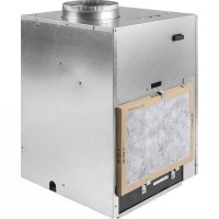
AZ91H09E5E - Air Conditioning GE - Free user manual and instructions
Find the device manual for free AZ91H09E5E GE in PDF.


| Product type | Reversible air conditioner (heat pump) |
| Brand | GE |
| Model | AZ91H09E5E |
| Cooling capacity | 9,000 BTU/h (estimated from model) |
| Power supply | 230 V / 208 V, 60 Hz, single-phase (265 V possible) |
| Electrical protection | Circuit breaker or time-delay fuse, 15 A to 30 A |
| Dimensions (W x D x H) | 23 1/8 x 23 1/8 x 30 5/8 in (587 x 587 x 778 mm) With duct: 32 3/4 in (832 mm) |
| Weight | Approximately 60 kg (estimated) |
| Refrigerant | R410A |
| Air filter | Disposable, dimensions 14 x 20 x 1 in for the unit Return grilles: 20 x 20 or 25 x 20 in |
| Filter replacement frequency | Every 30 days minimum |
| Electric heating power | 2.5 kW / 3.4 kW / 5.0 kW depending on configuration |
| Control type | Wall thermostat (not supplied) or integrated control panel |
| Functions | Cooling, heating (heat pump + electric), ventilation, freeze protection |
| Ventilation control | Sliding lever (open/closed) on the front panel |
| Condensate drainage | 3/4 in FPT connection, 3 locations (left, right, rear) |
| Air duct | 10 in collar on top |
| Maximum external static pressure | 0.30 in w.g. |
| Indoor airflow | 430-490 cfm (depending on speed and ESP) |
| Compatible wall thermostat | RAK164P2/D2 (electric resistance); RAK148P2/D2 (heat pump) |
| Warranty | 1 year parts and labor, 5 years sealed refrigeration system, 5 years selected motors and components |
Frequently Asked Questions - AZ91H09E5E GE
User questions about AZ91H09E5E GE
0 question about this device. Answer the ones you know or ask your own.
Ask a new question about this device
Download the instructions for your Air Conditioning in PDF format for free! Find your manual AZ91H09E5E - GE and take your electronic device back in hand. On this page are published all the documents necessary for the use of your device. AZ91H09E5E by GE.
USER MANUAL AZ91H09E5E GE
SAFETY INFORMATION 3
USING THE ZONELINE
Power Disconnect 4
Ventilation Control 4
Room Freeze Protection 4
About your Heat Pump 4
CARE AND CLEANING
Air Filters 5
Drain 5
Indoor/Outdoor Coils 6
Base Pan 6
INSTALLATION INSTRUCTIONS
Preparation 7,8
Ductwork 8
Accessories 9
Return Air Grille Options. 10
Utility Closet Connection Locations 10
Typical Closet and Dimensions 11
Installation Sequence 12
Plenum Installation 12
Grille Installation 12
Build Base Platform 12
Drain connection 13
Connect the Top Duct 14
Thermostat 15, 16
Electrical Connection 17, 18
Installation Checklist 18
Connect Power 18
TROUBLESHOOTING TIPS
Normal Operating Sounds 19
Troubleshooting Tips 20
Error Codes 21
CONSUMER SUPPORT
Product Registration 23, 24
Limited Warranty 25
Consumer Support 26
Write the model and serial numbers here:
Model #
Serial #
You can find them on a label on the top panel.
OWNER'S MANUAL
Heat Pump Models Small Chassis
AZ91H09D*E
AZ91H09E*E
AZ91H12D*E
AZ91H12E*E
ESPNOL
For a Spanish version of this manual, visit our Website at www.zoneline.com.
For a French version of this manual, visit our Website at www.zoneline.com.
THANK YOU FOR MAKING GE APPLIANCES A PART OF YOUR HOME.
Whether you grew up with GE Appliances, or this is your first, we're happy to have you in the family.
We take pride in the craftsmanship, innovation and design that goes into every GE Appliances product, and we think you will too. Among other things, registration of your appliance ensures that we can deliver important product information and warranty details when you need them.
Register your GE appliance now online. Helpful websites and phone numbers are available in the Consumer Support section of this Owner's Manual. You may also mail in the pre-printed registration card included in the back of this manual.

GE APPLIANCES
IMPORTANT SAFETY INFORMATION READ ALL INSTRUCTIONS BEFORE USING THE APPLIANCE

WARNING
For your safety, the information in this manual must be followed to minimize the risk of fire, explosion, electric shock, property damage, personal injury, or loss of life.
SAFETY PRECAUTIONS
This Zoneline must be properly installed in accordance with the Installation Instructions before it is used. See the Installation Instructions in the back of this manual.
- Disconnect the Zoneline at the fuse box or circuit breaker before making any repairs.
NOTE: We strongly recommend that any servicing be performed by a qualified individual.
All air conditioners contain refrigerants, which under federal law must be removed prior to product disposal. If you are getting rid of an old product with refrigerants, check with the company handling disposal about what to do.
These R410A air conditioning systems require contractors and technicians to use tools, equipment and safety standards approved for use with this refrigerant. DO NOT use equipment certified for R22 refrigerant only.
Features
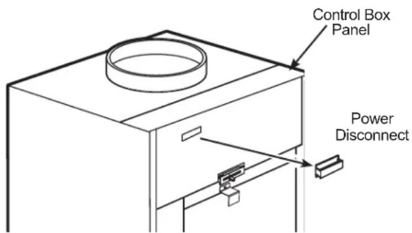
Power Disconnect
The power disconnect is located on the front of the Zoneline.
NOTE: The power disconnect does not remove power from the terminal block located under the control box panel.

WARNING
Electric Shock Hazard
Before servicing, disconnect power to the Zoneline at the fuse box or circuit breaker and pull out electrical disconnect on front of the chassis.
Failure to do so can result in personal injury and/or death.
Ventilation Control
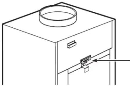
The ventilation control lever is located on the front of the Zoneline unit.
When the lever is in the CLOSE position, only the air inside the room is circulated and filtered.
When the lever is in the OPEN position, some outdoor air will be drawn into the room. This will reduce the heating or cooling efficiency.
To close the vent, move the slide lever to the right.
To open the vent, move the slide lever to the left.
Energy Tip: Keep the vent control in the CLOSE position. The room air will be filtered and circulated.
NOTE: Ventilation openings are not intended to be the source of make-up air for building ventilation systems due to the additional heating and cooling loads generated.
Ventilation Control Slide Lever
Room Freeze Protection
This feature will monitor the indoor room conditions and in the event that the room falls below 40^ the unit will cycle on high fan with the electric heater. This occurs regardless of mode as long as power is applied to the unit.
About Your Heat Pump (on some models)
Heat pumps can reduce operating costs by exchanging heat from the outside air—even when the outside temperature is below freezing—and releasing that heat indoors.
To get the best economic benefit from your heat pump, don't change the room thermostat setting very often. Raising the heat setting 2-3 degrees will cause the Zoneline to use its electric heating elements in order to reach the new temperature setting quickly.
There is a three minute minimum compressor run time at any setting to prevent short cycling.
The indoor fan motor starts before the compressor and stops after the compressor cycles off.
The electric heating elements use much more electricity than heat pumps and cost more to operate.
Care and Cleaning
Air Filters
NOTICE: Do not operate the Zoneline without the filter in place. If a filter becomes torn or damaged, it should be replaced immediately.
Operating without the filter in place or with a damaged filter will allow dirt and dust to reach the indoor coil and reduce the cooling/heating, performance, airflow and efficiency of the unit.
The most important thing you can do to maintain the Zoneline is to change the filter at least every 30 days. Dirty filters reduce cooling, heating performance and air flow.
Changing the filter will: Decrease cost of operation, save energy, prevent clogged heat exchanger coils and reduce the risk of premature component failure.
Replacement filters should be purchased from your local retailer where air conditioner and furnace accessories are sold.
Filter size for front of unit is 14^ × 20^ × 1 .
Filter sizes for RAVRG1 and RAVRG2 are 20^ × 20^
Filter sizes for RAVRG3 is 25^ × 20^ .
NOTE: Use only one filter in the installation.
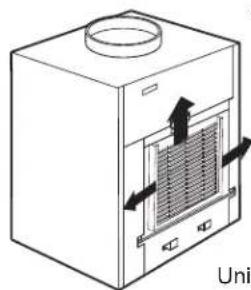
To replace the filter (chassis mounted return air filter):
- Slide the filter to the right or left to clear the filter holders or rotate upper filter holder to clear top of the filter.
- Remove the filter.
- Install new disposable filter.
To maintain optimum performance, change the filter at least every 30 days.
To remove and replace the filter:
Remove filter
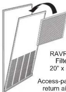
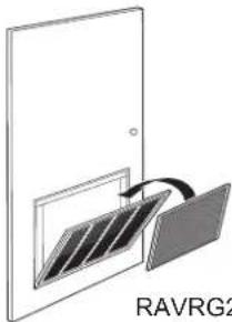
RAVRG1 Filter 20^ × 20^
Access-panel with return air grille
RAVRG2 Filter 20^ × 20^
Return air grille
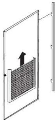
RAVRG3 Filter 25^ × 20^
Access-panel with return air grille Hinge on left Side of door
Drain
Clean the drain system regularly to prevent clogging.
The condensate drain must be routed to a suitable drainage area. Check the unit condensate drain periodically. Keep it free of anything that may block or impeded the flow of condensate water. If there is any accumulation of foreign matter in the drain pipe, it should be removed and cleaned. The entire drain line must be protected from freezing.
Care and Cleaning
Indoor/Outdoor Coils
The Indoor/Outdoor coils on the Zoneline should be cleaned and checked regularly.
NOTE: When cleaning the coils do not use acid based coil cleaners. Care must be taken to avoid bending the aluminum fins on the coils.
Indoor-Air Coil
Minor amounts of lint and dirt may pass through the filter and collect on the indoor-air coil. These minor accumulations can be carefully vacuumed away with a brush attachment on a vacuum cleaner or professionally steam cleaned away.
Outdoor-Air Coil
The unit's outdoor-air intake and outdoor-air exhaust paths must remain clear. Check the outdoor-air exhaust frequently. Keep it free of all debris, snow, or ice. The outdoor-air intake should also be kept free of obstructions. Blocking the outdoor-air exhaust or outdoor-air intake opening will reduce the efficiency of your unit and could cause premature compressor failure.
Inspection and cleaning of the outdoor-air coils may require the unit to be removed from the closet. See servicing section of this manual for instructions on how to remove the unit.
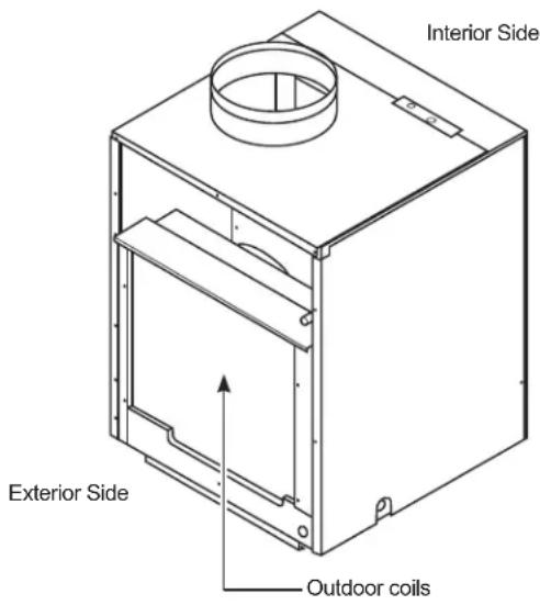
Have the coils cleaned regularly.
Base Pan
In some installations, dirt or other debris may be blown into the unit from the outside and settle in the base pan (the bottom of the unit).
In some areas of the United States, a "gel-like" substance may be present in the base pan.
Check it periodically and clean, if necessary.
Questions? Call 844-GE4-PTAC (or 844-434-7822) or Visit our Website at: GEAppliances.com
BEFORE YOU BEGIN
Read these instructions completely and carefully.
- IMPORTANT - Save these instructions for local inspector's use.
- IMPORTANT - Observe all governing codes and ordinances.
Note to Installer - Be sure to leave these instructions with the owner.
Note to Owner - Keep these instructions for future reference. - Proper installation is the responsibility of the installer.
Product failure due to improper installation is not covered under the Warranty. - You must use all supplied parts and use proper installation procedures as described in these instructions when installing this air conditioner.
ELECTRICAL REQUIREMENTS
| Wire Size Use | ONLY wire size recommended for single outlet branch circuit |
| Fuse/Circuit Breaker | User ONLY type and size fuse or HACR circuit breaker indicted on units rating plate. Proper over current protection to the units is the responsibility of the owner. |
| Grounding Unit | MUST be grounded from branch circuit to unit, or through separate ground wire provided on permanently connected units. Be sure that branch circuit is grounded. |
| Wire Sizing U | secommended wire size given in tables and install a single branch circuit. All wiring must comply with local and national codes. NOTE: Use copper conductors only. |
NOTE: All field wiring must comply with NEC and local codes. It is the responsibility of the installer to insure that the electrical codes are met.
IMPORTANT ELECTRICAL SAFETY-READ CAREFULLY

WARNING
- All electrical connections and wiring MUST be installed by a qualified electrician.
- Follow the National Electrical Code (NEC) and local codes and ordinances.
- For personal safety, this Zoneline must be properly grounded.
- Protective devices (fuses or circuit breakers) acceptable for Zoneline installations are specified on the nameplate of each unit.
- Do not use an extension cord with this unit.
- Aluminum building wiring may present special problems—consult a qualified electrician.
- When the unit is not running there is still voltage to the electrical controls.
-
Disconnect the power to the unit before servicing by removing the branch circuit fuses or turning the circuit breakers off at the panel.
-
Use ONLY the wiring size recommended for single outlet branch circuit.
- Proper current protection is the responsibility of the owner.
| Recommended branch circuit wire sizes* | |
| Nameplate maximum circuit breaker size | AWG Wire size** |
| 15A | 14 |
| 20A | 12 |
| 30A | 10 |
| AWG – American Wire Gauge * Single circuit breaker from main box ** Based on 100' or less of copper wire, single insulated conductor at 60°C. Wire sizes are per NEC. | |
NOTE: Use copper conductors only.
Indoor Air Flow Data
=Indoor air flow may be determined by measuring the external static pressure (ESP) of the duct system using an inclined manometer or magnehelic gauge, then consulting chart "A" to determine actual air flow. Use the air flow correction multipliers contained in chart "B" to determine accurate air flow under the listed conditions. Under no circumstances should the SPVU equipment be operated at an external static pressure in excess of .30 W.C. Operation of the SPVU under these conditions will result in inadequate air flow leading to poor performance and/ or premature component failure.
Chart A - CFM - Determining the Indoor CFM
| Models | ||
| AZ91H09 / AZ91H12 | ||
| Fan Speed | Low High | |
| ESP(")=SCFM | ||
| .10"=430=490 | ||
| .15"=410=470 | ||
| .20"=360=440 | ||
| .25"=310=400 | ||
| .30"=260=350 | ||
ESP = external static pressure in inches water column
Rated CFM at Low Speed:
$$ A Z 9 1 H 0 9 = 3 5 0 $$
$$ A Z 9 1 H 1 2 = 4 1 0 $$
For single speed thermostats connect to the GL terminal for Low Speed or GH terminal for High Speed. Two speed control thermostats will use both terminals.
Chart B - Correction Multipliers Correct CFM (if needed)
| Correction Multipliers for: | |
| 230V/265V=1.00 | |
| 208V=0.97 | |
| Heating 1.00 | |
| Cooling 0.95 | |
Your airflow should be balanced based on many factors, such as available ESP, room CFM, and ductwork. Consult an HVAC engineer for proper applications. External static pressure (ESP) can be measured with a manometer or pitot tube. Once this ESP is established, you can calculate the CFM using the above chart.
Higher CFMs tend to increase SENSIBLE capacity, enhance room circulation and increase duct noise, while lower CFMs tend to increase LATENT capacity and reduce noise.
Ductwork
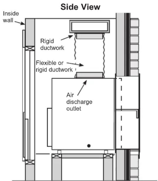
=The supply duct system should be designed via a recognized method such as the equal friction method, or velocity reduction method, using the appropriate duct calculator(s) for the type(s) of duct (i.e. metal duct, duct board, or flex duct) being used in the system. The duct system should be designed for a maximum friction rate of .30" water column taking into consideration all fittings, registers and/or diffusers. DO NOT operate unit without a supply duct attached.
=The return air to SPVU series units MUST NOT be ducted, and all units MUST have a free return air configuration to perform properly.
The total flow rate (CFM) and external static pressure (ESP) available can be estimated from the chartsto the left. Use these charts to select your fan speed setting.
=The collar on top of the unit accepts standard 10 " duct. Pull all duct tight. Extra duct slack can greatly increase static pressure.
NOTICE: Flex duct can collapse and cause airflow restrictions. Do not use flex duct for 90^ bends or unsupported runs of 5 ft. or more.
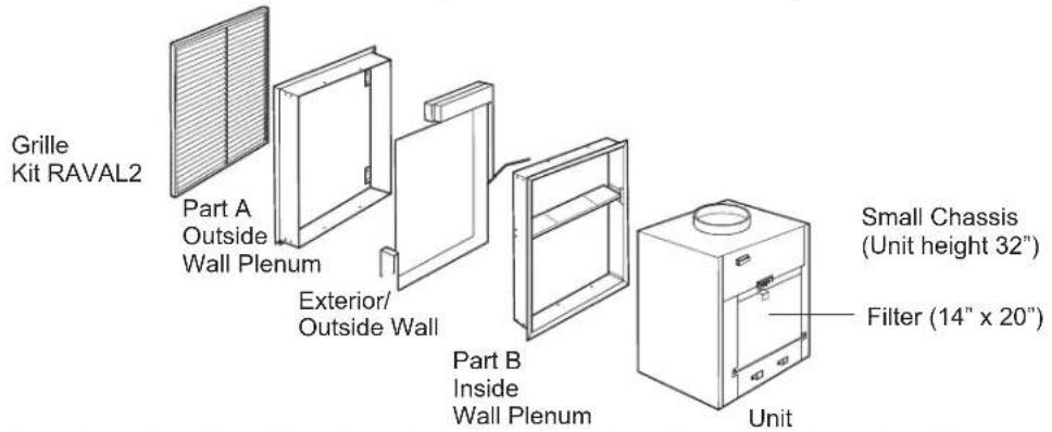
ZONELINE COMPONENTS (Small Chassis)
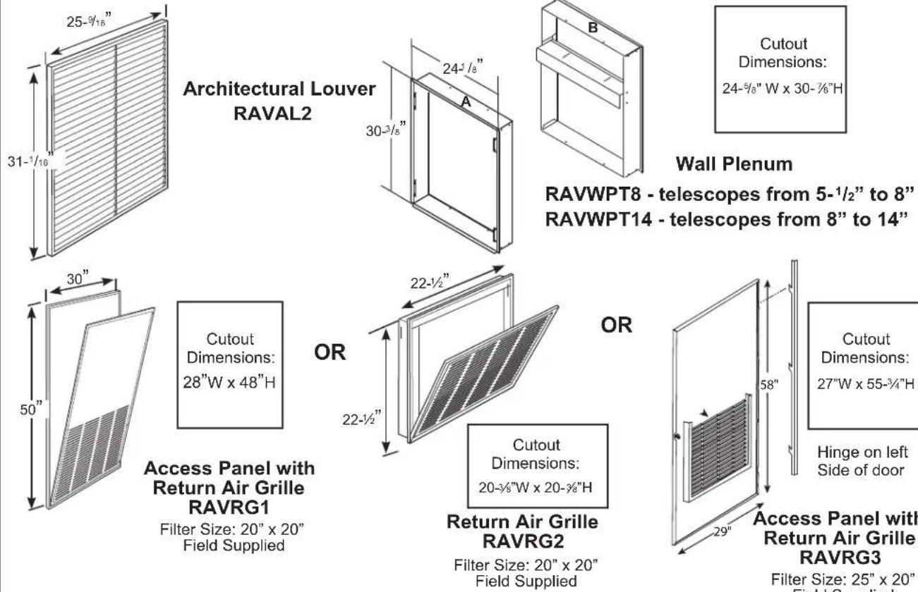
REQUIRED ACCESSORIES for NEW Installation*
- For conversions from AZ75/AZ85 series to AZ90/AZ91 series vertical air conditioners RAVTRANS Kit is required.
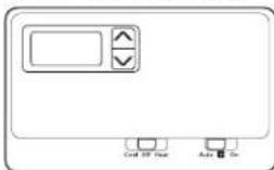
Wall Thermostat
| Model Type Electronic | Thermostat | Kit Number |
| Electric Resistance Models 5-wire | RAK164P2 and RAK164D2 | |
| Electric Resistance Models 6-wire | RAK164F2 | |
| Heat Pump Models 6-wire RAK | 148P2 and RAK148D2 | |
| Heat Pump Models 7-wire RAK | 148F2 |
RETURN AIR GRILLE INSTALLATION OPTIONS
The room return air grille may be installed toward the front or either side of the unit. Improper return air arrangements will cause performance problems.
There are four indoor return air grille installation options. Choose the option that best suits your installation requirements. Follow the Installation Instructions provided with the return air grille accessory for installation details.
NOTE: Use only one filter in the installation. The filter may be installed on the unit or in the access panel/door.
UTILITY Closet CONNECTION LOCATIONS
IMPORTANT: Plan and locate plenum, electrical connection, drains and thermostat carefully to avoid interference. Hard-to-reach locations will make installation and service difficult!
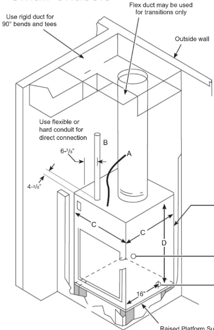
Small Chassis
Reference Dimensions
A Thermostat cable
B Incoming Power Conduit
C Unit width and depth: 23 - 1%
D Unit height: 30^5/8 (32-3/4" with duct)
E Condensate drains: 3 / 4 connector Choose one of THREE Primary Drain locations (select one location and plug the other two):
- 1 - Right Side
-1-LeftSide
- 1 - Back (Plenum) Side
- Secondary drain water flows into plenum from the back of the unit.
Unit slides into wall plenum approximately 2".
Primary Drains
- A drain connection is located on the back of the unit approximately 2^ from the left side.
- A drain connection is located on the right and left side of the unit approximately 16" from the front of the unit.
Raised Platform Surface recommended 8^ minimum height.
Installation Overview
SMALL CHASSIS TYPICAL UTILITY COLOSET AND DIMENSIONS
(FOR REFERENCE ONLY)
UNIT INSTALLED THROUGH FRONT OF PLENUM
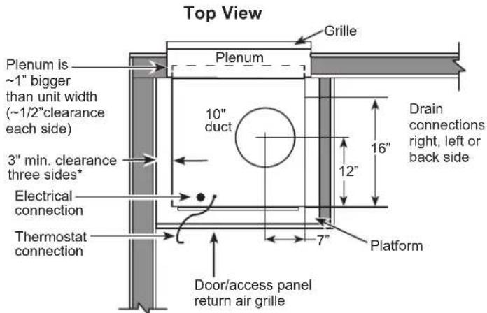
* It is recommended to leave additional space around the unit to ease installation and access for service.
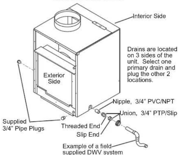
Drain Locations
Side View
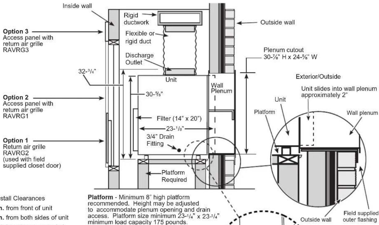
Front Install Clearances
- 3" min. from front of unit
- 3" min. from both sides of unit Side Installs not recommended
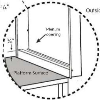
Plenum opening must be 3 / 4 above platform surface for small chassis installation.
Available Accessories
Architectural Louver - RAVAL2
Wall Plenum - RAVWPT8 - telescopes from 5- 1 / 2 to 8
Wall Plenum - RAVWPT14 - telescopes from 8" to 14"
- Access Panel with Return Air Grille - RAVRG1
- Return Air Grille - RAVRG2
- Access Panel with Return Air Grille - RAVRG3
- Wall Thermostat (Digital and Programmable)
Installation Instructions
INSTALLATION SEQUENCE
- Plan for proper electrical supply, drains and ductwork locations.
- Install wall plenum.
- Install the grille.
- Build and install platform.
-
Place unit on the platform and slide the exterior side of the unit into the plenum until it is fully seated.
-
Make drain connections per instructions included in this manual.
- Connect unit to the ductwork.
- Connect the thermostat.
- Connect the electrical power.
- Install air return grille or access cover.
- Review the installation checklist.
- Check operation of the unit.
INSTALLATION INSTRUCTIONS
Install the Wall Plenum
Install the wall plenum. Refer to instructions included in the wall plenum kit RAVWP8 or RAVWPT14 for proper installation procedures.
Install the Grille
Install the grille. Refer to instructions included in the grille kit RAVAL2 for proper installation procedures.
Build and Install the Zoneline Base Platform
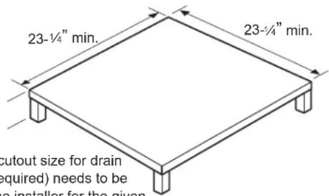
- Construct a 23 - 14^ min. x 23 - 14^ min. square platform with legs to raise the platform a minimum of 8^ . NOTE: The platform must have a load-bearing capacity of 175 lbs. minimum.
Recommended platform height: 8^ min for drain access. Platform surface should be 3 / 4 below wall plenum opening. See Plenum Installation Instructions for details
NOTE: Specific cutout size for drain connections (if required) needs to be determined by the installer for the given installation situation.
-
Drain connections can be made to the right, left or rear of the unit. The unit dimensions are 23^-1 / 8 x 23^-1 / 8 . If the platform is larger than the unit, drain holes may need to be cut through the platform. Drain cutouts/ connections need to be determined by the installer for the given installation situation.
-
Place the platform in the utility closet with the following clearance between it and the interior surface of the walls/door-panel:
-
3" min. from front of the unit - Unit to be installed through FRONT of case
-
3" min. from two sides of the unit
-
Align the platform with the opening of the wall plenum and secure to the floor using appropriate brackets and bolts.
Condensate Disposal System
The Condensate Disposal System increases energy efficiency utilizing a factory installed fan that slings the condensate onto the hot outdoor coil.
When high outdoor humidity prevents the slinger from disposing of all condensate, the excess condensate overflows into the condensate drain pan and out of the 3/4 internal drain connections.
NOTE: If the Condensate Disposal System fails to remove all of the condensate from the unit, any excess condensate will overflow from a spillway in the rear of the unit directly into the wall plenum, and drain outside the building. This is your indication that the chassis or drain requires servicing.
DRAIN CONNECTION AND LOCATION
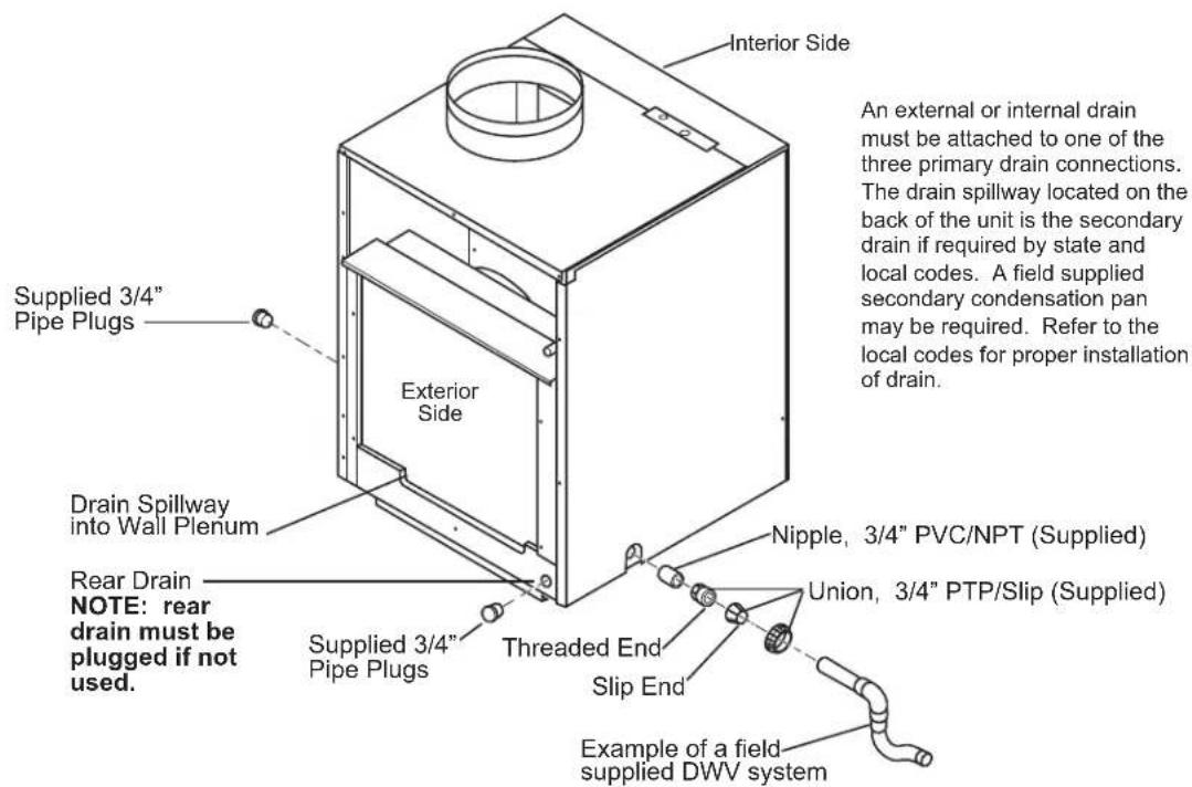
Making Drain Connections
NOTE: Prior to sliding the unit into the wall plenum determine where to make the drain connections. If the rear drain is not going to be used it must be plugged prior to sliding the unit into the wall plenum.
1 The unit base pan has three (3) previsions (left, right and rear) for connecting an external condensate drain.
2 The supplied drain kit must be connected to one of the three (left, right or rear) 3/4'' FPT connections on the unit base pan. Use of rear drain without connecting to DWV system (drain, waste, vent) may result in staining of the outside wall.
3 Insert the provided 3/4 nipple into the determined connection using field supplied Teflon tape or pipe joint compound.
4 With the threaded end of the supplied 3/4 union, connect to the nipple with Teflon tape or pipe joint compound.
5 The remaining two drain connections must be plugged using the two 3/4 pipe plugs (provided) and field supplied Teflon tape or pipe joint compound.
6 Hand-tighten all fittings to prevent damage to unit or fittings.
7 Place unit onto the platform and align the back of the unit with the wall plenum opening. Slide the unit into the plenum approximately 2^ (or until unit stops).
8 A field supplied drain system must now be installed to the slip end of the union. A trap is recommended and drain connection should be connected to building DWV system.
9 Pitch the drain line on a 1 / 4 downward slope for every foot (1^) of lateral horizontal run to the DWV.
10 Do not thread metal or copper pipe fittings directly into unit.
11 Check system for leaks.
12 Failure to follow these procedures may result in serious property damage.
13 A field supplied secondary condensate pan may be required. Check with local codes.
Connect the Top Duct
- Install the duct onto the air discharge outlet.
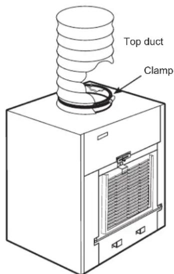
2. Use a field supplied clamp to secure the top duct to the air discharge outlet.
Remote Thermostat
AWARNING
Electric Shock Hazard
Before servicing, disconnect power to the Zoneline at the fuse box or circuit breaker and pull out electrical disconnect on front of the chassis.
Failure to do so can result in personal injury and/or death.
All SPVU units are factory configured to be controlled by using a single stage heat/cool remote wall mounting thermostat. The thermostat may be auto or manual changeover as long as the control configuration matches that of the SPVU unit.
NOTE: See the Remote Thermostat and Low Voltage Control Connections sections of this manual and the manual with the separate thermostat for proper connections and settings.

IMPORTANT:
The Zoneline thermostat connections provide 24V AC only.
If using a digital/electronic wall thermostat you must set it to the 24V AC setting. See the Installation Instructions for the wall thermostat.
NOTICE:
Damage to a wall thermostat or to the Zoneline electronics can result from improper connections. Exercise extra attention when connecting blue and black wires. No line voltage connections should be made to any circuit in the thermostat. Isolate all wires in building from line voltage.
REMOTE THERMOSTAT
AND LOW VOLTAGE CONTROL CONNECTIONS
To Connect the wall-mounted thermostat
Terminal connections are located under the control box panel.
- Pull the power disconnect located in the front of the chassis.
- Disconnect the power coming into the unit from the main breaker panel or the closet mounted disconnect.
- Remove the control box panel by removing the 4 front screws and 3 top screws that secure the panel.
- Run the thermostat wires through the small hole on the top of the box to reach the terminal connections on the right side of the control.
- Make the wire connections per the instructions that are included with the thermostat.
6 Once each wire is matched and connected, the unit is now ready for operation. - Reattach the control box panel.
Thermostat terminals requirements
For cooling with electric heat units: C, R, GL, Y, W. For heat pump units: C, R, GL, Y, W, B.
For two fan speeds, thermostat must have 2 fan speed selection.
Heat Pump Units During Heat Mode:
The B terminal must be continuous energized. The W terminal must have 24 VAC output to call for heat. The control board decides on whether to turn on the Heat Pump Heat (compressor) or Electric Heat. The Y terminal should not have 24 VAC output during the Electric Heat mode.

CAUTION
Improper CDC wiring may damage the Zoneline electronics or cause erratic Zoneline operation. No Common busing is permitted. A separate wire pair must be run from each separate controlling switch to each individual Zoneline.
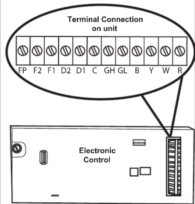
| Interface Definition | |
| Terminal Code | Wire Connection Function |
| FP Factory use | only. (Ensure there is not jumper at FP and F2) |
| F2 Used with F1 | to provide 24 VAC to external fan relay. (Ensure there is no jumper at FP and F2) |
| F1 Used with F2 | to provide 24 VAC to external fan relay |
| D2 Used with D1 | 1 for desk control on or off operation |
| D1 Used with D2 | 2 for desk control on or off operation |
| C Common Ground Terminal | |
| GH Call for High | Fan |
| GL Call for Low | Fan |
| B Call for Heat Pump | Pump Reversing Valve |
| Y Call for Compessor | |
| W Call for Heating | |
| R 24V Power from Electronic Control to Wall Thermostat | |
Installation Instructions
REMOTE THERMOSTAT AND LOW VOLTAGE CONTROL CONNECTIONS
Desk Control Terminals
The SPVU has built-in provisions for connection to an external switch to control power to the unit. The switch can be a central desk control system or even a normally open door switch.
For desk control operation, connect one side of the switch to the D1 terminal and the other to the D2 terminal. Whenever the switch closes, the unit operation will stop.
NOTE: The desk control system and switches must be field supplied.
Maximum Wire Length for Desk Control Switch
| Wire Size Maxim um Length | |
| #24 400 ft. | |
| #22 600 ft. | |
| #20 900 ft. | |
| #18 1500 ft. | |
| #16 2000 ft. | |
Auxiliary Fan Control
The Smart Center also has the ability to control a 24VAC relay to activate an auxiliary, or transfer, fan. The outputs are listed as F1 and F2 on the control board.
To connect the relay, simply wire one side of the relay to F1 and the other side to F2. Anytime that the fan runs, the terminals will send a 24VAC signal to the relay. The relay must be 24VAC, 100mA or less.
NOTE: The relay and auxiliary fans must be field supplied.
NOTE: It is the installer's responsibility to ensure that all control wiring connections are made in accordance with the installation instructions. Improper connection of the thermostat control wiring and/or tampering with the unit's internal wiring can void the equipment warranty and may result in property damage, personal injury or death.
Air Return Panel/Grille
Install the air return grille or access cover. Refer to instructions included with the kit chosen.
ELECTRICAL CONNECTIONS
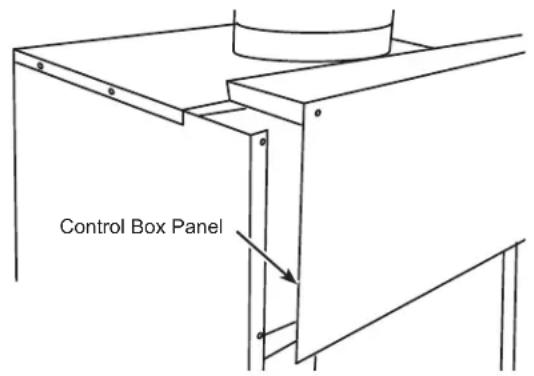
1. REMOVE CONTROL BOX PANEL

WARNING
Electric Shock Hazard
Before servicing, disconnect power to the Zoneline at the fuse box or circuit breaker and pull out electrical disconnect on front of the chassis.
Failure to do so can result in personal injury and/or death.
Remove the control box panel by taking out the front 4 screws and the 3 top screws.
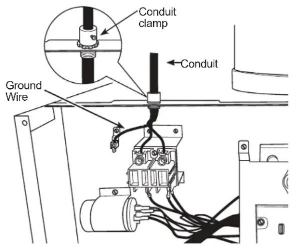
2. ATTACH CONDUIT
Use the round knockout hole at the top of the control box to install conduit coming from the branch circuit. Install and clamp the conduit through the conduit clamp and bring wire leads into the junction box. Leave 8" of wire free from the end of the conduit.
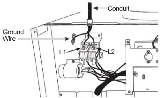
3. MAKE WIRE LEAD CONNECTIONS INSIDE THE CONTROL BOX

WARNING
RISK OF ELECTRIC SHOCK
Can cause injury or death. This appliance must be properly grounded.
Turn OFF electrical power before service or installation.
Pull the power disconnect located in the front of the chassis. Disconnect the power coming into the unit from the main breaker panel or the closet mounted disconnect.
NOTE:
- All electrical connections and wiring must be installed by a qualified electrician and conform to the National Electric Code (NEC) and all local codes which have jurisdiction.
- All chassis must be hard wired with properly sized breakers. Use HACR type breakers to avoid nuisance trips.
-
Unit must be properly grounded.
-
Make all wire connections by using appropriate UL-listed electrical connectors and techniques.
- Be sure that all wire leads are inside the control box and not pinched between the panel and the unit. The green insulated ground wire from the Zoneline MUST BE connected to the branch circuit ground wire.
- Replace the control box panel and secure to the unit by replacing the 7 screws removed earlier.
Installation Instructions
ELECTRICAL CONNECTIONS (continued)
DIRECT CONNECTION
| Heater Wattage @ 230/208 Volts | Circuit Protective Device |
| 2.50/2.05 KW | 15-Amp Time Delay-Fuse or Breaker |
| 3.40/2.78 KW | 20-Amp Time Delay-Fuse or Breaker |
| 5.00/4.09 KW | 30-Amp Time Delay-Fuse or Breaker |
| Heater Wattage @ 265 Volts | Circuit Protective Device |
| 2.50 KW | 15-Amp Time Delay-Fuse or Breaker |
| 3.40 KW | 20-Amp Time Delay-Fuse or Breaker |
| 5.00 KW | 30-Amp Time Delay-Fuse or Breaker |
- See NEC for application for 265 Volts.
FINAL INSTALLATION
FINAL INSTALLATION CHECKLIST
Ensure that all installation instructions concerning clearances around the unit have been adhered to.
Inspect and ensure that all components and accessories have been installed properly and that they have not been damaged during the installation process.
- Wall plenum flashing is installed, plenum level and called.
Unit is level, front to back and left to right.
Check to ensure that the unit air filter, indoor coil, and outdoor coil are free from any obstructions.
Check to make sure only one air filter is installed in the system.
Check the condensate water drain(s) to ensure that they are connected and adequate for the removal of condensate water and that they meet approval of the end user.
Ductwork is connected and secure to air discharge outlet.
Secure all access panels (i.e. front cover and/or control box).
Wall thermostat is wired correctly.
Unit is wired correctly.
Ensure that the circuit breaker(s) /fuse(s) and supply circuit wire size have been sized correctly.
Ensure the unit has correct line voltage to it, is on a single circuit and is properly grounded.
Ensure that the entire installation is in compliance with all applicable national and local codes and ordinances having jurisdiction.
CONNECT POWER
- If all the items on the checklist are correct, reinstall the power disconnect on the front of the unit.
- Turn the power on at the main service panel.
- Turn on and adjust the thermostat so the unit begins to run.
- Check for proper operation in each mode. Instruct the owner or operator regarding the unit's operation, and the recommended routine maintenance schedule.
NOTE: Maintaining a log for recording the dates of maintenance and/or service is recommended, and should be suggested to the owner or operator of the equipment.
SERVICING
WARNING
Risk of Electric Shock, can cause injury or death. Before servicing, switch power off at the service panel and lock the area to prevent power from being switched on accidentally. When the area cannot be locked, securely fasten a prominent warning device, such as a tag, to the service panel.
NOTE: We strongly recommend that any servicing be performed by a qualified individual.
To remove the unit from the closet.
- Switch the wall thermostat to off.
- Pull the Power Disconnect located in the front of the chassis.
- Turn off all power coming into the unit at the main breaker panel or the closet mounted disconnect.
- Disconnect the electrical connection at the unit.
- Disconnect the drain system.
- Disconnect the duct work.
- Slide the chassis out of the wall plenum.
- Lift the chassis out of the utility closet.
Normal Operating Sounds
| PING! POP! | You may hear a pinging noise caused by water being picked up and thrown against the condenser on rainy days or when the humidity is high. This design feature helps remove moisture and improve efficiency. |
| “CLICK” | You may hear relays click when the controls cycle on and off or are adjusted to change the room temperature. |
| DRIP | Water will collect in the base pan during high humidity or on rainy days. The water may overflow and drip from the outdoor side of the unit. |
| WHIR! | The indoor fan runs continuously when the unit is operating in the cooling mode, unless it is set to cycle. This will cause the fan to cycle on and off with the compressor. You may also hear a fan noise stop and start. There are times when the fan on the unit will run even when the unit is not heating or cooling. If the system is set up to be in continuous fan the indoor fan will run regardless if the unit may be cooling or heating. Other times the fan will run longer than the heating/cooling cycle or kick on occasionally. This is normal and is done to circulate air to improve room comfort and balance. If the unit is equipped with a make-up air ventilation system, fans will run continuously. |
| 3-Minute Delay | You may notice a few minutes delay in starting if you try to restart the Zoneline too soon after turning it off or if you adjust the thermostat right after the compressor has shut off. This is due to a built-in restart protector for the compressor that causes a 3-minute delay. |
| SILENCE | During the defrost cycle, both indoor and outdoor fans stop and the compressor will operate in the cooling mode to remove frost from the outdoor coil. After defrost, the unit will restart in electric heat to quickly warm the room to the desired comfort level. |
| COMPRESSOR PROTECTION | To protect the compressor and prevent short cycling, the unit is designed to run for a minimum of 3 minutes after the compressor starts at any thermostat setting. |
Troubleshooting Tips... Before you call for service
Save time and money! Review the charts on the following pages first and you may not need to call for service.
| Problem Possible Cause | What To Do | |
| Zoneline does not start. The | fuse is blown/circuit breaker is tripped. | Check the house fuse/circuit breaker box and replace the fuse or reset the breaker. |
| The unit is waiting for the compressor overload protector to reset. | This is normal. The Zoneline will start again after it resets. | |
| Power Failure. There is a protective time delay (up to 3 minutes) to prevent tripping of the compressor overload. For this reason, the unit may not start normal heating or cooling for 3 minutes after it turned back on. | ||
| Zoneline does not cool or heat as it should. | Indoor airflow is restricted. Make sure there are not curtains, blinds or furniture blocking the front of the Zoneline. | |
| Outdoor airflow is restricted or recirculated. | Make sure the architectural louver is not restricted. This can cause the unit to cycle off due to the compressor overload protector. Outdoor grille must have a minimum of 65% free area. Non-GE Appliances grills may be too restrictive for proper performance. Consult your salesperson for assistance. | |
| The air filter is dirty. Change the filter at least every 30 days. See the Care and Cleaning - Air Filters section | ||
| The room may have been hot or cold. | When the Zoneline is first turned on you need to allow time for the room to cool down or warm up. | |
| Outdoor air is entering the room. Set the vent control to the closed position. | ||
| Burning odor at the start of heating operation. | Dust on the surface of the heating elements. | This can cause a "burning" odor at the beginning of the heating operation. This should quickly fade. |
| The air is not always cool or hot during operation. | The heat pump is not producing hot air. | This is normal. The heat pump will produce warm air but not as hot as air produced when the higher-cost electric heat is used. |
| The fan switch may be set to continuous fan. | This causes the fan to blow room temperature air even when the compressor or heater cycles off. The continuous air movement provides better overall temperature control in the cool mode. | |
| The air does not feel warm enough during heating operation | The heat pump alone produces air that feels cooler than desired. | Use the Electric Heat Option. This turns off the heat pump and warms with electric heat only. NOTE: Use of this option will result in increased energy consumption. |
Electronic Control Error Code Diagnostics and Test Mode
Error Code Diagnostics
The SPVU electronic control continuously monitors the unit operation and will store error codes if certain conditions are witnessed. In some cases the unit may take action and shut the unit off until conditions are corrected.
To access the error code menu press the "ENTER" button. If error codes are present they will be displayed. If multiple codes exist you can toggle between error codes using the "SCROLL" button. To clear all codes press the "ENTER" and "SCROLL" buttons for three seconds while in the error code mode.
Error Codes and Alarm Status
Unit Control Panel
The display shown below has four digits. The left two digits indicate the error code (1 to 24), the On/Off icons above these two digits indicate the current state of the error code. The right two digits show the history count (up to 99) of the associated error code. The display contains a maintenance icon (wrench) that will illuminate to indicate when the unit needs maintenance.
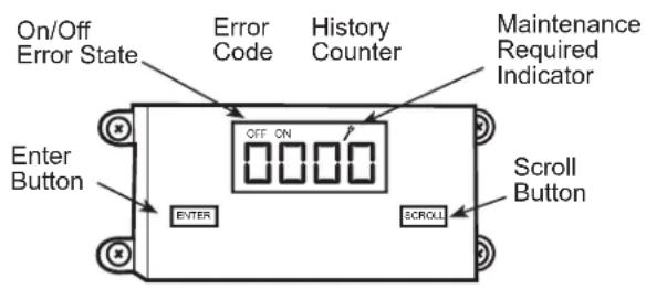
Check Error Codes:
- Press the ENTER key to activate the display.
- Each press of the scroll key display the next error code.
Clear History Counters:
- Press and hold the ENTER key and SCROLL KEY for about 6 seconds.
| Error Code | Problem Action | |
| 1 | Front panel button stuck for more than 20 seconds | Continue to monitor for "OPEN" (unstuck) switch. Do not process switch input. |
| 2 | Input voltage out of specification (103-127/187-253) | Unit stops, open all relays until voltage is back within specs then resumes operation |
| 3 | Indoor temperature sensor is open or shorted | Unit defaults to 75°F in COOLING or 68°F in HEATING and will continue to operate. |
| 4 | Indoor coil temperature sensor is open or shorted | The unit's control board defaults 40°F. It will override the sensor and the unit will continue to operate. |
| 5 | Outdoor coil temperature sensor is open or shorted | The unit defaults to 20°F, overriding the sensor. The unit will continue to operate. Using Electric heat if available for HEATING. If not available, it will use HEAT PUMP if the outdoor temperature allows. |
| 6 | Outdoor coil > (greater than) 175°F | The unit will shut down for 5 minutes, resume operation for 3 minutes. If test fails 3 times, the severity is increased and the unit operation is locked out. |
| 7 | Indoor coil < (less than) 30°F for 2 consecutive minutes | The compressor will turn off and the High Fan speed will run. When coil temp reaches 45°F the unit will resume operation after lockout time. |
| 8 | Unit cycles > (greater than) 9 times per hour | The unit will continue to operate and be monitored. |
| 9 | Unit cycles < (less than) 3 times per hour The unit will continue to operate and be monitored. | |
| 10 | Room freeze protection | Only use if Electric Heat is available. Run High Speed and Electric Heat until room temperature reaches 46°F. The unit will display "FRZ" during operation. Logged only. |
| 11 | Wall stat problem or connection issue | The unit will not operate. |
| 12 | Not applicable Not applicable | If using is cooling or heat pump is on, shut down compressor. Run high fan until switch closes, then resume operation. The third occurrence in 1 hour locks unit out. Applicable to 24K unit only. |
| 13 | High pressure limit switch is open | If using is cooling or heat pump is on, shut down compressor. Run high fan until switch closes, then resume operation. The third occurrence in 1 hour locks unit out. Applicable to 24K unit only. |
| 14 | Not applicable Not applicable | If indoor coil temperature is less than ambient temperature for 3 minutes the unit will use electric heat to satisfy the heating demand. |
| 15 | Heat pump error | Occurs if the ambient temperature range falls below 0°F or greater than 130°F. The error code will remain on until the temperature reaches the operating range and then the unit will return to normal operation. |
| 16 | Temperature beyond operating limits | The compressor must be enabled and have at least 2 fan speeds. |
| 17 | Equipment doesn't meet minimum configuration | The compressor must be enabled and have at least 2 fan speeds. |
| 18 | Not applicable Not applicable | Not applicable |
| 19 | Not applicable Not applicable | Not applicable |
| 20 | Not applicable Not applicable | Not applicable |
| 21 | Not applicable Not applicable | Not applicable |
| 22 | Outdoor coil temperature <30°F for 2 consecutive minutes | Unit will use electric heat to satisfy heating demands until the temperature equals or exceeds 45°F. Applicable for the Heat Pump models only. |
| 23 | Not applicable Not applicable | Not applicable |
| 24 | Not applicable Not applicable | Not applicable |
Notes
Follow these three steps to protect your new appliance investment:
1 Complete and mail your Consumer Production Registration today. Have the peace of mind of knowing we can contact you in the unlikely event of a safety modification.
After mailing the registration below, store the document in a safe place. It contains information you will need to read about you. Your service number is 844-GE4-PTAC (or 844-434-7822).
Read your Owner's Manual carefully. It will help you operate your new appliance properly.

CONSUMER PRODUCT OWNERSHIP REGISTRATION
cut here
Product:
Model:
Serial:
Three ways to register your appliance:


SCAN
this code with yoursmartphone app

GO ONLINE
pliances.com/register

COMPLETE & MAIL
this registration card
Mr. Mrs. Ms.
First Name
Street Address
Email Address
1
We'll use your email address to send you information about your product, as well as discounts and other offers from GE Appliances
City
Month


Phone Number

Revised 6/15
245D1499P001
Date appliance was installed or placed in use
GE Appliances takes your privacy seriously. All information you provide shall be held in strict accordance with the GE Appliances Privacy Policy. Read the full policy at www.geappliances.com/privacy/privacy_policy.htm.
geappliances.com/register

cut here
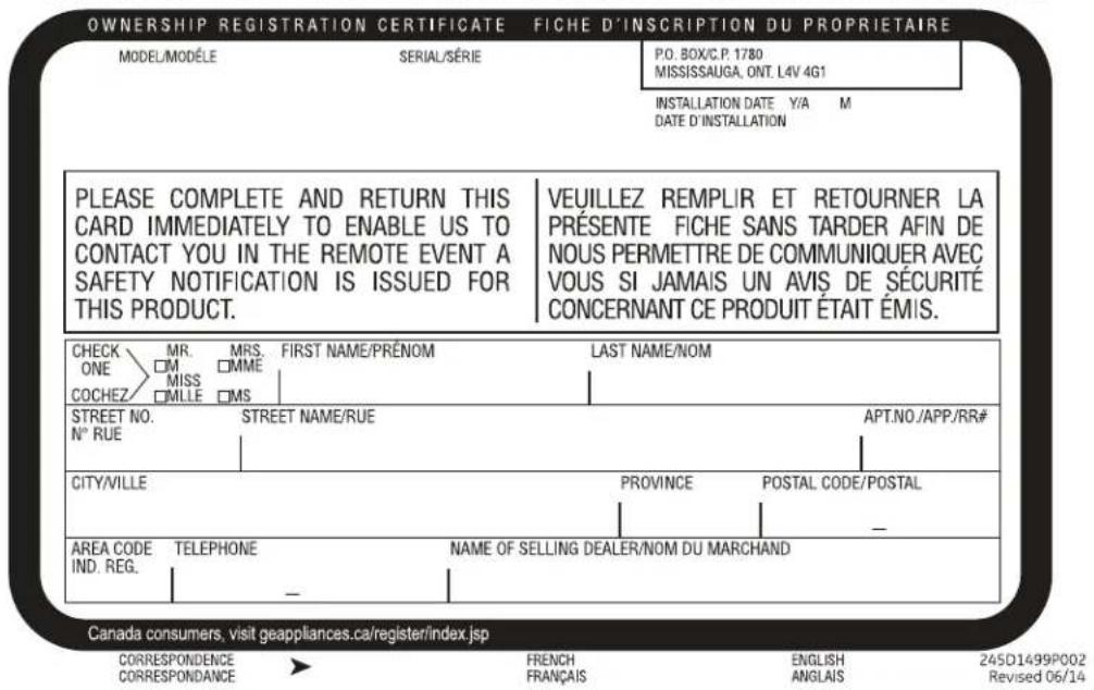
FOR CANADIAN CONSUMERS / POUR LES CONSOMMATEURS CANADIENS
Please place in envelope and mail to:
PRODUCT REGISTRATION DEPARTMENT
POBOX34980
LOUISVILLE KY 40232-4980
Please place in envelope and mail to:
GE Appliances Vertical Zoneline Limited Warranty
All warranty service provided by our Factory Service Centers or an authorized Customer Care * technician. To schedule service, on-line, visit us at GEAppliances.com, or call 844-GE4-PTAC (or 844-434-7822)). For service in Canada, contact Gordon Williams Corp. at 1.888.209.0999. Please have serial number and model number available when calling for service.
| For The Period Of: GE | Will Replace: |
| One Year From the date of the original purchase | Any part of the air conditioner which fails due to a defect in materials or workmanship. During this limited one-year warranty, GE will provide, free of charge, all labor and related service cost to replace the defective part. |
| Five Year From the date of the original purchase | Sealed Refrigerating System, if any part of the sealed refrigerating system (the compressor, condenser, evaporator and all connecting tubing including the make up air system) should fail due to a defect in materials or workmanship. During this limited five-year warranty, GE will provide, free of charge, all labor and related service cost to replace the defective part. |
| Second through Fifth Year From the date of the original purchase | For the second through the fifth year from the date of original purchase, GE will replace certain parts that fail due to a defect in materials or workmanship. Parts covered are fan motors, switches, thermostats, electric resistance heater, electric resistance heater protectors, compressor overload, solenoids, circuit boards, auxiliary controls, thermistors, frost controls, ICR pump, capacitors, varistors and indoor blower bearing. During this four-year limited additional warranty, you will be responsible for any labor or on-site service costs. |
What GE Will Not Cover:
Service trips to your site to teach you how to use the product.
- Improper installation, delivery or maintenance. If you have an installation problem, or if the air conditioner is of improper cooling capacity for the intended use, contact your dealer or installer. You are responsible for providing adequate electrical connecting facilities.
In commercial locations, labor necessary to move the unit to a location where it is accessible for service by an individual technician.
Failure or damage resulting from corrosion due to installation in an environment containing corrosive chemicals.
- Replacement of fuses or resetting of circuit breakers.
Failure of the product resulting from modifications
to the product or due to unreasonable use, including failure to provide reasonable and necessary maintenance.
Failure or damage resulting from corrosion due to installation in a coastal environment, except for models treated with special factory-applied anti-corrosion protection as designated in the model number.
- Damage to product caused by improper power supply voltage, accident, fire, floods or acts of God.
- Incidental or consequential damage to personal property caused by possible defects with this air conditioner.
Damage caused after delivery.
Product not accessible to provide required service.
EXCLUSION OF IMPLIED WARRANTY--Your sole and exclusive remedy is product repair as provided in this Limited Warranty. Any implied warranties, including the implied warranties of merchantability or fitness for a particular purpose, are limited to one year or the shortest period allowed by law.
This limited warranty is extended to the original purchaser and any succeeding owner for products purchased for use within the USA and Canada. If the product is located in an area where service by a GE Appliances Authorized Servicer is not available, you may be responsible for a trip charge or you may be required to bring the product to an Authorized GE Appliances Service location for service. In Alaska, the warranty excludes the cost of shipping or service calls to your site.
Some states or provinces do not allow the exclusion or limitation of incidental or consequential damages. This warranty gives you specific legal rights, and you may also have other rights which vary from state to state or province to province. To know what your legal rights are, consult your local, state or provincial consumer affairs office or your state's Attorney General.
Consumer Support
GE Appliances Website
Have a question or need assistance with your appliance? Try the GE Appliances Website 24 hours a day, any day of the year! You can also shop for more great GE Appliances products and take advantage of all our on-line support services designed for your convenience. In the US: GEAppliances.com
Register Your Appliance
Register your new appliance on-line at your convenience! Timely product registration will allow for enhanced communication and prompt service under the terms of your warranty, should the need arise. You may also mail in the pre-printed registration card included in the packing material. In the US: GEAppliances.com/register
Schedule Service
Expert GE Appliances repair service is only one step away from your door. Get on-line and schedule your service at your convenience any day of the year. In the US: GEAppliances.com/ge/service-and-support/service.htm or call 800.432.2737 during normal business hours.
Extended Warranties
Purchase a GE Appliances extended warranty and learn about special discounts that are available while your warranty is still in effect. You can purchase it on-line anytime. GE Appliances Services will still be there after your warranty expires. In the US: GEAppliances.com/ge/service-and-support/shop-for-extended-service-plans.htm or call 800.626.2224 during normal business hours.
Parts and Accessories
Individuals qualifed to service their own appliances can have parts or accessories sent directly to their homes (VISA, MasterCard and Discover cards are accepted). Order on-line today 24 hours every day. In the US: GEApplianceparts.com or by phone at 877.959.8688 during normal business hours.
Instructions contained in this manual cover procedures to be performed by any user. Other servicing generally should be referred to qualified service personnel. Caution must be exercised, since improper servicing may cause unsafe operation.
Contact Us
If you are not satisfied with the service you receive from GE Appliances, contact us on our Website with all the details including your phone number, or write to:
In the US: General Manager, Customer Relations | GE Appliances, Appliance Park | Louisville, KY 40225
GEAppliances.com/ge/service-and-support/contact.htm
vertical Zoneline
CONSIGNES DE SECURITE 3
UTILISATION DU ZONELINE
Raccordements electriques 17, 18
LiTe de verificacion de I installation 18
$$ A Z 9 1 H 0 9 = 3 5 0 $$
$$ A Z 9 1 H 1 2 = 4 1 0 $$
- See NEC for application for 265 Volts.
FINALISATION DE L'INSTALLATION
LISTE DE VERIFICATION DE L'INSTALLATION
Three ways to register your appliance:
Product:
Model:
Serial:


SCAN
this code with yoursmartphone app

GO ONLINE
pliances.com/register

COMPLETE & MAIL
this registration card
Mr. Mrs. Ms.
First Name Last Name
Street Address Apt.#
Email Address
We'll use your email address to send you information about your product, as well as discounts and other offers from GE Appliances
City State Zip Code
Month Day Year Phone Number ( )
Date appliance was installed or placed in use
GE Appliances takes your privacy seriously. All information you provide shall be held in strict accordance with the GE Appliances Privacy Policy. Read the full policy at www.geappliances.com/privacy/privacy_policy.htm.
geappliances.com/register
Revised 6/15
245D1499P001
Decouperici
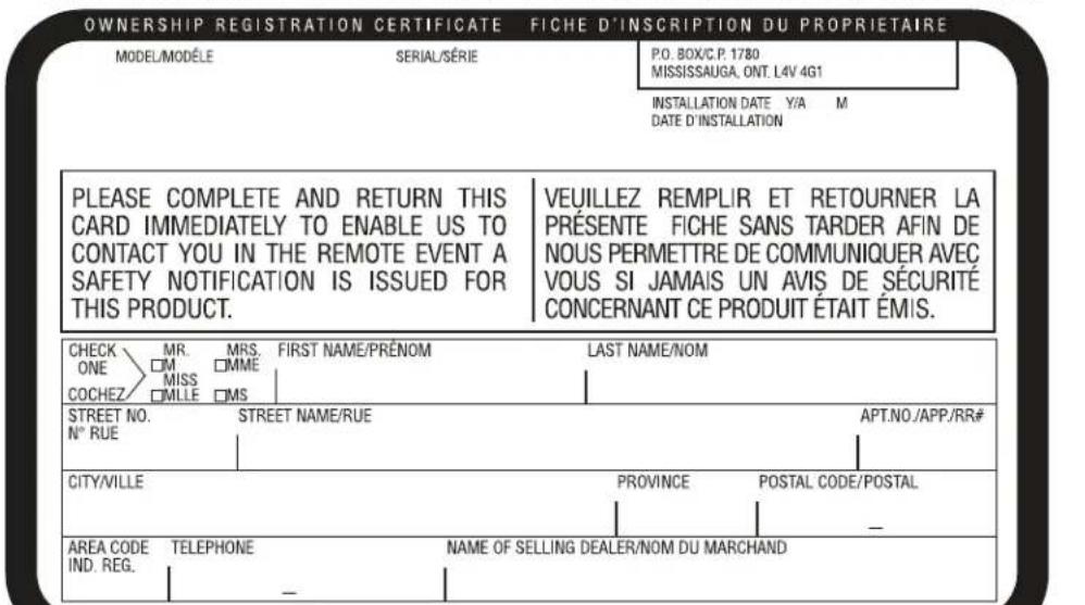
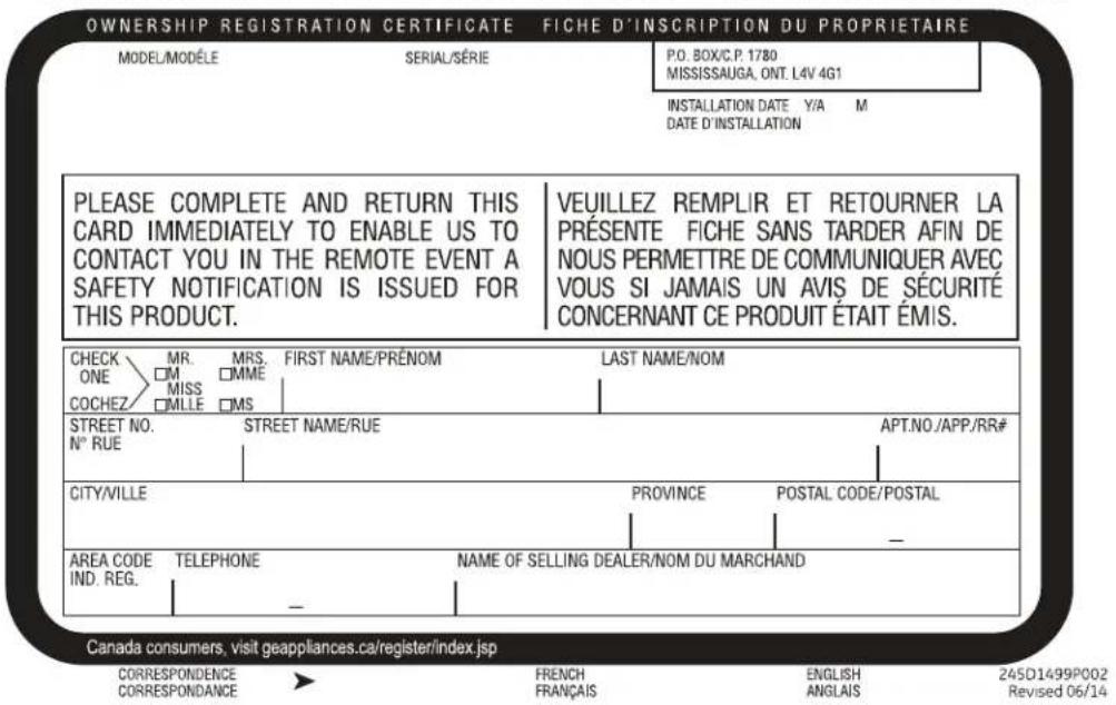
FOR CANADIAN CONSUMERS / POUR LES CONSOMMATEURS CANADIENS
Canada consumers, visit geappliances.ca/register/index.jsp
CORRESPONDENCE
CORRESPONDANCE
FRENCH
FRANÇAIS
ENGLISH
ANGLAIS
245D1499P002
Revised 06/14
Please place in envelope and mail to:
PRODUCT REGISTRATION DEPARTMENT
POBOX34980
LOUISVILLE KY 40232-4980
Please place in envelope and mail to:
Garant : GE Appliances, a Haier company
Louisville, KY 40225
Au Canada: Prodsupport.mabe.ca/crm/Products/ProductRegistration.aspx
Au Canada: GEAppliances.ca/en/support/service-request ou composez le 800.561.3344
Prolongation de garantie
Au Canada: GEAppliances.ca/en/support/purchase-extended-warranty ou composez le 800.290.9029
Connectivite a distance
GEAppliances.com/ge/service-and-support/contact.htm
Au Canada : Director, Consumer Relations, Mabe Canada Inc. | Suite 310, 1 Factory Lane | Moncton, N.B. E1C 9M3 GEAppliances.ca/en/contact-us
$$ A Z 9 1 H 0 9 = 3 5 0 $$
$$ A Z 9 1 H 1 2 = 4 1 0 $$
AWG - American Wire Gauge
- See NEC for application for 265 Volts.
INSTALACION FINAL
Three ways to register your appliance:


SCAN
this code
with your
smart
phone app

GO ONLINE
geappliances.com/register

COMPLETE & MAIL
this registration card
Mr. Mrs. Ms.
First Name
Street Addre
Email Address
1
We'll use your email address to send you information about your product, as well as discounts and other offers from GE Appliances
City
Month
geappliances.com/register

Day
Year
Phone Number
- ba + b = - dc + d
Date appliance was installed or placed in use
GE Appliances takes your privacy seriously. All information you provide shall be held in strict accordance with the GE Appliances Privacy Policy. Read the full policy at www.geappliances.com/privacy/privacy_policy.htm.
Revised 6/15
245D1499P001

cut here
FOR CANADIAN CONSUMERS / POUR LES CONSOMMATEURS CANADIENS
Please place in envelope and mail to:
PRODUCT REGISTRATION DEPARTMENT
POBOX34980
LOUISVILLE KY 40232-4980
Please place in envelope and mail to:
Louisville, KY 40225