SHI4HCS48E - Dishwasher BOSCH - Free user manual and instructions

Find the device manual for free SHI4HCS48E BOSCH in PDF.

BOSCH SHI4HCS48E - Dishwasher
📄 989 pages English EN Download 💬 AI Question 10 questions ⚙️ Specs
Notice BOSCH SHI4HCS48E - page 210
Pick your language and provide your email: we'll send you a specifically translated version.
Brand Bosch
Model SHI4HCS48E
Product type Fully integrated built-in dishwasher
Dimensions (H x W x D) 86.5 x 60 x 57 cm (estimated)
Weight Approximately 45 kg
Electrical supply 220-240 V, 50 Hz, 10 A
Power consumption 2400 W (estimated)
Capacity 14 place settings
Number of programs 6 programs (Eco, Intensive, Quick, etc.)
Special functions VarioDrawer, EmotionLight, TimeLight, Gap illumination
Drying system PerfectDry with zeolite heat exchanger
Spray arms 3 arms (upper, lower, cookware)
Filter Self-cleaning 3-piece filter
Control panel Electronic touch, LED display
Noise level 44 dB(A) (estimated)
Energy class D (scale A-G)
Water consumption per cycle 9.5 L (approx.)
Maintenance and cleaning Washable filters, removable spray arms, replaceable door seal
Safety Child safety, anti-overflow protection, door lock
Spare parts and repairability Many user-replaceable parts (worktop, basket, arm, filters, cord, etc.)
General information Repair instructions available in several languages, assembly guide for spare parts

Frequently Asked Questions - SHI4HCS48E BOSCH

How to install the SHI4HCS48E dishwasher?
Installation must be carried out by a qualified professional. Ensure compliance with the electrical and hydraulic connections described in the manual. The worktop can be removed to facilitate built-in installation.
What wash programs are available?
This model offers several programs such as Eco, Intensive, Quick, Silent, and a glass program. Refer to the program table in the manual for details.
How to clean the filters?
Turn the coarse filter counterclockwise, remove the filter system. Clean under running water. Ensure the locking clips engage when reassembling.
What to do if the dishwasher does not start?
First check the power supply and that the door is properly closed. Consult the error code section in the manual. If the problem persists, contact after-sales service.
Can I repair parts like the power cord myself?
Yes, this model is designed to allow user replacement of certain parts, such as the power cord, filters, and spray arms. Follow the instructions in the manual and respect safety guidelines (disconnect the appliance 60 seconds before).
How to replace a worn door seal?
The lower seal is removed after taking off the retaining clips. The upper seal must be cut to the correct length (1750 mm for 81 cm height, 1850 mm for 86 cm). Position it correctly by aligning the white dot.
What does EmotionLight mean?
EmotionLight projects a light on the floor to indicate the cycle status (e.g., a steady light for cycle end). It can be replaced in case of malfunction.
How to adjust the dishwasher feet?
The feet are height-adjustable. For the base panel, unclip it from underneath with a screwdriver, then adjust the feet before replacing the panel.
What types of detergent to use?
Use a dishwasher detergent in powder, gel, or tablet form. The detergent compartment is designed for standard products. Follow the dosages indicated on the packaging.
Where to find the serial number for spare parts?
The serial number (E-NR) is on the rating plate located on the side of the door or at the back of the appliance. It is necessary to order original spare parts.

User questions about SHI4HCS48E BOSCH

0 question about this device. Answer the ones you know or ask your own.

Ask a new question about this device

Your email remains private: it is only used to notify you if someone answers your question.

No questions yet. Be the first to ask one.

Download the instructions for your Dishwasher in PDF format for free! Find your manual SHI4HCS48E - BOSCH and take your electronic device back in hand. On this page are published all the documents necessary for the use of your device. SHI4HCS48E by BOSCH.

USER MANUAL SHI4HCS48E BOSCH

  1. Повдигнете леко работния плот отпред. (3).
  2. Избутайте работния плот назад (4).
  3. Свалете работния плот.

2021-03-22_9001630792 Copyright by BSH Hausgeräte GmbH Страница 8 от 989

  1. Сгънете фиксатора.

Mechanical diagram showing a lever mechanism with a curved arrow indicating rotational motion (no text or symbols present)

2021-03-22_9001630792 Copyright by BSH Hausgeräte GmbH Страница 9 от 989

BOSCH SHI4HCS48E - 2

Ремонт

  1. Поставете предметите за миене.

Two diagrams showing a mechanical device being lifted by a spring, with no visible text or symbols.

BOSCH SHI4HCS48E - Ремонт - 2

Ремонт

BOSCH SHI4HCS48E - Ремонт - 1

Ремонт

3.

Diagram showing a hand inserting a screw into a device with a magnified view of the screw and its insertion direction.

BOSCH SHI4HCS48E - Ремонт - 2

Ремонт

Изискване:

2021-03-22_9001630792 Copyright by BSH Hausgeräte GmbH Страница 22 от 989

BOSCH SHI4HCS48E - Изискване: - 1

Ремонт

  1. Повдигнете панела.

2021-03-22_9001630792 Copyright by BSH Hausgeräte GmbH Страница 26 от 989

BOSCH SHI4HCS48E - Ремонт - 1

Ремонт

4.

Mechanical assembly diagram showing a red lever mechanism with labeled parts (1 and 2), no readable text or symbols present.

BOSCH SHI4HCS48E - Ремонт - 2

Ремонт

BOSCH SHI4HCS48E - Ремонт - 1

Ремонт

3D diagram of a mechanical component with red and black arrows indicating directional flow (no text or symbols)

BOSCH SHI4HCS48E - Ремонт - 2

Ремонт

2.

Close-up of a red mechanical bracket with green cable and arrow indicating connection (no text or symbols)

2021-03-22_9001630792 Copyright by BSH Hausgeräte GmbH Страница 33 от 989

BOSCH SHI4HCS48E - Ремонт - 2

Ремонт

BOSCH SHI4HCS48E - Ремонт - 1

Ремонт

4.

Pure technical line drawing of curved structural elements without any text or symbols

BOSCH SHI4HCS48E - Ремонт - 2

Ремонт

4.21 Смяна на EmotionLight

Technical diagram showing a mechanical assembly with labeled parts and directional arrows indicating movement or assembly.

  1. Свалете EmotionLight от уреда.

BOSCH SHI4HCS48E - Смяна на EmotionLight - 2

Ремонт

BOSCH SHI4HCS48E - Ремонт - 1

Ремонт

Close-up of a mechanical component with a red vertical stripe and black arrow indicating a cut or section (no text or symbols visible)

BOSCH SHI4HCS48E - Ремонт - 2

Ремонт

  1. Malo podignite radnu ploču s prednje strane (3).
  2. Gurnite radnu ploču prema stražnjoj strani (4).
  3. Uklonite radnu ploču.

4.1.2 Postavljanje radne ploče

  1. Uklopite stražnji dio radne ploče u vodilice s pomoću pričvrsnih spojnica (1).
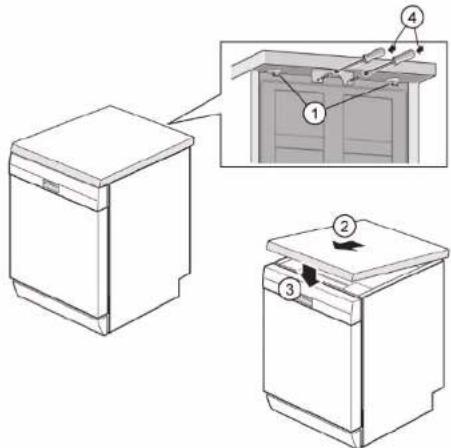
Diagram showing three views of a kitchen appliance with numbered components and an inset view highlighting a cabinet interior.

  1. Gurnite radnu ploču prema naprijed (2).
  2. Pritisnite prednji dio radne ploče prema dolje dok se obje zahvatne poluge čujno ne uklope na mjesto (3).
  3. Ponovno zavmite dva vijka (4) (opcionalno).

BOSCH SHI4HCS48E - Postavljanje radne ploče - 2

Popravak

4.2 Postavljanje sustava košare

Zahtjev:

√ Košara je uklonjena iz uredaja.

4.2.1 Postavljanje vodilice za tablete za model od 86 cm Specijalni alati:

Vodilica za tablete [00614935]

Držač za šalice [00618565]

2021-03-22_9001630792 Autorska prava BSH Hausgeräte GmbH Stranica 50 od 989

BOSCH SHI4HCS48E - Postavljanje vodilice za tablete za model od 86 cm Specijalni alati: - 1

Popravak

  1. Postavite predmete za pranje.

Two diagrams showing a mechanical device being lifted by a spring, with no visible text or symbols.

4.2.3 Postavljanje umetka za parnu pećnicu Specijalni alati:

Vodilica za tablete [00614935]
Držač za šalice [00618565]

- Pričvrstite umetak za parnu pećnicu s krajnjim dijelovima ispod sustava košare.
Technical diagram illustrating a multi-step installation or installation process with labeled steps and structural details.

BOSCH SHI4HCS48E - Popravak - 3

Popravak

4.3 Zamjena ladice varioDrawer

4.3.1 Uklanjanje ladice varioDrawer

  1. Savijte preklope ručice prema unutra.

3D architectural diagram of a steel-framed building facade with structural grid and window grilles, showing a close-up inset of a blue door detail (no text or symbols)

  1. Uklonite ručicu prema gore.

  2. Pritisnite plastične bočne umetke prema van i izvadite ih prema gore iz okvira.
Two blue industrial equipment components with metal railings and directional arrows indicating motion (no text or symbols)

Popravak

  1. Pažljivo savijte jezičce vodilice prema van.
3D architectural diagram showing structural grid and rebar layout with labeled components (no text or symbols present)

  1. Izvucite sklopive nosače iz jezičaca.

  2. Pritisnite i izvadite metalni okvir s prednje strane iz držača.
3D diagram of a mechanical assembly with blue structural elements and directional arrows indicating motion (no text or symbols)

  1. Gurnite i izvadite metalni okvir sa stražnje strane iz vodilice.

4.3.2 Postavljanje ladice varioDrawer

4.4.2 Postavljanje prskalice

  1. Umetnite donju prskalicu.
    Prskalica se uklapa u položaj.
  2. Umetnite gornju prskalicu i pričvrstite je.

BOSCH SHI4HCS48E - Postavljanje prskalice - 1

Popravak

4.5 Zamjena filtara

4.5.1 Uklanjanje filtra

Pazite da u sifon ne dospiju strana tijela.

  1. Povucite mikrofilter prema dolje da biste ga uklonili.
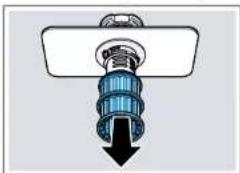
Diagram of a mechanical component with a downward arrow indicating force or direction (no text or symbols present)

4.5.2 Postavljanje filtara

  1. Ponovno sastavite sustav filtra.

4.7.2 Priključivanje kabela za napajanje

BOSCH SHI4HCS48E - Priključivanje kabela za napajanje - 1

POZOR!

  1. Umetnite kratki kraj opruge u otvor za postavljanje poklopca za deterdžent (2).
  2. Pritisnite poklopac na dozator (3).
  1. Podignite poklopac pumpe prema unutra pod kutom i uklonite ga.

4.9.2 Postavljanje poklopca pumpe za otpadnu vodu

▶ Umetnite poklopac pumpe (1) i pritisnite ga (2).
① ② CLICK

Poklopac pumpe uklapa se u položaj.

BOSCH SHI4HCS48E - Postavljanje poklopca pumpe za otpadnu vodu - 2

Popravak

4.10 Zamjena bočne ploče

Zahtjev:

Sl. 1: Potpuno integrirano
Technical diagram of a refrigerator interior with numbered components and directional arrows indicating rotation or movement.

  1. Nagnite bočnu ploču malo prema van pri vrhu (2).
  2. Spustite bočnu ploču i izvucite je iz kanala postolja (3).

BOSCH SHI4HCS48E - Zahtjev: - 2

Popravak

Sl. 2: Potpuno integrirano

Technical diagram showing a mechanical assembly with numbered components and directional arrows indicating motion or assembly.

  1. Pritisnite bočnu ploču na uređaj (2).
  2. Pričvrstite bočnu ploču vijcima (3).

BOSCH SHI4HCS48E - Popravak - 2

Popravak

3.

BOSCH SHI4HCS48E - Popravak - 1

Osigurajte vrata tako da ih držite s jedne strane.

Uklonite dva vijka.
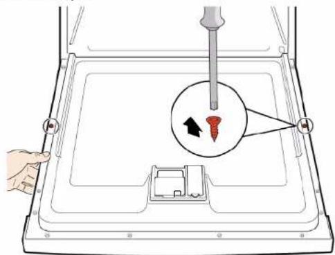
Diagram showing a hand inserting a screw into a device with a magnified view of the screw and its insertion direction.

BOSCH SHI4HCS48E - Popravak - 3

Popravak

Zahtjev:

BOSCH SHI4HCS48E - Zahtjev: - 1

Popravak

  1. Uklonite kontrolnu ploču.
    1. Lagano otvorite vrata (1).
  1. Pričvrstite u utor kanala postolja (2).

  2. Polako zatvorite vrata (3).

Technical diagram showing assembly steps of a mechanical component with numbered annotations indicating process flow.

Sustav kabela automatski se pričvršćuje na zglob vrata.

BOSCH SHI4HCS48E - Popravak - 2

Popravak

    1. Lagano zatvorite vrata (4).
  1. Pomaknite utor prema natrag i otpustite zglob vrata (5).

  2. Otvorite vrata (6).

Technical diagram showing assembly steps of a mechanical component with numbered annotations indicating process flow.

  1. Podignite i skinite ploču.

  2. Uklonite nogicu prema naprijed (1).

Mechanical assembly diagram showing red components mounted on a gray frame, with numbered callouts (1) indicating specific parts (no text or symbols present)

4.14.2 Postavljanje donje ploče

BOSCH SHI4HCS48E - Postavljanje donje ploče - 1

Popravak

4.

BOSCH SHI4HCS48E - Popravak - 1

Ovisno o seriji modela, utikač za EmotionLight još je pričvršćen na postolje.

Deblokirajte utikač na zahvatnom podizaču i gurnite ga prema natrag (opcionalno) (2).

4.15.2 Postavljanje ploče postolja

  1. Otpustite zahvatni element na vrhu.

3D mechanical assembly diagram showing internal components and a red component (no text or symbols)

    1. Umetnite odvijač ispod metalne stezaljke (1).
  1. Nježno otpustite metalnu kopču (2).

Mechanical assembly diagram showing a lever mechanism with labeled parts (1 and 2), no readable text or symbols present.

BOSCH SHI4HCS48E - Postavljanje ploče postolja - 3

Popravak

  1. Podignite i skinite preljevnu cijev.

3D mechanical assembly diagram showing a red component with mounting holes and a central hub (no text or symbols visible)

4.16.2 Postavljanje preljevne cijevi

Technical diagram showing mechanical assembly with numbered components and directional arrows indicating motion or assembly steps.

BOSCH SHI4HCS48E - Postavljanje preljevne cijevi - 2

Popravak

3D diagram of a mechanical component with red and black arrows indicating directional flow (no text or symbols)

  1. Pričvrstite metalnu kopču s lijeve i desne strane.
Mechanical assembly diagram showing a tool inserted into a component with a red component, no visible text or symbols

BOSCH SHI4HCS48E - Popravak - 3

Popravak

  1. Pričvrstite zglob vrata vijcima.
  2. Postavite unutarnja vrata na zglob vrata.
  3. Pričvrstite unutarnja vrata vijcima.

4.17.2 Postavljanje unutarnjih vrata

4.18.2 Postavljanje zgloba vrata

BOSCH SHI4HCS48E - Postavljanje zgloba vrata - 1

OPASNOST Opasnost od strujnog udara zboč U slučaju nepravilnog popravka mnoj udara ► Električne dijelove mora po ► Nakon popravka provedite n nacionalnim propisima.

2021-03-22_9001630792 Autorska prava BSH Hausgeräte GmbH Stranica 73 od 989

BOSCH SHI4HCS48E - Postavljanje zgloba vrata - 3

Popravak

    1. Postavite zglob na uređaj (1).
  1. Pomaknite zglob prema dolje (2) dok se ne pričvrsti na uređaj.
Technical diagram showing mechanical assembly with numbered components and directional arrows indicating motion or movement.

2.

BOSCH SHI4HCS48E - Popravak - 2

Uzemljenje koje nedostaje može dovesti do električnog potencijala na vratima.

Uspostavite uzemljenje.
Close-up of a red mechanical bracket with green cable and arrow indicating assembly (no text or symbols)

BOSCH SHI4HCS48E - Popravak - 4

Popravak

4.19 Zamjena (donje) brtve vrata

Zahtjev:

Uredaj je isključen iz napajanja.
Uređaj je isključen iz priključka za dovod vode.
√ Vanjska su vrata uklonjena.
Ploča postolja je uklonjena.→68
Donja ploča je uklonjena (opcionalno).→67
√ Opruge vrata su uklonjene.
Kontrolna je ploča uklonjena.
Držač kabelskog snopa na donjoj desnoj strani je uklonjen.

4.19.1 Uklanjanje brtve vrata

  1. Podignite i skinite preljevni slivnik.
3D mechanical assembly diagram showing internal components and a central hub (no text or symbols visible)

BOSCH SHI4HCS48E - Uklanjanje brtve vrata - 2

Popravak

4.19.2 Postavljanje brtve vrata

4.

BOSCH SHI4HCS48E - Postavljanje brtve vrata - 1

Brtva ne smije biti valovita ili rastegnuta u kutovima. Brtva se prekida dijagonalno na krajevima i sužava se na dnu spremnika s prednje strane.

BOSCH SHI4HCS48E - Postavljanje brtve vrata - 2

Popravak

4.21 Zamjena modula EmotionLight

Diagram showing a device's internal components with numbered annotations indicating parts of the main body and parts of the door.

  1. Uklonite EmotionLight iz uređaja.

4.21.2 Postavljanje modula EmotionLight

  1. Umetnite držač u okvir spremnika sredstva za ispiranje (1).
Technical diagram showing a device's internal components with numbered annotations indicating parts of the main body and parts of the rear panel.

BOSCH SHI4HCS48E - Postavljanje modula EmotionLight - 2

Popravak

  1. Postavite zahvatnu kuku (2).

3.

BOSCH SHI4HCS48E - Popravak - 1

POZOR!

BOSCH SHI4HCS48E - POZOR! - 1

Popravak

Close-up of a mechanical component with a red vertical stripe and black arrow indicating a cut or section (no text or symbols visible)

Sl. 3: Ravni kabel

  1. Ukopčajte utikač.

BOSCH SHI4HCS48E - Popravak - 2

Popravak

4.22 Zamjena modula TimeLight

Technical diagram showing a mechanical assembly with numbered components and highlighted parts, likely illustrating a machining or assembly process.

  1. Povucite modul TimeLight prema gore i izvucite ga iz vodilice (2).

4.22.2 Postavljanje modula TimeLight

  1. Savijte zahvatne elemente (1) ponovno prema natrag.
Technical diagram showing a red structural component with numbered annotations (1 and 2) indicating parts of a mechanical assembly.

  1. Gurnite modul TimeLight u vodilicu (2).
  2. Priključite električni priključak.

BOSCH SHI4HCS48E - Postavljanje modula TimeLight - 2

Popravak

4.23 Zamjena Gap illumination

Zahtjev:

Uredaj je isključen iz napajanja.
Uređaj je isključen iz priključka za dovod vode.
√ Vanjska vrata su demontirana.
Radna je ploča uklonjena.

4.23.1 Uklanjanje Gap illumination

    1. Odvojite zahvatni element (1).
  1. Uklonite električni priključak s radnog modula (2).
Technical diagram showing a device interior with labeled components and wiring, including numbered annotations 1 and 2.

    1. Odvojite zahvatnu kuku sa stražnje strane (1).
  1. Uklonite vlakno (2).

3D mechanical assembly diagram showing internal components and a directional arrow (no text or symbols)

BOSCH SHI4HCS48E - Uklanjanje Gap illumination - 3

Popravak

    1. Odvojite zahvatnu kuku (1).
  1. Podignite PCB s držačem i uklonite ga iz okvira radnog modula (2).
Technical diagram of a mechanical assembly with numbered components, likely a valve or actuator assembly.

4.23.2 Postavljanje Gap illumination

  1. Umetnite PCB držač u okvir radnog modula.
3D mechanical assembly diagram showing a red component inserted into a housing (no text or symbols visible)

  1. Pritegnite ga dok ne začujete škljocaj.
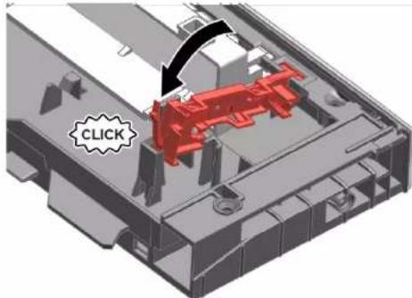
3D mechanical assembly diagram showing a red component inside a transparent housing, with a black arrow indicating a directional movement and a 'CLICK' label (no readable text or symbols beyond the label)

  1. Postavite optičko vlakno i pritegnite ga dok ne čujete škljocaj.
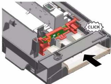
3D mechanical assembly diagram showing internal components with a highlighted 'CLICK' button (no text or symbols beyond label)

  1. Vyklopte držák.

Mechanical diagram showing a lever mechanism with a curved arrow indicating rotational motion (no text or symbols)

2021-03-22_9001630792 Copyright BSH Hausgeräte GmbH strana 91 od 989

BOSCH SHI4HCS48E - Popravak - 6

Oprava

BOSCH SHI4HCS48E - Oprava - 1

Oprava

BOSCH SHI4HCS48E - Oprava - 1

Oprava

4.5.2 Montáž filtrů

3.

Diagram showing a hand inserting a screw into a device with a magnified view of the screw and its insertion direction.

BOSCH SHI4HCS48E - Montáž filtrů - 2

Oprava

Požadavek:

BOSCH SHI4HCS48E - Požadavek: - 1

Oprava

BOSCH SHI4HCS48E - Oprava - 1

Oprava

4.

Mechanical assembly diagram showing a red lever mechanism with labeled parts (1 and 2), no readable text or symbols present.

BOSCH SHI4HCS48E - Oprava - 2

Oprava

BOSCH SHI4HCS48E - Oprava - 1

Oprava

3D diagram of a car door with red and black arrows indicating airflow or movement (no text or symbols)

BOSCH SHI4HCS48E - Oprava - 2

Oprava

2021-03-22_9001630792 Copyright BSH Hausgeräte GmbH strana 114 od 989

2.

Close-up of a red mechanical bracket with green cable and arrow indicating assembly (no text or symbols)

BOSCH SHI4HCS48E - Oprava - 2

Oprava

BOSCH SHI4HCS48E - Oprava - 1

Oprava

4.

Pure technical line drawing of curved pipe or channel sections without any text, numbers, or symbols

BOSCH SHI4HCS48E - Oprava - 2

Oprava

BOSCH SHI4HCS48E - Oprava - 1

Oprava

BOSCH SHI4HCS48E - Oprava - 1

Oprava

Close-up of a mechanical component with a red vertical stripe and black arrow indicating a section (no text or symbols visible)

Obr. 3: Plochý kabel
4. Zasuňte zástrčku.

BOSCH SHI4HCS48E - Oprava - 2

Oprava

BOSCH SHI4HCS48E - Oprava - 1

Oprava

4.23.2 Montáž Gap Illumination

  1. Klap clipsen op.

Mechanical diagram showing a lever mechanism with a curved arrow indicating rotational motion (no text or symbols)

2021-03-22_9001630792 Copyright by BSH Hausgeräte GmbH Side 132 af 989

BOSCH SHI4HCS48E - Montáž Gap Illumination - 2

Reparation

  1. Placér genstandene, der skal vaskes.

Two diagrams showing a mechanical device being lifted by a spring, with no visible text or symbols.

BOSCH SHI4HCS48E - Reparation - 2

Reparation

BOSCH SHI4HCS48E - Reparation - 1

Reparation

4.4.2 Montering af spulearm

4.5.2 Montering af filtre

Fig. 1: Fuldintegreret
Technical diagram of a multi-chamber refrigerator with numbered components and directional arrows indicating internal flow or movement.

Fig. 2: Fuldintegreret
Technical diagram showing a mechanical assembly with numbered components and directional arrows indicating motion or assembly.

  1. Tryk sidepanelet på apparatet (2).
  2. Fastgør sidepanelet med skruer (3).

BOSCH SHI4HCS48E - Montering af filtre - 3

Reparation

3.

Diagram showing a hand inserting a screw into a device with a magnified view of the screw and its insertion direction.

BOSCH SHI4HCS48E - Reparation - 2

Reparation

Preindstilling:

BOSCH SHI4HCS48E - Preindstilling: - 1

Reparation

  1. Afbryd jordkablet (3) (valgfrit).
  2. Åbn apparatets dør.
  3. Hold betjeningspanelet fast for at forhindre det i at falde ned (hold på det).

  4. Fjern de seks skruer.

Diagram of a device interior with screw and control panel, no text or symbols present

  1. Fjern betjeningspanelet.

4.12.2 Montering af betjeningspanel

Mechanical assembly diagram showing a red component with a numbered arrow pointing to a specific part (no text or symbols present)

BOSCH SHI4HCS48E - Montering af betjeningspanel - 2

Reparation

4.

Mechanical assembly diagram showing a red lever mechanism with labeled parts (1 and 2), no readable text or symbols present.

BOSCH SHI4HCS48E - Reparation - 2

Reparation

BOSCH SHI4HCS48E - Reparation - 1

Reparation

3D diagram of a car door with red and black arrows indicating airflow or movement (no text or symbols)

BOSCH SHI4HCS48E - Reparation - 2

Reparation

2.

Close-up of a red mechanical bracket with green cable and arrow indicating connection (no text or symbols)

BOSCH SHI4HCS48E - Reparation - 2

Reparation

BOSCH SHI4HCS48E - Reparation - 1

Reparation

4.

Pure technical line drawing of curved structural elements without any text or symbols

BOSCH SHI4HCS48E - Reparation - 2

Reparation

BOSCH SHI4HCS48E - Reparation - 1

Reparation

  1. Aktivér läsekrogen (2).

3.

BOSCH SHI4HCS48E - Reparation - 1

BEMAERKI

Ukorrekt montering!

BOSCH SHI4HCS48E - Ukorrekt montering! - 1

Reparation

Close-up of a mechanical component with a red vertical stripe and black arrow indicating a cut or section (no text or symbols visible)

Fig. 3: Fladkabel

  1. Sæt stikket i.

BOSCH SHI4HCS48E - Reparation - 2

Reparation

  1. Skub timeLight-modulet ind i føringen (2).
  2. Forbind den elektriske tilslutning.

Reparation

4.23.2 Montering of Gap illumination

  1. Sæt printkortholderen i betjeningsmodules ramme.
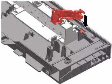
3D mechanical assembly diagram showing a red component inserted into a housing (no text or symbols visible)

BOSCH SHI4HCS48E - Montering of Gap illumination - 2

Reparatie

4.2.3 Steamerinzet monteren

Speciale hulpmiddelen:

Geleider [00614935]
Kopjeshouder [00618565]

BOSCH SHI4HCS48E - Steamerinzet monteren - 1

Reparatie

4.3 varioDrawer vervangen

Reparatie

4.4.2 Sproeiarm monteren

4.5.2 Filters monteren

3.

Diagram showing a hand holding a screwdriver inserted into a device with a magnified inset highlighting the screw and its insertion direction.

BOSCH SHI4HCS48E - Filters monteren - 2

Reparatie

4.11.2 Buitendeur monteren
Technical diagram of a refrigerator interior showing labeled components and directional arrows indicating movement or flow.

4.14.2 Plint monteren

BOSCH SHI4HCS48E - Plint monteren - 1

Reparatie

4.

Mechanical assembly diagram showing a red lever mechanism with labeled parts (1 and 2), no readable text or symbols present.

  1. Maak vergrendelingselement bovenaan los.
3D mechanical assembly diagram showing a sliding mechanism with a red component (no text or symbols visible)

BOSCH SHI4HCS48E - Reparatie - 3

Reparatie

BOSCH SHI4HCS48E - Reparatie - 1

Reparatie

3D diagram of a mechanical component with red and black arrows indicating directional flow or movement (no text or symbols)

Reparatie

4.17 Binnendeur vervangen

Voorwaarde:

4.18.2 Deurscharnier monteren

BOSCH SHI4HCS48E - Deurscharnier monteren - 1

BOSCH SHI4HCS48E - Deurscharnier monteren - 2

GEVAAR

2.

Close-up of a red mechanical bracket with green cable and arrow indicating assembly (no text or symbols)

BOSCH SHI4HCS48E - GEVAAR - 2

Reparatie

4.19 (Onderste) deurafdichting vervangen

Voorwaarde:

Reparatie

4.19.2 De deurafdichting monteren

4.

Pure technical line drawing of curved structural elements without any text or symbols

BOSCH SHI4HCS48E - De deurafdichting monteren - 2

Reparatie

4.21 EmotionLight vervangen

Diagram showing a device's internal components with numbered annotations indicating parts of the main body and adjustment.

BOSCH SHI4HCS48E - EmotionLight vervangen - 2

Reparatie

  1. Koppel de vergrendelingshaak vast (2).

3.

BOSCH SHI4HCS48E - Reparatie - 1

LET OPI

Verkeerde montage!

Reparatie

Close-up of a mechanical component with a red vertical stripe and black arrow indicating a section (no text or symbols visible)

Afb. 3: Platte kabel

  1. Duw de TimeLight-module in de geleiding (2).
  2. Verbind de elektrische aansluiting.

BOSCH SHI4HCS48E - Reparatie - 2

Reparatie

BOSCH SHI4HCS48E - Reparatie - 1

Reparatie

1.2 Explanation of symbols 210

1.2.1 Danger levels.... 210

1.2.2 Hazard symbols 210

1.2.3 Structure of the warnings.... 211

1.2.4 General symbols.... 211

Safety 212

2.1 General Safety instructions 212

2.1.1 All domestic appliances 212

Tools and aids.... 213

Repair 214

4.1 Replacing worktop.... 214

4.1.1 Removing worktop 214

4.1.2 Installing worktop 214

4.2 Installing basket system.... 215

4.2.1 Installing a tab slide for the 86 cm model 215

4.2.2 Installing cup support clip 215

4.2.3 Installing steamer insert 216

4.3 Replacing varioDrawer....217

4.3.1 Removing varioDrawer.... 217

4.3.2 Installing varioDrawer.... 218

4.4 Replacing spray arms 219

4.4.1 Removing spray arm 219

4.4.2 Installing spray arm.... 219

4.5 Replacing filters.... 220

4.5.1 Removing filter 220

4.5.2 Installing filters 220

4.6 Installing baking sheet spray head 221

4.7 Replacing power cord 222

4.7.1 Unplugging power cord.... 222

4.7.2 Plugging in power cord.... 222

4.8 Replacing detergent cover 223

4.8.1 Removing detergent cover 223

4.8.2 Inserting spring.... 223

4.8.3 Installing detergent cover 223

4.9 Replacing wastewater pump cover 224

4.9.1 Removing wastewater pump cover 224

4.9.2 Installing wastewater pump cover 224

4.10 Replacing side panel.... 225

4.10.1 Removing side panel 225

4.10.2 Installing side panel 226

4.11 Replacing outer door 227

4.12 Replacing control panel 229

4.12.1 Removing control panel 229

4.12.2 Installing control panel 229

4.15.1 Removing base socket plate 233

4.15.2 Installing base socket plate 233

4.16 Replacing overflow conduit 234

4.16.1 Removing overflow channel 234

4.16.2 Installing overflow conduit 235

4.17 Replacing inner door 237

4.17.1 Removing inner door 237

4.17.2 Installing inner door 237

4.19 Replacing (lower) door seal 240

4.19.1 Removing the door seal 240

4.19.2 Installing the door seal 241

4.20 Replacing (upper) door seal.... 242

4.20.1 Removing door seal.... 242

4.20.2 Installing door seal.... 242

Repair hints - Dishwasher

4.21 Replacing EmotionLight 243

4.21.1 Removing EmotionLight 243
4.21.2 Installing EmotionLight 243

4.22 Replacing TimeLight 246

4.22.1 Removing TimeLight 246
4.22.2 Installing TimeLight 246

4.23 Replacing Gap illumination.... 247

4.23.1 Removing Gap illumination 247
4.23.2 Installing Gap illumination.... 248

i Concerning this document

1.1 Important information

1.1.1 Purpose

These repair hints support consumer to repair appliances by himself according to the applicable eco-design regulation (as of 03/2021).

They contain information how to exchange defined spare parts including warnings and risks.

In case of questions, please contact our customer service. We will only be liable for damages if the repair hints have been followed properly.

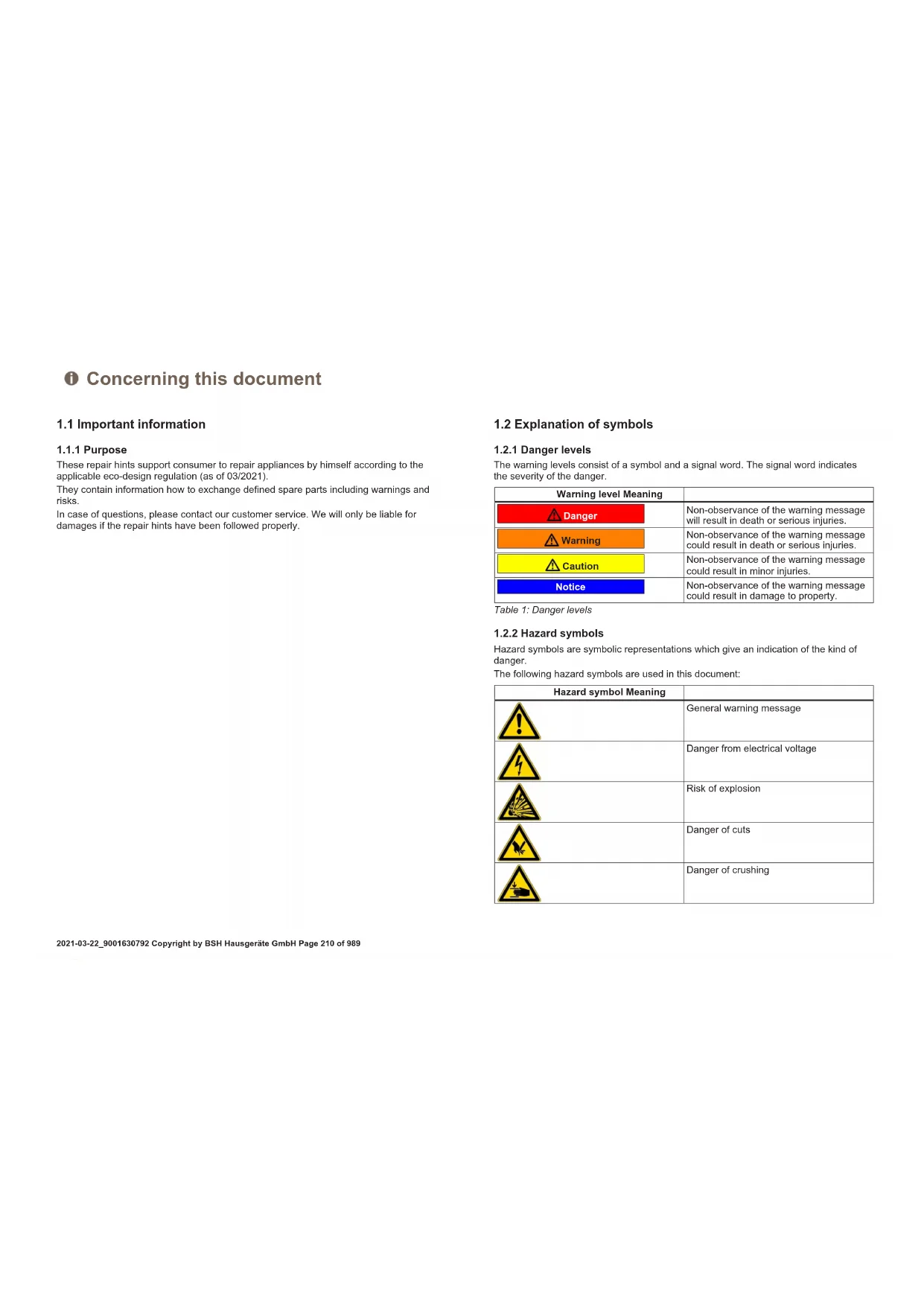
1.2 Explanation of symbols

1.2.1 Danger levels

The warning levels consist of a symbol and a signal word. The signal word indicates the severity of the danger.

Warning level Meaning
DangerNon-observance of the warning message will result in death or serious injuries.
WarningNon-observance of the warning message could result in death or serious injuries.
CautionNon-observance of the warning message could result in minor injuries.
NoticeNon-observance of the warning message could result in damage to property.

Table 1: Danger levels

1.2.2 Hazard symbols

Hazard symbols are symbolic representations which give an indication of the kind of danger.

The following hazard symbols are used in this document:

Hazard symbol Meaning
BOSCH SHI4HCS48E - Hazard symbols - 1General warning message
BOSCH SHI4HCS48E - Hazard symbols - 2Danger from electrical voltage
BOSCH SHI4HCS48E - Hazard symbols - 3Risk of explosion
BOSCH SHI4HCS48E - Hazard symbols - 4Danger of cuts
BOSCH SHI4HCS48E - Hazard symbols - 5Danger of crushing

i Concerning this document

Hazard symbol Meaning
BOSCH SHI4HCS48E - i Concerning this document - 1Danger from hot surfaces
BOSCH SHI4HCS48E - i Concerning this document - 2Danger from strong magnetic field
BOSCH SHI4HCS48E - i Concerning this document - 3Danger from non-ionizing radiation

Table 2: Hazard symbols

1.2.3 Structure of the warnings

Warnings in this document have a standardised appearance and a standardised structure.

BOSCH SHI4HCS48E - Structure of the warnings - 1

BOSCH SHI4HCS48E - Structure of the warnings - 2

Type and source of danger!

Possible consequences of ignoring the danger / warning.

▶ Measures and prohibitions for preventing the danger.

The following example shows a warning that warns against electric shock due to live parts. The measure for avoiding the danger is mentioned.


BOSCH SHI4HCS48E - Structure of the warnings - 3

BOSCH SHI4HCS48E - Structure of the warnings - 4

Risk of electric shock due to live parts!

Death by electrocution

- Disconnect appliances from electrical supply at least 60 seconds before starting repairs.

1.2.4 General symbols

The following general symbols are used in this document:

Gen. symbol Meaning
Identification of a special tip (text and/or graphic)
Identification of a simple tip (only text)
Identification of a link to a video tutorial
Gen. symbol Meaning
Identification of required tools
Identification of required preconditions
Identification of a condition (if ..., then ...)
Identification of a result
StartIdentification of a key or button
[00123456] Identification of a material number
StatusIdentification of displayed text / window(in the appliance's display)

Table 3: General symbols

Safety

2.1 General Safety instructions

2.1.1 All domestic appliances

Risk of electric shock due to live parts!

  • Errors by repairs involving electrical components can lead to electrical shock!
    ■ Disconnect the appliance from the mains for at least 60 seconds before starting work.
    ■ After the repair have a safety test according VDE 0701 or country-specific regulations performed.

Risk of injury from sharp edges!

■ Wear protective gloves.

Risk of crushing during repair, maintenance, troubleshooting and service due to heavy and moving components

■ Wear protective shoes.
■ Secure heavy components from falling down.
■ Do not stick body parts into moving components.

Risk to the appliance's safety / function!

■ Only use original spare parts.

Risk of damage to electrostatically sensitive components (ESDs)!

- Do not touch the modules, including connections and conductor paths.

BOSCH SHI4HCS48E - All domestic appliances - 1

Tools and aids

Designation Details Images
Screwdriver Torx T20 with bore hole [00340764]100 mm, for screws with safety pinBOSCH SHI4HCS48E - Tools and aids - 1
Insulated Screw-driver Torx T15 with bore hole [15000626]Blade length 125 mm, for screws with safety pinBOSCH SHI4HCS48E - Tools and aids - 2
Slotted screwdriverBlade 10 mm x 1.6 mm x 200 mmBOSCH SHI4HCS48E - Tools and aids - 3
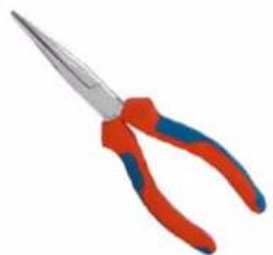
Needle nose pliers [00340871]Length: 200 mm, straightBOSCH SHI4HCS48E - Tools and aids - 4

Repair

4.1 Replacing worktop

Prerequisite:

√ Appliance is disconnected from the power supply.
√ Appliance is freely accessible.

4.1.1 Removing worktop

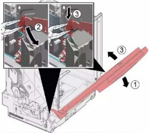
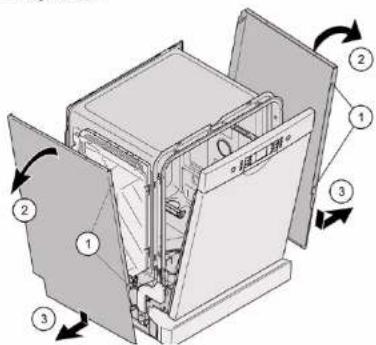
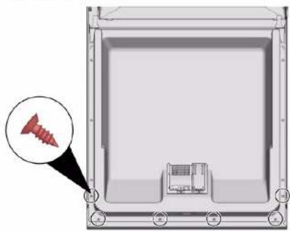
  1. Remove the two screws at the back (1) (optional).
  2. Press both catch levers under the worktop upwards (2).
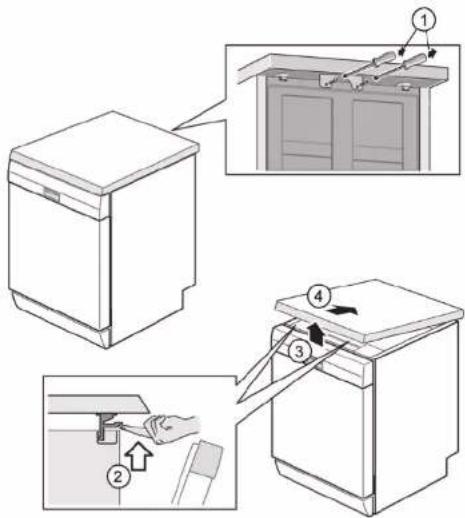
Diagram showing a kitchen appliance with labeled parts and directional arrows indicating assembly or cleaning steps.

  1. Lift the worktop slightly at the front (3).
  2. Push worktop away towards the rear (4).
  3. Remove worktop.

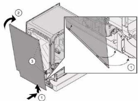
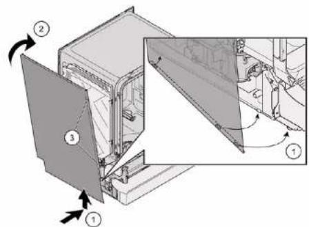
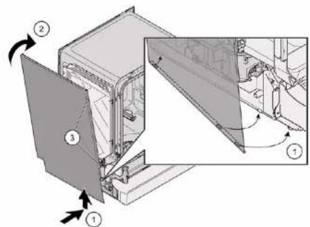
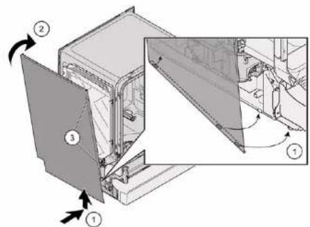
4.1.2 Installing worktop

  1. Lock the rear of the worktop into the guides using the retaining collars (1).
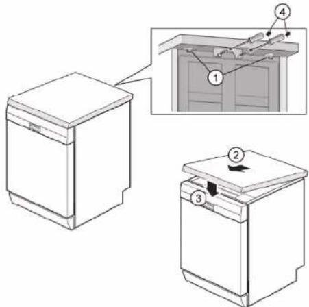
Diagram showing three views of a kitchen appliance with numbered components and an inset view highlighting a cabinet interior.

  1. Push worktop forwards (2).
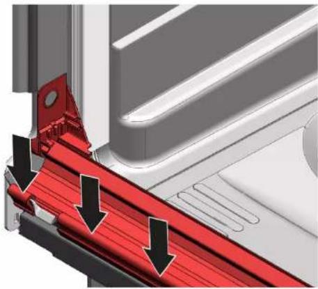
  2. Press the front of the worktop downwards until both catch levers click audibly into place (3).
  3. Screw in the two screws again (4) (optional).

BOSCH SHI4HCS48E - Installing worktop - 2

Repair

4.2 Installing basket system

Prerequisite:

√ The relevant basket has been removed from the appliance.

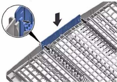
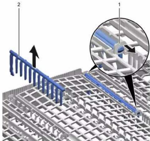
4.2.1 Installing a tab slide for the 86 cm model

Required tools:

Tabguide [00614935]

Cup support clip [00618565]

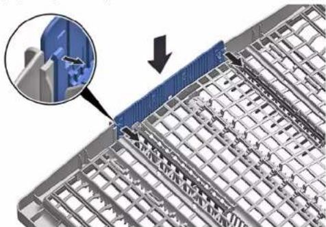
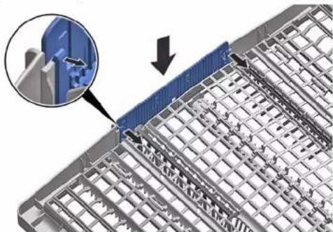
  1. Insert the tab slide diagonally at the front of the basket.

  2. Centre and click the tab chute into place.

4.2.2 Installing cup support clip

Required tools:

Tabguide [00614935]
Cup support clip [00618565]

BOSCH SHI4HCS48E - Installing cup support clip - 1

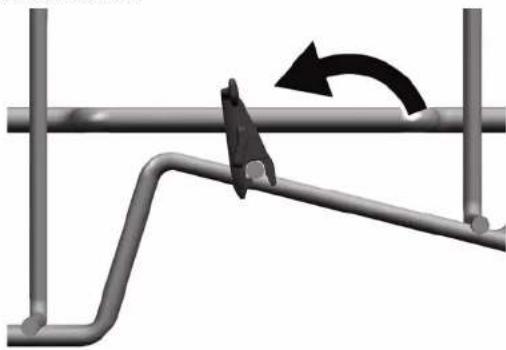
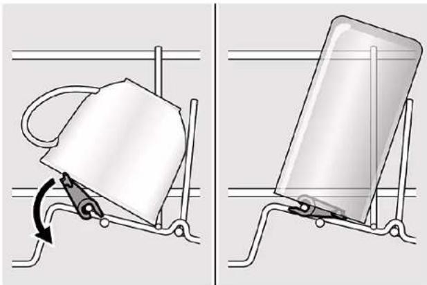
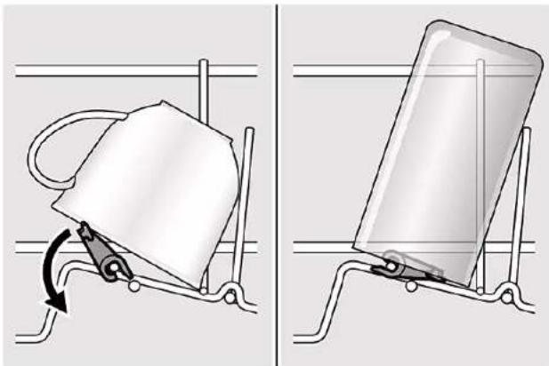
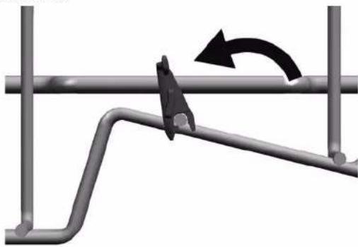
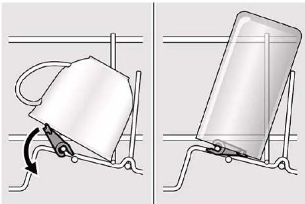
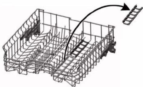
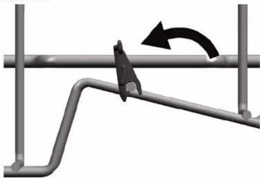
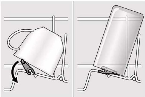
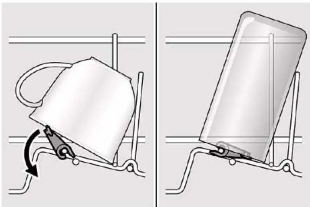
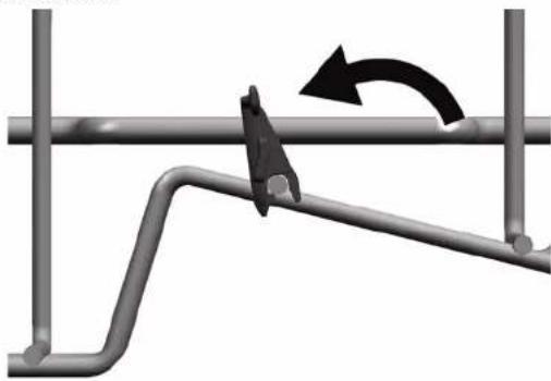
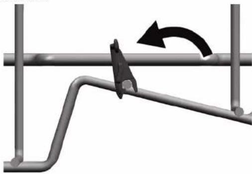
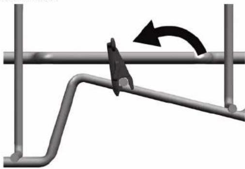
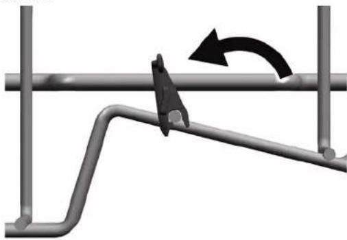
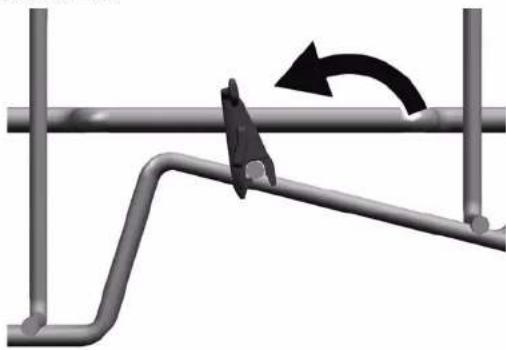
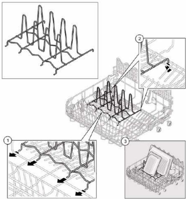
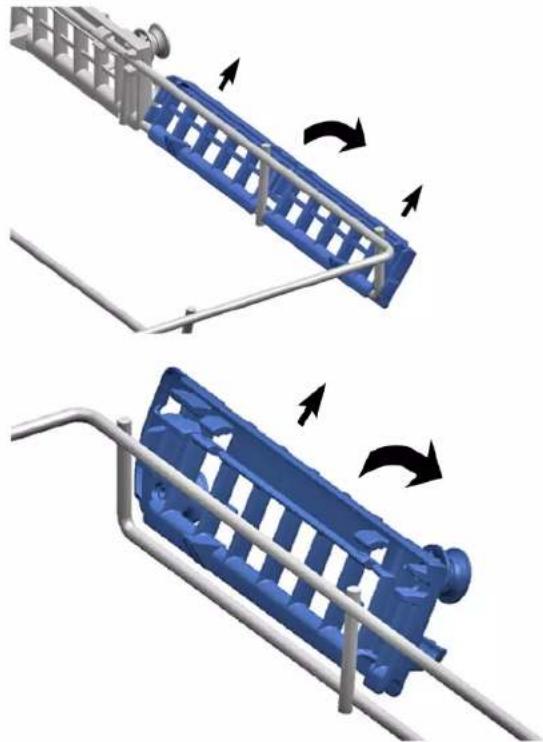
When washing cups, the cup support clip can be folded up. The additional angle reduces the collection of water on the bottom of cups. In the case of tall glasses we recommended leaving the cup support clip folded down. If upper baskets have an optional plastic insert, they must first be removed.

  1. Remove the plastic insert.

Isometric line drawing of a mechanical structure with ladder-like elements and an arrow indicating motion (no text or symbols)

  1. Click the cup support clip into place.
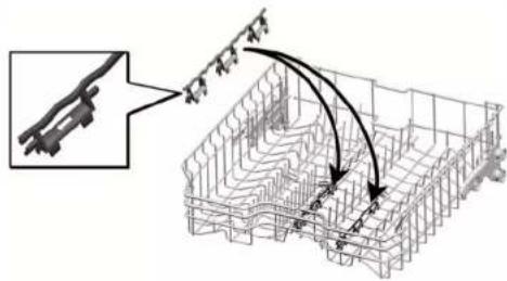
Technical diagram showing structural assembly with labeled components and directional arrows indicating motion or force vectors

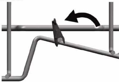
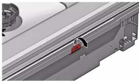
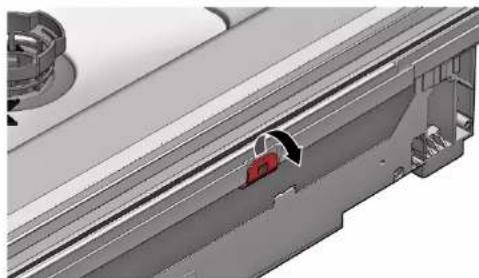
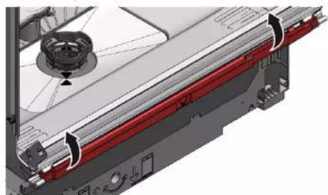
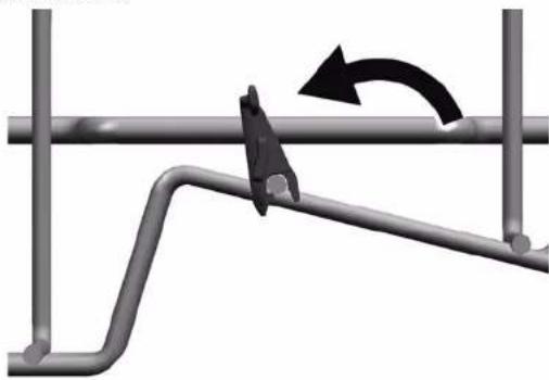
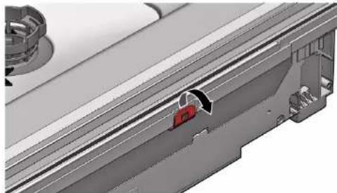
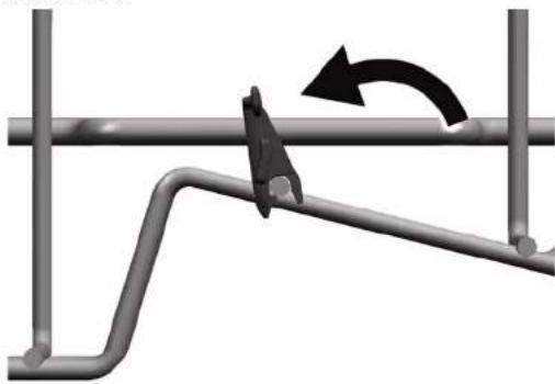
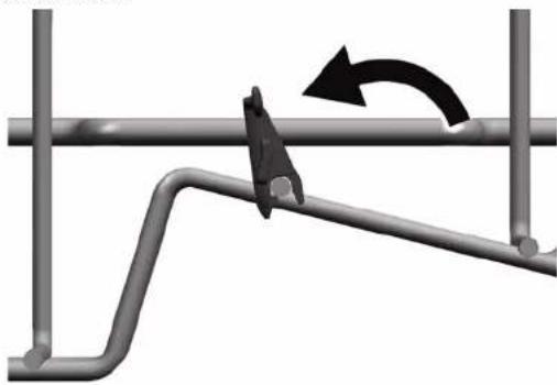
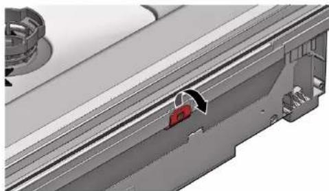
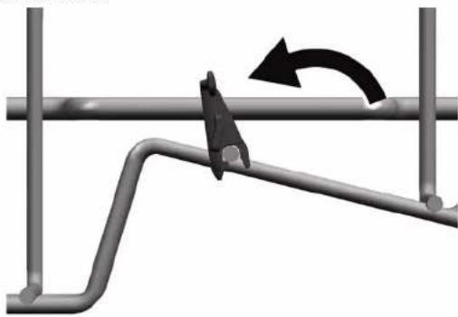
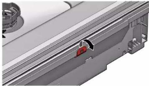
  1. Fold up the clip.

Mechanical diagram showing a lever mechanism with a curved arrow indicating rotational motion (no text or symbols present)

  1. Position the items to be washed.

Two diagrams showing a mechanical device being lifted by a spring, with no visible text or symbols.

4.2.3 Installing steamer insert Required tools:

Tabguide [00614935]
Cup support clip [00618565]

▶ Wedge the steamer insert with the end pieces under the basket system.
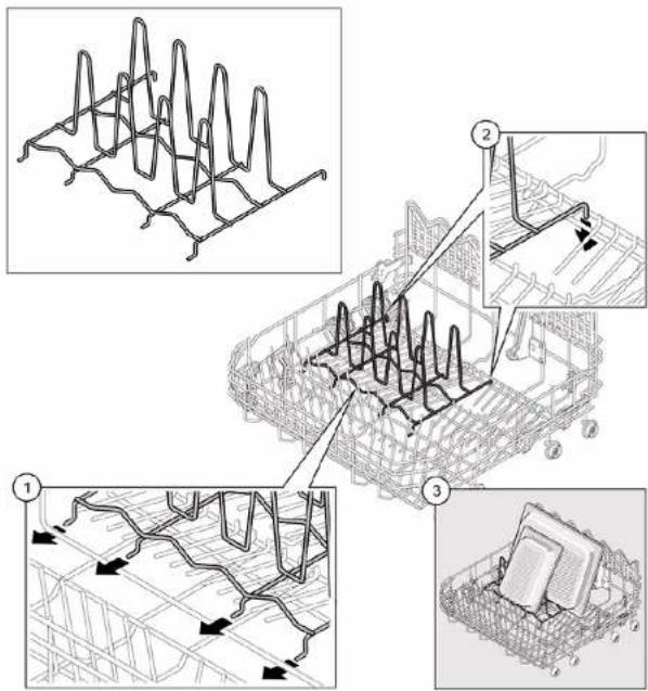
Technical diagram illustrating a multi-step installation or installation process with labeled steps and component illustrations.

BOSCH SHI4HCS48E - Installing steamer insert Required tools: - 2

Repair

4.3 Replacing varioDrawer

4.3.1 Removing varioDrawer

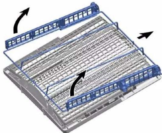
  1. Bend the handle flaps inwards.

3D structural diagram of a metal grid framework with an inset showing a blue door opening (no text or symbols)

  1. Remove the handle upwards.

  2. Press plastic side inserts outwards and press them upwards out of the frame.
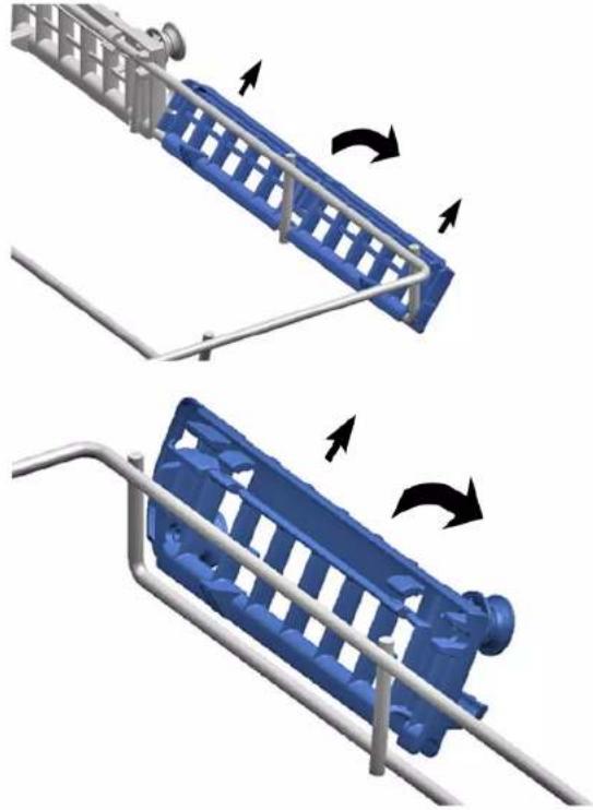
Two blue industrial lockers with metal railings and directional arrows indicating motion (no text or symbols)

BOSCH SHI4HCS48E - Removing varioDrawer - 3

Repair

  1. Carefully bend the guide tabs outwards.
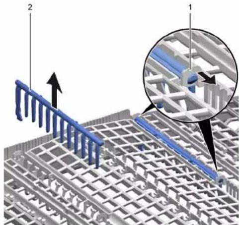
3D architectural diagram showing structural grid and rebar layout with labeled components (no text or symbols present)

  1. Pull the folding spines out of the tabs.

  2. Press metal frame at the front out of the holders.
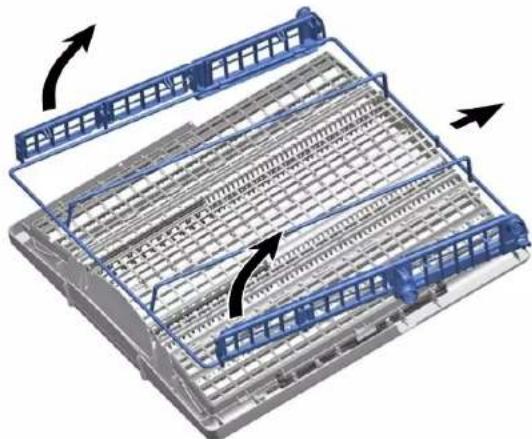
3D diagram of a mechanical assembly with blue structural elements and directional arrows indicating motion (no text or symbols)

  1. Push metal frame back out of the guide.

4.3.2 Installing varioDrawer

▶ Install in reverse order.

Repair

4.4 Replacing spray arms

4.4.1 Removing spray arm

  1. Unscrew the upper spray arm (1) and pull down to remove (2).

Diagram showing a blue propeller with two directional arrows labeled ① and ②, indicating motion or rotation.

  1. Pull down the lower spray arm to remove.
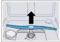
Diagram of a blue propeller inside a vehicle cabin with an upward arrow indicating motion (no text or symbols)

4.4.2 Installing spray arm

  1. Insert the lower spray arm.
    The spray arm clicks into position.
  2. Insert the upper spray arm and screw it firmly in place.

Repair

4.5 Replacing filters

4.5.1 Removing filter

  1. Turn the coarse filter anticlockwise (1) and remove the filter system (2).
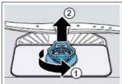
Diagram showing a mechanical component with labeled parts ① and ②, likely illustrating a gear or cam mechanism.

Check that no foreign objects fall into the sump.

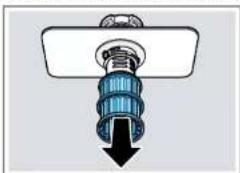
  1. Pull down the micro filter to remove.

Diagram of a mechanical component with a blue spiral and black downward arrow (no text or symbols)

4.5.2 Installing filters

  1. Re-assemble the filter system.
    Make sure that the locking catches on the coarse filter click into position.
  2. Insert the filter system into the appliance and turn the coarse filter clockwise.
    Make sure that the arrow markings match up.

BOSCH SHI4HCS48E - Installing filters - 1

Repair

4.6 Installing baking sheet spray head

  1. Remove top basket.
  2. Insert the baking sheet spray head in the holder (1) and turn to the right (2).
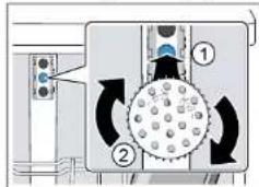
Diagram showing a mechanical or fluid system with labeled components and directional arrows indicating flow or movement.

The baking sheet spray head clicks into position.

BOSCH SHI4HCS48E - Installing baking sheet spray head - 2

Repair

4.7 Replacing power cord

Prerequisite:

√ Appliance is disconnected from power supply.
√ Appliance is disconnected from water supply.
√ Appliances is freely accessible.

4.7.1 Unplugging power cord

- Move the plug of the power cord carefully up and down and pull it out of the mains socket.
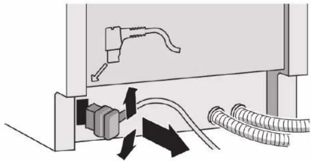
Diagram showing cable routing and connector connections (no text or symbols)

4.7.2 Plugging in power cord

BOSCH SHI4HCS48E - Plugging in power cord - 1

Notice

Overheating of main connection!

Risk of fire

▶ Firmly insert the power cord until it clicks.

- Insert the plug of the power cord into the mains socket until the plug clicks audibly into place.
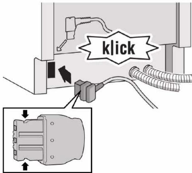
klick

BOSCH SHI4HCS48E - Notice - 2

Repair

4.8 Replacing detergent cover

BOSCH SHI4HCS48E - Replacing detergent cover - 1

A small screwdriver can be used as a levering tool.

Prerequisite:

√ Appliance is disconnected from power supply.
√ Appliance is disconnected from water supply.
√ Door has been opened.
√ Detergent cover has been opened.

4.8.1 Removing detergent cover

  1. Slide the detergent cover in 5 mm.
  2. Lever the detergent cover on the lower side out of the guide rails and take the detergent cover on the upper side out of the guide rails.
  3. Remove the spring.

4.8.2 Inserting spring

  1. Insert the long end of the spring into the mounting hole of the dispenser device (1).
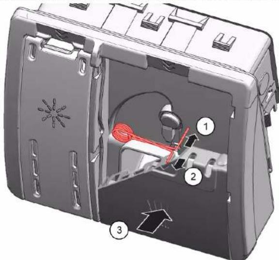
Technical diagram of a device interior with numbered components and directional arrows indicating motion or flow.

  1. Insert the short end of the spring into the mounting hole of the detergent cover (2).
  2. Press cover into the dispenser device (3).

4.8.3 Installing detergent cover

  1. Insert the detergent cover 5 mm before the completely open position into the guide rails on one side. Applying gentle force, press the opposite side into the guide rails.
  2. Check the function of the detergent cover.

BOSCH SHI4HCS48E - Installing detergent cover - 1

Repair

4.9 Replacing wastewater pump cover

Prerequisite:

√ Basket has been removed.
√ Filters has been removed.→ Page 220

4.9.1 Removing wastewater pump cover

  1. Scoop out any water.
    Use a sponge if necessary.
  2. Prise off the pump cover using a spoon and grip it by the crosspiece.
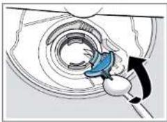
Illustration of a hand using a tool to adjust or install a mechanical component (no text or symbols visible)

  1. Lift the pump cover inwards at an angle and remove.

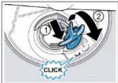
4.9.2 Installing wastewater pump cover

- Insert the pump cover (1) and press down (2).
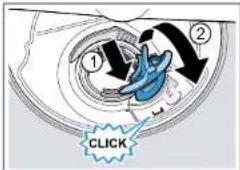
① ② CLICK

The pump cover clicks into position.

BOSCH SHI4HCS48E - Installing wastewater pump cover - 2

Repair

4.10 Replacing side panel

Prerequisite:

√ Appliance is disconnected from power supply.
√ Appliance is disconnected from water supply.
√ Appliances is freely accessible.
√ Free-standing appliances: Worktop has been removed.→ Page 214

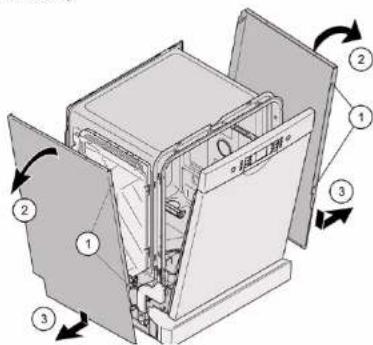
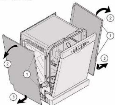
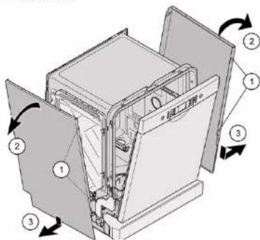
4.10.1 Removing side panel

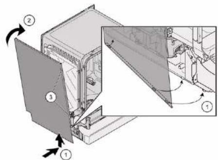
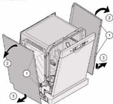
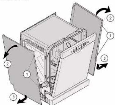
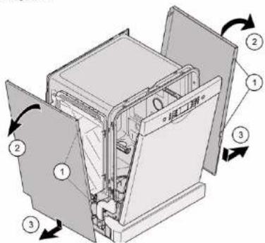
  1. Remove screws from the side panel (1).
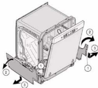
Technical diagram of a multi-chamber refrigerator with numbered parts and directional arrows indicating internal components.

Fig. 1: Fully integrated
Technical diagram of a refrigerator interior with numbered components and directional arrows indicating rotation or movement.

  1. Tilt the side panel slightly outwards at the top (2).
  2. Lower the side panel and pull it out of the base trough (3).

BOSCH SHI4HCS48E - Removing side panel - 3

Repair

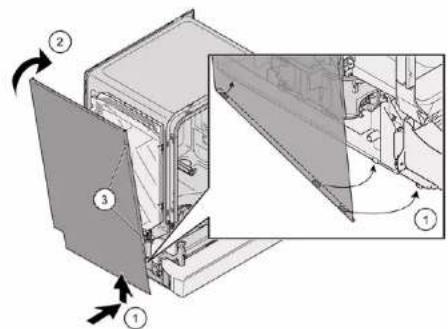
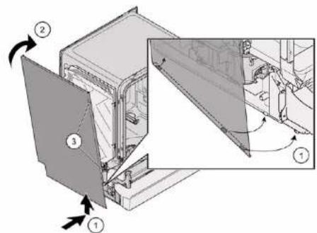
4.10.2 Installing side panel

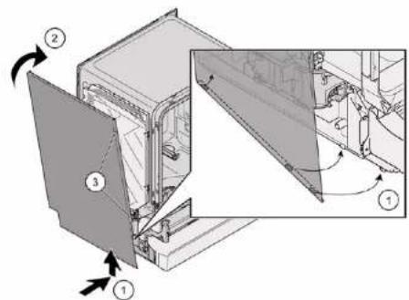
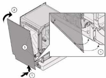
  1. Insert the side panel into the base trough (1).
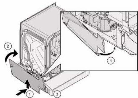
Technical diagram showing a mechanical assembly with numbered components and directional arrows indicating motion or assembly steps.

Fig. 2: Fully integrated
Technical diagram showing a device's internal structure with numbered annotations and directional arrows indicating assembly or movement.

  1. Press the side panel onto the appliance (2).
  2. Secure the side panel with screws (3).

BOSCH SHI4HCS48E - Installing side panel - 3

Repair

4.11 Replacing outer door

Prerequisite:

√ Appliance is disconnected from power supply.
√ Appliance is disconnected from water supply.

Just remove the screws which are described in the following steps.

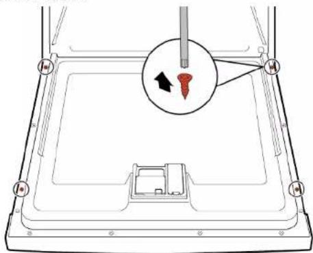
  1. Open door.
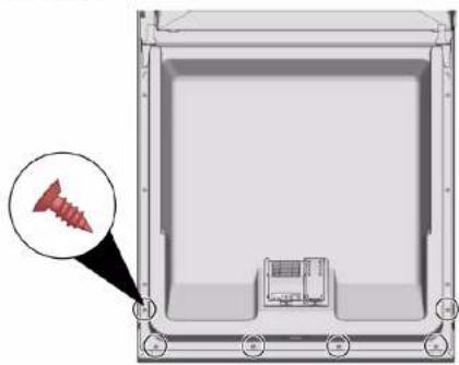
  2. Remove four screws.

Diagram of a device with a screwdriver inserted into a tray, showing a close-up of the tray area (no text or symbols present)

3.

BOSCH SHI4HCS48E - Replacing outer door - 2

Secure the door by holding it on one side.

Remove two screws.
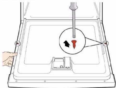
Diagram showing a hand inserting a screw into a device with a magnified view of the screw and its insertion direction.

BOSCH SHI4HCS48E - Replacing outer door - 4

Repair

Prerequisite:

√ Insulating fleece has been correctly positioned and fixed on the inside of the outer door.

√ Hinges are inserted into the outer door.

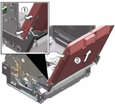
  1. Close the inner door without snapping it shut.

  2. Push the outer door upwards underneath the control panel (1).
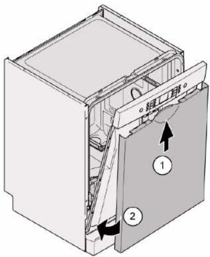
Technical diagram of a refrigerator interior with labeled components and directional arrows indicating parts of the door.

  1. Press the outer door against the inner door and hold (2).

4.

BOSCH SHI4HCS48E - Prerequisite: - 2

Secure the door by holding it on one side.

Open the door and secure it with two screws (4 x 11 mm metal screws).
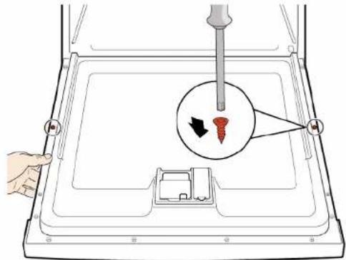
Diagram showing a hand holding a screwdriver inserted into a tray with a magnified inset highlighting the screw and its direction.

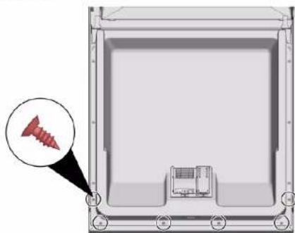
  1. Secure the outer door with four screws (4 x 11 mm metal screws).
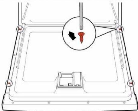
Diagram of a device with a screw and a magnified inset showing the screw being inserted (no text or symbols present)

BOSCH SHI4HCS48E - Prerequisite: - 5

Repair

4.12 Replacing control panel

BOSCH SHI4HCS48E - Replacing control panel - 1

If an operating module is defective, the entire control panel must be replaced.

Prerequisite:

√ Appliance is disconnected from power supply.
√ Appliance is disconnected from water supply.
√ Outer door has been removed.
√ Outer door has been removed (fully integrated/integrated).

4.12.1 Removing control panel

  1. Disconnect electrical connections from the control panel and the low rinse-aid sensor (1, 2).
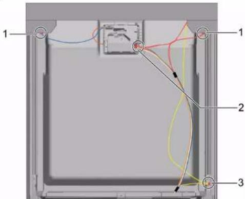
Technical diagram of a device interior with numbered components and colored wiring, likely illustrating a mechanical or electrical assembly.

  1. Disconnect the earth cable (3) (optional).
  2. Open the appliance door.
  3. Secure the control panel to prevent it from falling down (hold on to it).

  4. Remove six screws.

Diagram of a device interior with screw and control panel, no text or symbols present

  1. Remove the control panel.

4.12.2 Installing control panel

BOSCH SHI4HCS48E - Installing control panel - 1

Use screws 4 x 16 mm.

▶ Install in reverse order.

BOSCH SHI4HCS48E - Installing control panel - 2

Repair

  1. Remove cord guide cover out.

Mechanical assembly diagram showing a red component with a numbered arrow pointing to a specific part (no text or symbols present)

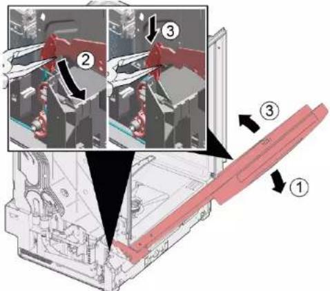
    1. Open door slightly (1).
  1. Fix in the groove of the base trough (2).

  2. Slowly close the door (3).

Technical diagram showing assembly steps of a mechanical component with numbered annotations indicating different states or features.

The cord system attaches itself automatically to the door hinge.

BOSCH SHI4HCS48E - Repair - 3

Repair

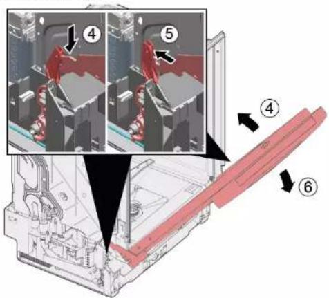
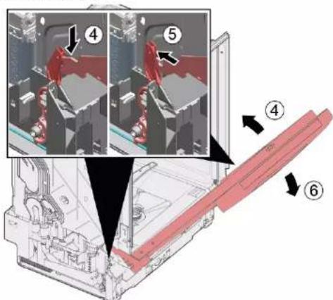
    1. Slightly close the door (4).
  1. Move the groove to the back and release the door hinge (5).

  2. Open the door (6).

Technical diagram showing assembly steps of a mechanical component with numbered annotations indicating different states or features.

  1. Repeat the process again on other side of appliance.

BOSCH SHI4HCS48E - Repair - 2

Repair

4.14 Replacing toe panel

BOSCH SHI4HCS48E - Replacing toe panel - 1

The feet are identical and can be swapped over.

Prerequisite:

√ Appliance is disconnected from power supply.
√ Appliance is disconnected from water supply.
√ Outer door has been removed.
√ Outer door has been removed (fully integrated/integrated).

4.14.1 Removing toe panel

1.

BOSCH SHI4HCS48E - Removing toe panel - 1

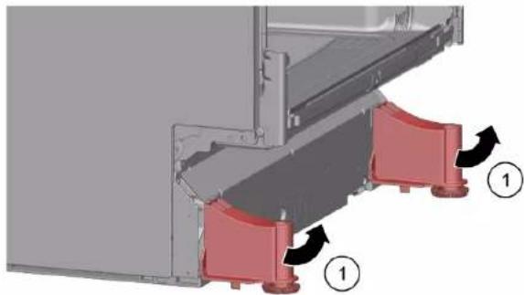
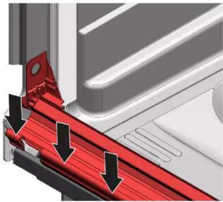
Incorrect removal. If the toe panel is loosened at the side and removed, the two brackets may break away. If only one bracket is damaged, the side can be changed as the brackets are identical. It is advisable to place something under the appliance at the front on the side to relieve the load on the toe panel with the feet.

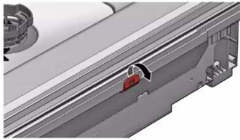
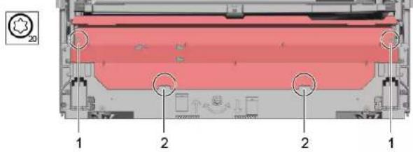
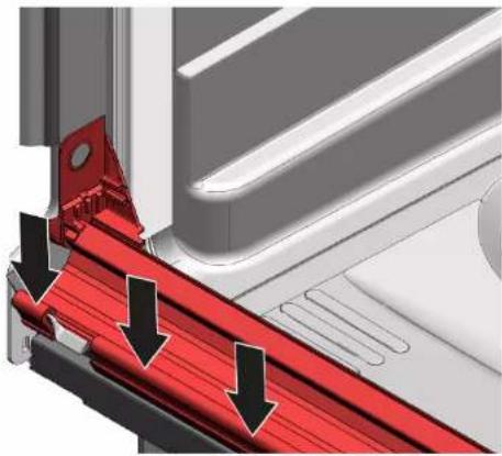
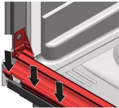
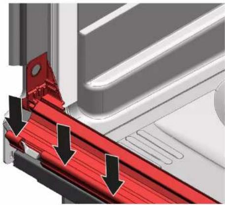
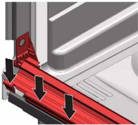
  1. Reach into the guides (1) with a screwdriver and release the catch by pushing downwards.
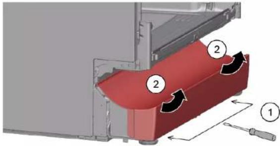
Technical diagram showing a red mechanical component with numbered parts and directional arrows indicating motion or flow.

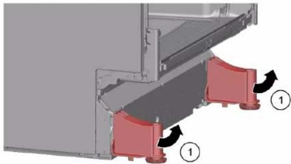
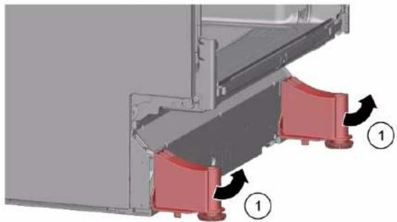
  1. Lift the panel off.

  2. Remove the feet forwards (1).

Mechanical assembly diagram showing red clamps mounted on a metal frame, with numbered callouts indicating components (no text or symbols present)

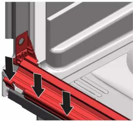
4.14.2 Installing toe panel

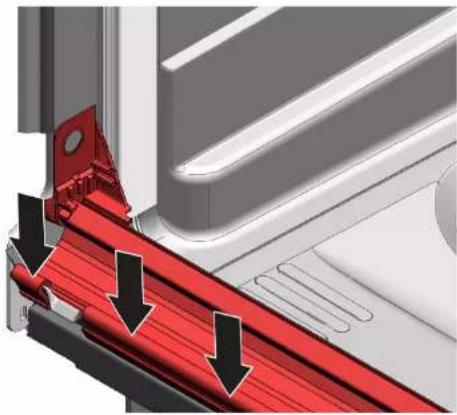
  1. Insert the feet.
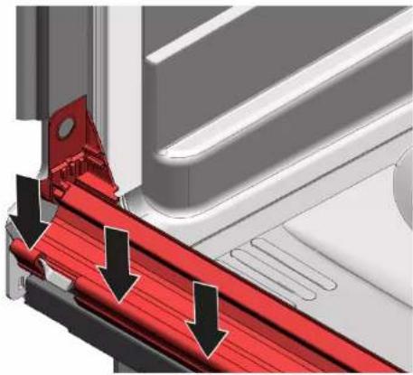
  2. Attach the toe panel at the top (1) and press it down until it audibly clicks into place (2).
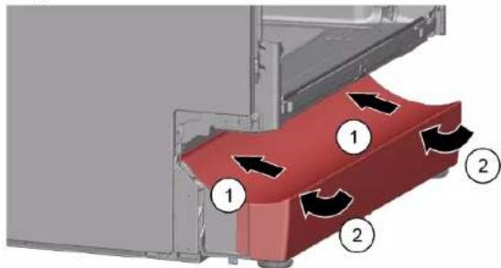
Technical diagram showing a red component with numbered arrows indicating flow or movement, likely illustrating a mechanical or fluid system.

BOSCH SHI4HCS48E - Installing toe panel - 2

Repair

4.15 Replacing base socket plate

BOSCH SHI4HCS48E - Replacing base socket plate - 1

The base socket plate is located in the lower area at the front.

Prerequisite:

√ Appliance is disconnected from power supply. √ Appliance is disconnected from water supply.
√ Furniture panel (optional) has been removed.
√ Outer door has been removed.
√ Outer door has been removed (fully integrated/integrated).
√ Toe panel has been removed (optional).→ Page 232

4.15.1 Removing base socket plate

  1. Remove two screws (1).

1 2 2 1

  1. Disengage catch elements (2).

  2. Tilt the base socket plate carefully forwards (1).
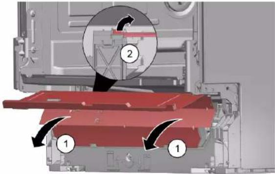
Technical diagram showing a mechanical assembly with numbered components and directional arrows indicating motion or flow.

4.

BOSCH SHI4HCS48E - Removing base socket plate - 3

Depending on the model series, the plug to the EmotionLight is still secured to the base.

Unlock the plug on the catch tappet and pull to the rear (optional) (2).

4.15.2 Installing base socket plate

▶ Install the base socket plate in reverse order.

BOSCH SHI4HCS48E - Installing base socket plate - 1

Repair

4.16 Replacing overflow conduit

BOSCH SHI4HCS48E - Replacing overflow conduit - 1

The overflow conduit is located in the front lower area of the appliance.

Prerequisite:

√ Appliance is disconnected from power supply.
√ Appliance is disconnected from water supply.
√ Furniture panel has been removed (optional).
√ Outer door has been removed.
√ Toe panel has been removed (optional).→ Page 232
√ Base socket plate has been removed.→ Page 233

4.16.1 Removing overflow channel

BOSCH SHI4HCS48E - Removing overflow channel - 1

Residual water

■ When the drainage hose is removed, residual water may run out.

- Catch water or remove from the base pan with suction syringe.

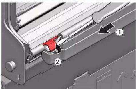
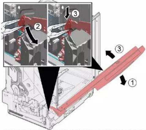
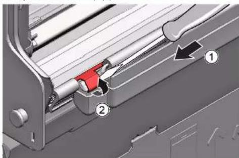
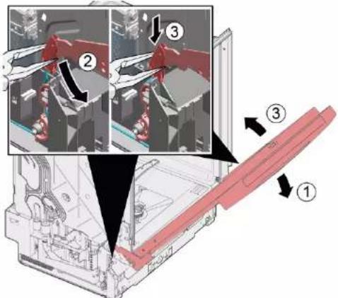
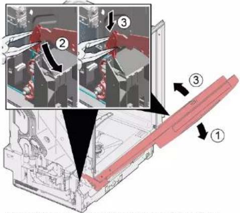
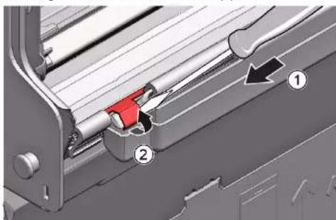
  1. Lever out of the catch mechanism at the top (1, 2).
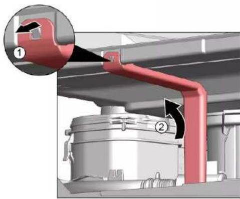
Mechanical assembly diagram showing a red lever mechanism with labeled parts (1 and 2), no readable text or symbols present.

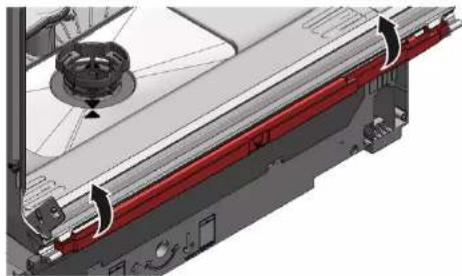
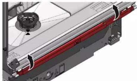
  1. Release catch element at top.

3D mechanical assembly diagram showing a component with a red arrow indicating direction (no text or symbols)

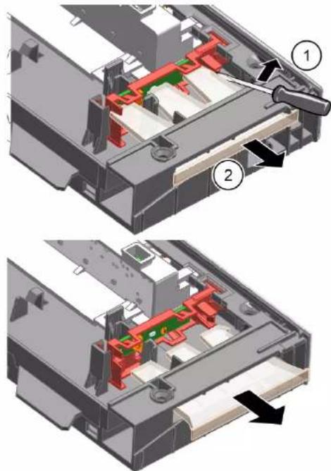
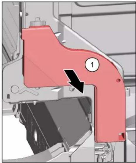
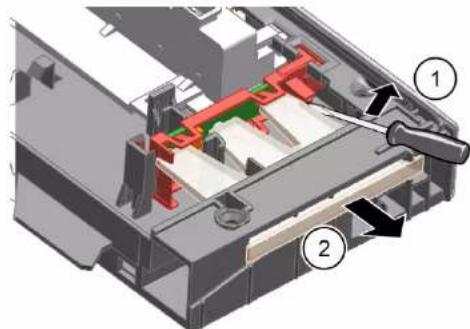
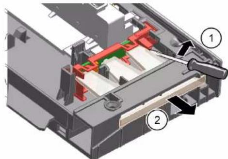
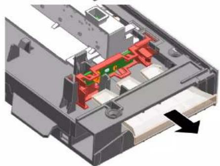
    1. Insert screwdriver below metal brake (1).
  1. Gently release metal clip (2).

Mechanical assembly diagram showing a lever mechanism with labeled parts (1 and 2), no readable text or symbols present.

BOSCH SHI4HCS48E - Removing overflow channel - 5

Repair

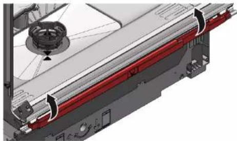
  1. Lift overflow conduit off.

3D mechanical assembly diagram showing internal components and mounting features (no text or symbols visible)

4.16.2 Installing overflow conduit

BOSCH SHI4HCS48E - Installing overflow conduit - 1

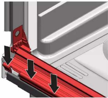
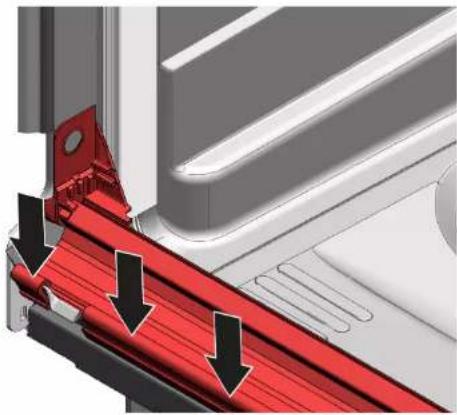
Water damage due to incorrect installation of the overflow conduit! Correctly insert the overflow conduit at the bottom into the guide of the base trough. Click the overflow conduit correctly into place at the top.

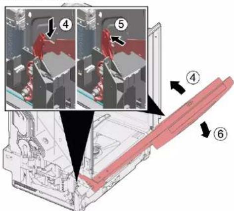
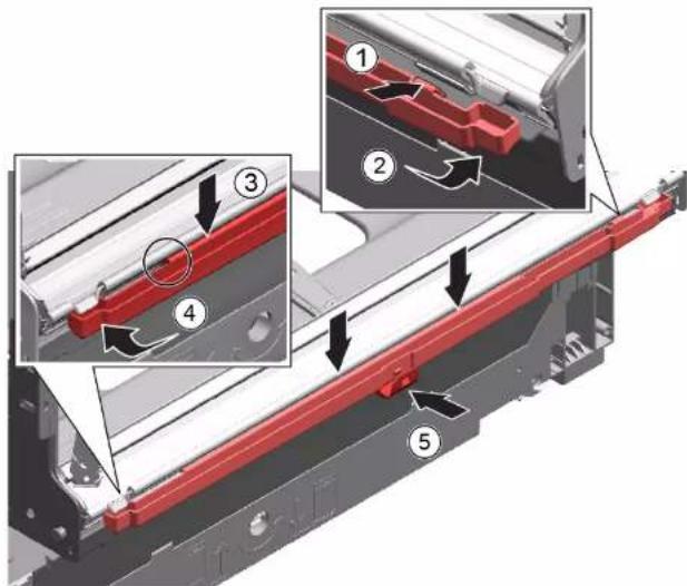
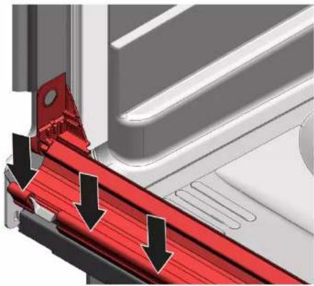
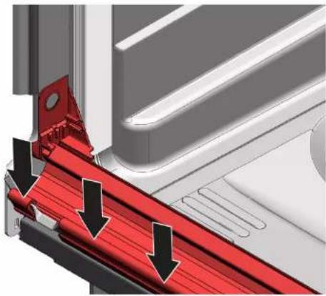
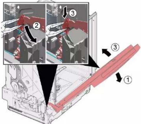
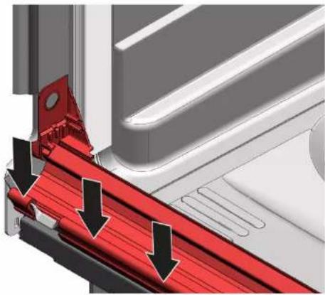
    1. Place overflow conduit (1).
  1. Move overflow conduit into seal (2).

  2. Press overflow conduit in guide of seal (3).
  3. Insert overflow conduit concisely (4).
  4. Clip in overflow conduit (5).

Technical diagram showing mechanical assembly with numbered components and directional arrows indicating motion or flow

BOSCH SHI4HCS48E - Installing overflow conduit - 3

Repair

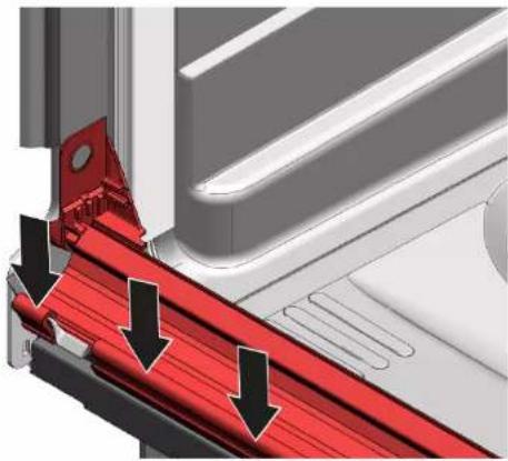
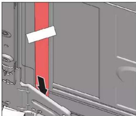
  1. Check installation left and right. 3. Check firm seat.
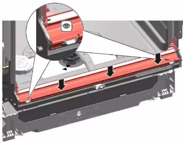
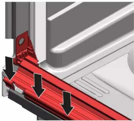
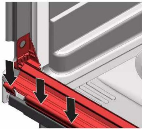
Mechanical assembly diagram showing a red component with arrows indicating motion or assembly, no visible text or symbols

3D diagram of a vehicle door with red and black arrows indicating airflow or movement (no text or symbols)

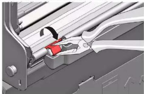
  1. Clip in metal clip on left and right side.
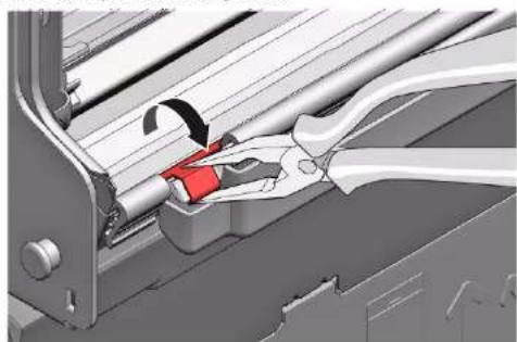
Mechanical assembly diagram showing a clamping tool interacting with a mechanical component (no text or symbols visible)

BOSCH SHI4HCS48E - Repair - 4

Repair

4.17 Replacing inner door

Prerequisite:

√ Appliance is disconnected from power supply.
√ Appliance is disconnected from water supply.

  1. Secure door hinge with screws.
  2. Place inner door on door hinge.
  3. Secure inner door with screws.

4.17.1 Removing inner door

  1. Remove screws (1).
  2. Remove inner door upwards (2).

Mechanical assembly diagram showing two views of a red component with arrows indicating parts of the opening (no text or symbols present)

4.17.2 Installing inner door

  1. Flap door seal to front.
  2. Move inner door behind door seal.
  3. Close inner door.
  4. Flap door seal upwards. Sideparts show upwards.
  5. Move door hinge upwards.

Repair

4.18 Replacing door hinge

Prerequisite:

√ Appliance is disconnected from power supply.
√ Appliance is disconnected from water supply.
√ Appliances is freely accessible.
√ Side panel has been removed.→ Page 225
√ Outer door has been removed.
√ Inner door has been removed.
√ Control panel has been removed.→ Page 229
√ Door spings has been fixed. → Page 230
√ Toe panel has been removed.→ Page 232
√ Base socket plate has been removed.→ Page 233
√ Overflow channel has been removed.→ Page 234

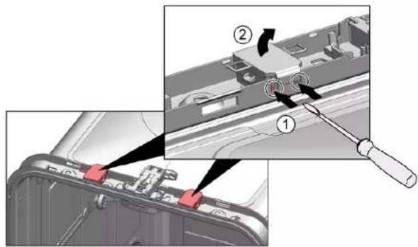
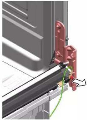
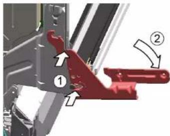
    1. Release catch hook with a screwdriver(1).
  1. Pull door hinge forwards (2).

Mechanical assembly diagram showing two labeled parts (① and ②) with directional arrows indicating movement or force (no text or symbols beyond labels)

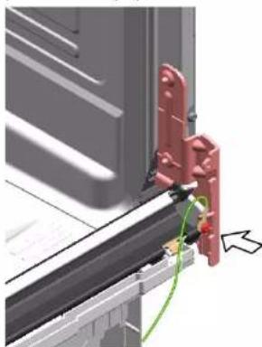
  1. Release ground connection on door hinge.
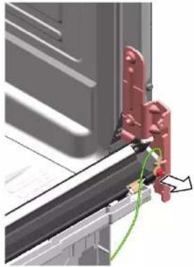
Mechanical assembly diagram showing a red bracket mounted on a metal frame with a green cable and arrow indicating connection (no text or symbols present)

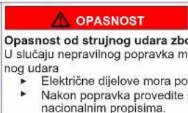
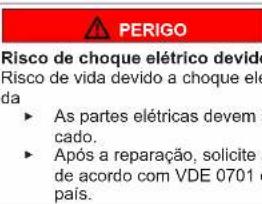
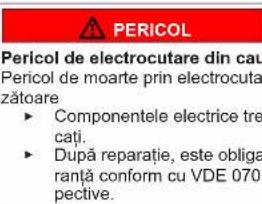
Risk of electric shock due to live parts!

Danger to life through electric shock in case of improper repair

▶ Electric parts should be repaired by a qualified electricians.
▶ After the repair have a safety test according VDE 0701 or country-specific regulations performed.

BOSCH SHI4HCS48E - Prerequisite: - 3

Repair

    1. Place hinge on appliance (1).
  1. Move hinge downwards (2) till it is latched to the appliance.
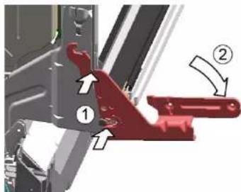
Technical diagram showing mechanical assembly with numbered components and directional arrows indicating motion or movement.

2.

BOSCH SHI4HCS48E - Repair - 2

A missing ground connection can lead to mains potential on door.

Establish ground connection.
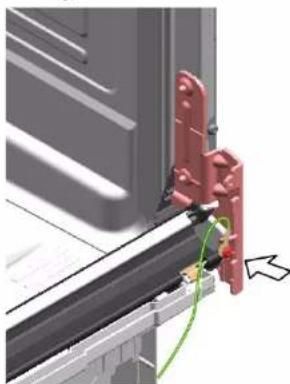
3D mechanical assembly diagram showing red bracket and green cable connection (no text or symbols)

BOSCH SHI4HCS48E - Repair - 4

Repair

4.19 Replacing (lower) door seal

Prerequisite:

√ Appliance is disconnected from power supply.
√ Appliance is disconnected from water supply.
√ Outer door has been removed.
√ Base socket plate has been removed.→ Page 233
√ Toe panel has been removed (optional).→ Page 232
√ Door springs have been removed.
√ Control panel has been removed.
√ Cable harness holder on bottom right has been removed.

4.19.1 Removing the door seal

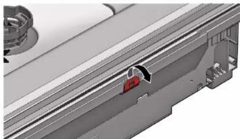
  1. Remove the two retaining clips on the lower door seal (1, 2).
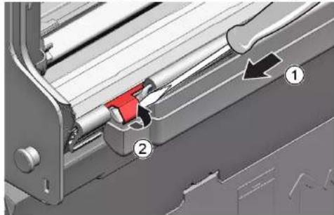
Mechanical assembly diagram showing a lever mechanism with labeled parts (1 and 2), no readable text or symbols present.

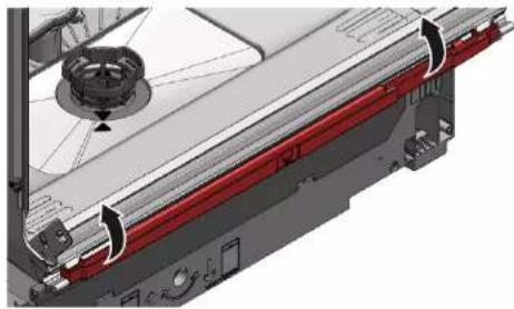
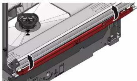
  1. Detach the overflow channel.

3D mechanical assembly diagram showing a sliding mechanism with a red component (no text or symbols visible)

  1. Lift the overflow gutter off.

3D mechanical assembly diagram showing internal components and a central hub (no text or symbols visible)

Repair

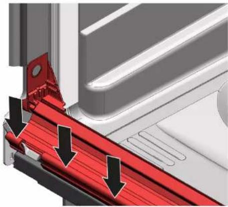
  1. Remove the lower door seal from the inner door.
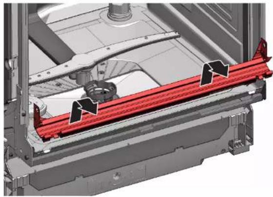
3D mechanical assembly diagram showing a red structural component with arrows indicating flow or movement (no text or symbols present)

4.19.2 Installing the door seal

  1. Fit the sealing caps on the left and right to the sealing rail with the door seal.
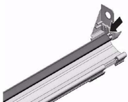
Technical illustration of a mechanical bracket assembly (no text or symbols visible)

  1. Insert the door seal with the sealing flap in the inner door.

  2. Secure the door seal with two retaining clips.

BOSCH SHI4HCS48E - Installing the door seal - 2

Repair

4.20 Replacing (upper) door seal

Prerequisite:

√ Appliance is disconnected from power supply.
√ Appliance is disconnected from water supply.

4.20.1 Removing door seal

Remove door seal from inner frame.

4.20.2 Installing door seal

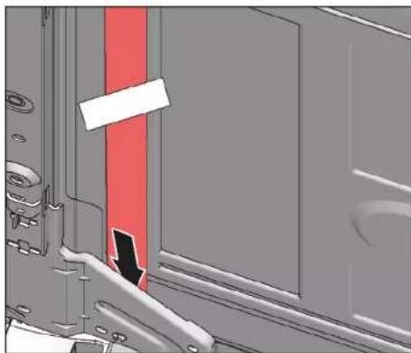
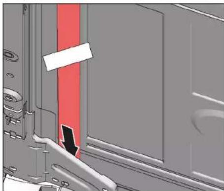
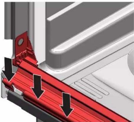
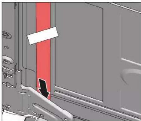
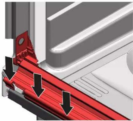
The door seal must be cut to the correct length before installation. This is 1750 mm for appliances of 81 cm in height and 1850 mm for appliances of 86 cm in height.

  1. Prepare appropriate door seal.
  2. Ensure correct installation position of sealing profile.
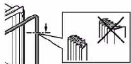
BOSCH SHI4HCS48E - Installing door seal - 1

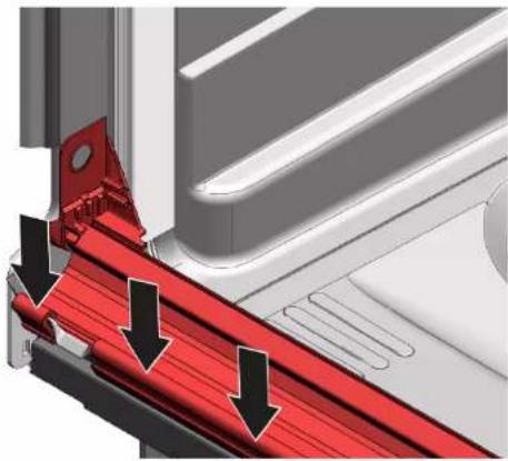
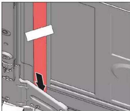
  1. White dot must be on level with sealing bed strip.
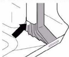
Diagram of a hand holding a tool or grip, with a black arrow pointing to the grip area (no text or symbols present)

4.

BOSCH SHI4HCS48E - Installing door seal - 3

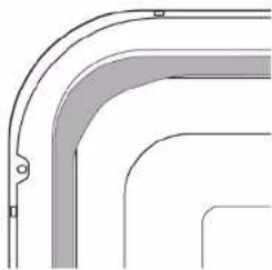
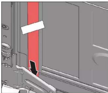
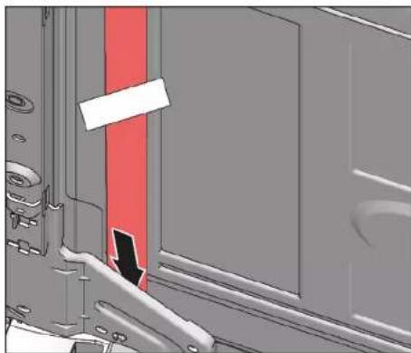
Sealing must not be wavy or stretched at corners. Seal is cut off diagonally at ends and tapers away into bottom of container at front.

Position end of seal straight to front underneath inner door. Seal should lie against side of container as far as possible.

BOSCH SHI4HCS48E - Installing door seal - 4

Correctly installed door seal:

Pure technical line drawing of curved structural elements without any text or symbols

BOSCH SHI4HCS48E - Installing door seal - 6

Repair

4.21 Replacing EmotionLight

BOSCH SHI4HCS48E - Replacing EmotionLight - 1

The EmotionLight is situated in the upper front exterior area of the rinsing tank.

Prerequisite:

√ Appliance is disconnected from power supply.
√ Appliance is disconnected from water supply.
√ Appliances is freely accessible.
√ Worktop has been removed (optional).
The right-hand side panel has been removed (optional).→ Page 225

4.21.1 Removing EmotionLight

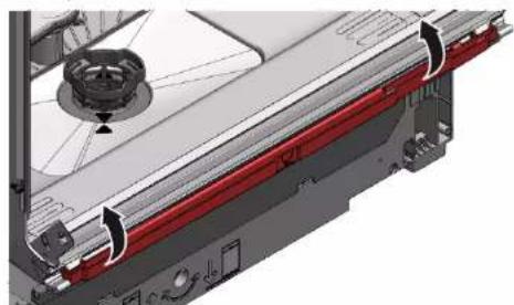
  1. Detach catch hook at the rear (1).

Diagram showing a device's internal components with numbered annotations indicating parts of the main body and parts of the device.

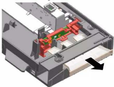
  1. Remove the holder upwards (2).
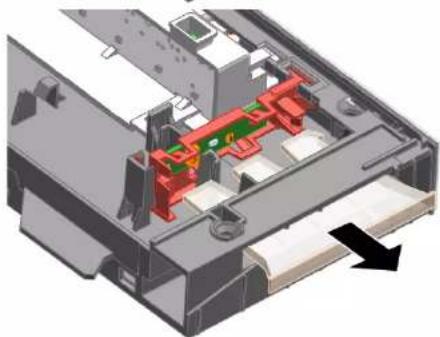
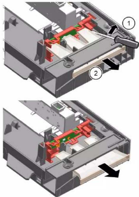
  2. Pull plug out of connector (bottom right at front of appliance).
  1. Remove electrical connection from the power module.
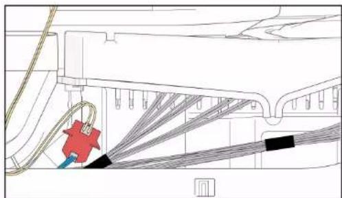
Technical line drawing of a mechanical assembly with wires and components (no text or symbols)

  1. Remove EmotionLight from the appliance.

4.21.2 Installing EmotionLight

  1. Insert the holder into the rinsing tank frame (1).
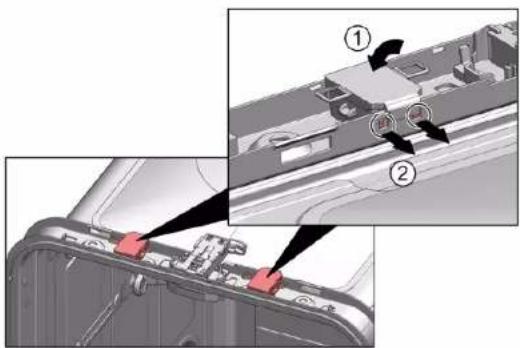
Technical diagram showing a device's internal components with numbered annotations indicating parts of the main body and parts of the chassis.

BOSCH SHI4HCS48E - Installing EmotionLight - 2

Repair

  1. Engage the catch hook (2).

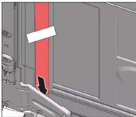
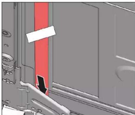
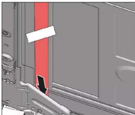
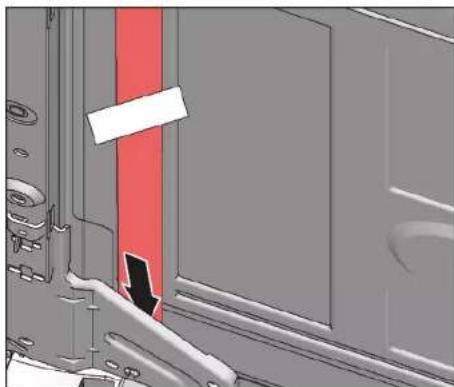
3.

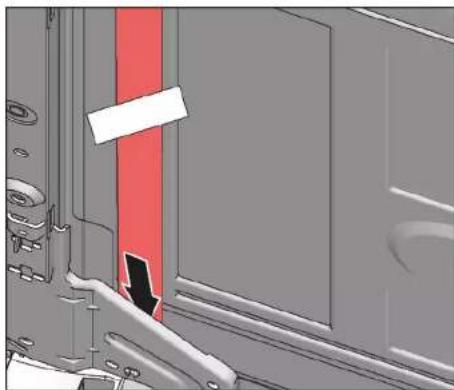
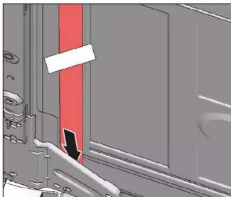
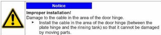
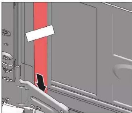
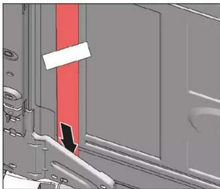
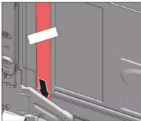
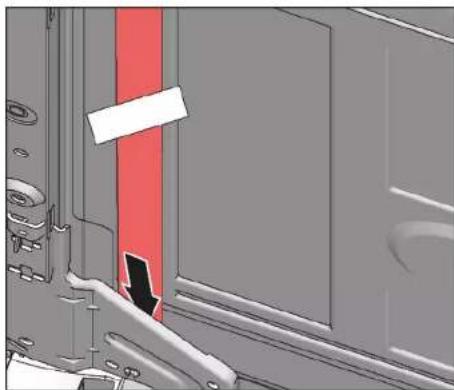
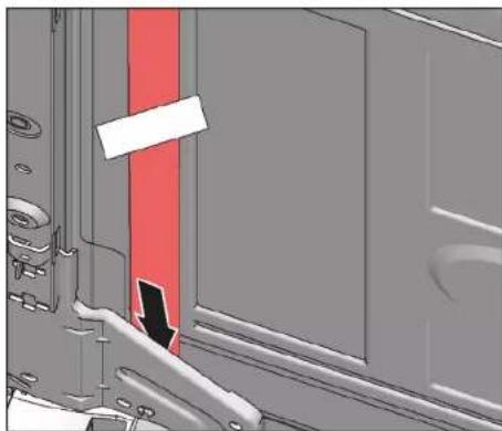
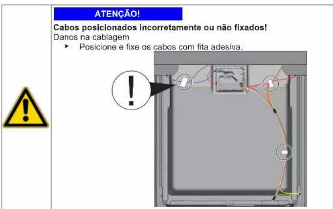
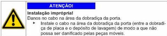
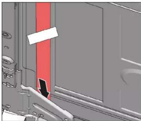
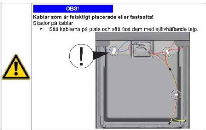
Notice Improper installation! Damage to the cable in the area of the door hinge. ► Install the cable in the area of the door hinge (between the plate hinge and the rinsing tank) so that it cannot be damaged by moving parts.

Install the cable on the right lower side.

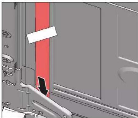
Close-up of a mechanical component with a red vertical line and black arrow pointing to a feature (no visible text or symbols)

BOSCH SHI4HCS48E - Repair - 3

Repair

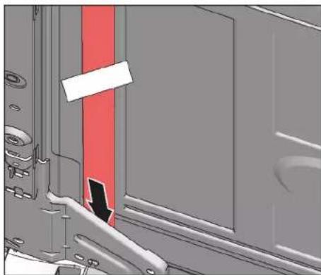
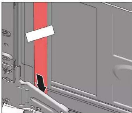
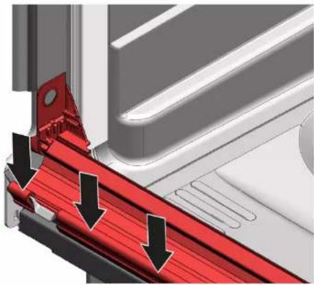
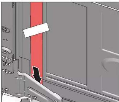
Close-up of a mechanical component with a red vertical stripe and black arrow indicating a cut or section (no text or symbols visible)

Fig. 3: Flat cable

  1. Insert the plug.

BOSCH SHI4HCS48E - Repair - 2

Repair

4.22 Replacing TimeLight

BOSCH SHI4HCS48E - Replacing TimeLight - 1

Replace the TimeLight only as a complete part. The TimeLight module is fixed to the rear of the base socket plate.

Prerequisite:

√ Appliance is disconnected from power supply.
√ Appliance is disconnected from water supply.
√ Toe panel has been removed.→ Page 232
√ Base socket plate has been removed and turned.→ Page 233

4.22.1 Removing TimeLight

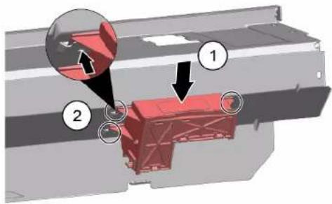
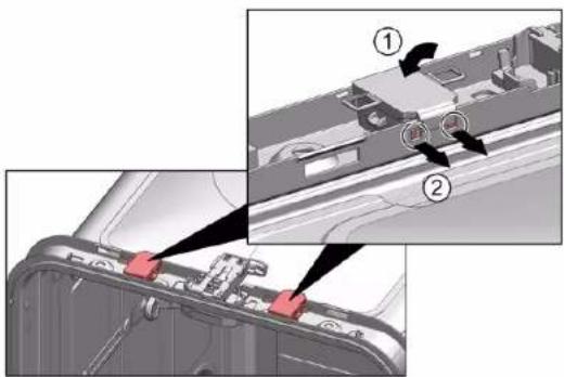
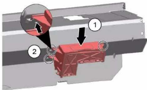
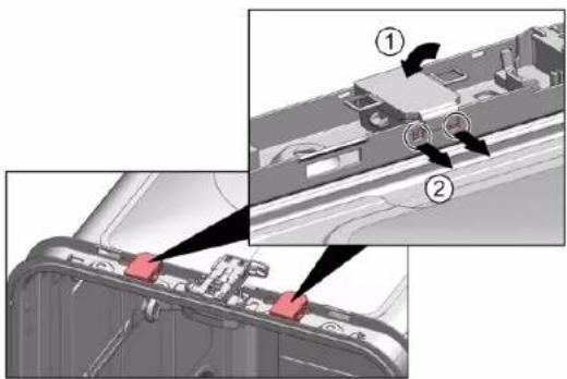
  1. Bend the catch elements (1) slightly outwards.
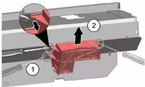
Technical diagram showing a mechanical assembly with numbered components and directional arrows indicating motion or force.

  1. Pull the TimeLight module upwards out of the guide (2).

4.22.2 Installing TimeLight

  1. Bend the catch elements (1) back again.
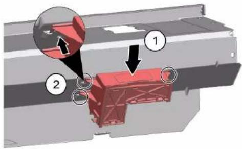
Technical diagram showing a red structural component with numbered annotations indicating parts of the assembly.

  1. Push the TimeLight module into the guide (2).
  2. Connect the electrical connection.

BOSCH SHI4HCS48E - Installing TimeLight - 2

Repair

4.23 Replacing Gap illumination

Prerequisite:

√ Appliance is disconnected from power supply.
√ Appliance is disconnected from water supply.
√ Outer door is disassembled.
√ Operation panel has been removed.

4.23.1 Removing Gap illumination

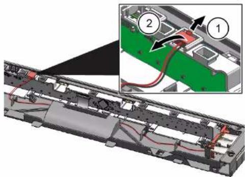
    1. Detach catch (1).
  1. Remove electrical connection from the operation module (2).
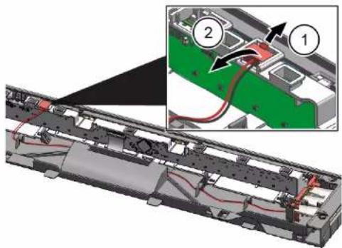
Technical diagram showing a device interior with labeled components and wiring, including numbered annotations 1 and 2.

    1. Detach catch hook at rear (1).
  1. Remove light fibre (2).

3D mechanical assembly diagram showing internal components with numbered callouts (1 and 2), no readable text or symbols present.

3D mechanical assembly diagram showing internal components with no visible text or symbols

BOSCH SHI4HCS48E - Removing Gap illumination - 4

Repair

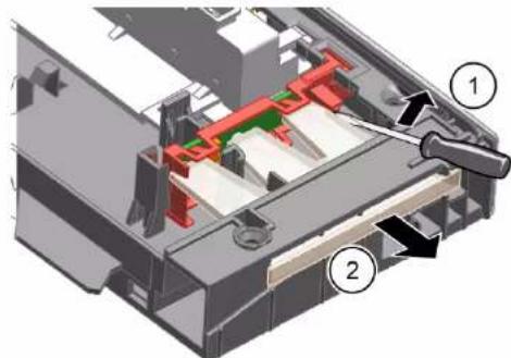
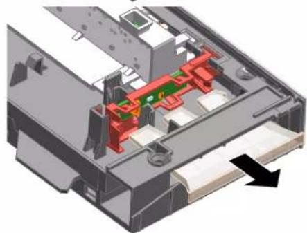
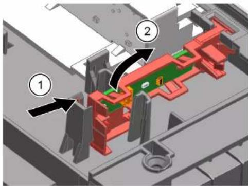
    1. Detach catch hook (1).
  1. Lift up PCB with holder and remove it from operation module frame (2).
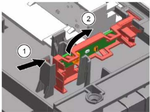
Technical diagram of a mechanical assembly with numbered components, likely illustrating a gear or mounting mechanism.

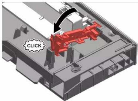
4.23.2 Installing Gap illumination

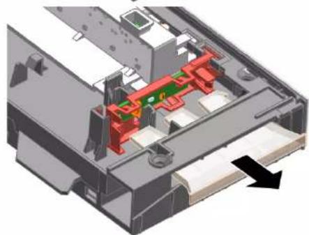
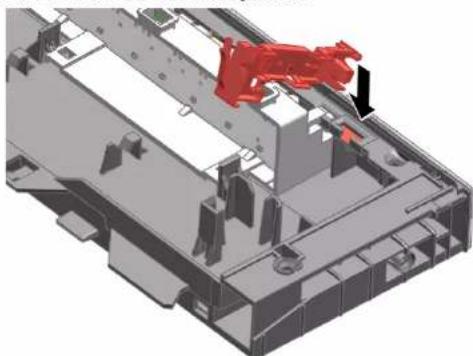
  1. Insert PCB holder to operation module frame.
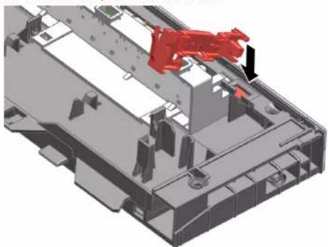
3D mechanical assembly diagram showing a red component inserted into a housing (no text or symbols visible)

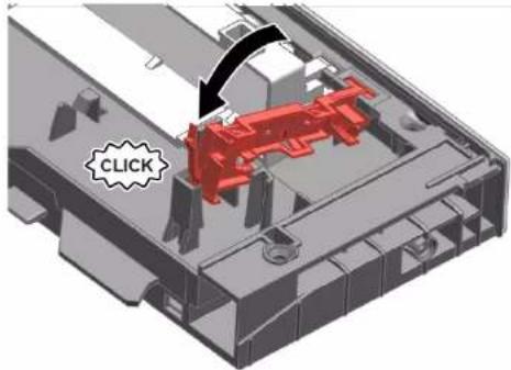
  1. Tighten it with a "click" sound.

CLICK

  1. Install light fibre and tighten it with a "click" sound.
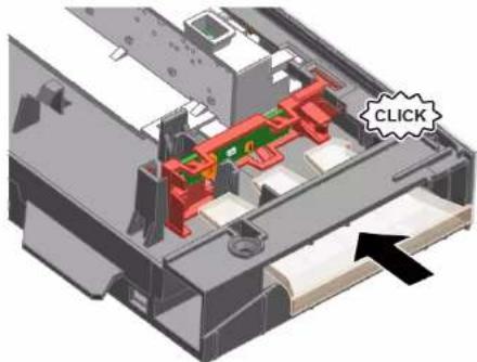
3D mechanical assembly diagram showing internal components with a highlighted 'CLICK' button (no text or symbols beyond the label)

  1. Connect wire to operation module.

Remonditeave - Nõudepesumasin

i Selle dokumendiga seoses 251

1.1 Tähtis teave 251

1.1.1 Eesmärk 251

1.2 Sümbolite selgitus 251

1.2.1 Ohutasemed.... 251

BOSCH SHI4HCS48E - i Selle dokumendiga seoses 251 - 1

Remont

  1. Pange pestavad esemed paika.

Two diagrams showing a mechanical device being lifted by a spring, with no visible text or symbols.

4.2.3 Auruti vahetüki paigaldamine

Eritööriistad:

Tabletisahtli juhik [00614935]
Tassitoe klamber [00618565]

BOSCH SHI4HCS48E - Auruti vahetüki paigaldamine - 1

Remont

4.3 Sahtli varioDrawer vahetamine

4.3.1 Sahtli varioDrawer eemaldamine

BOSCH SHI4HCS48E - Sahtli varioDrawer eemaldamine - 1

Remont

  1. Eemaldamiseks tömmake alumist pihustit alla.
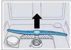
Diagram of a blue propeller inside a vehicle cabin with an upward arrow indicating motion (no text or symbols)

4.4.2 Pihusti paigaldamine

4.5.2 Filtrite paigaldamine

Küpsetusresti pihustipea klöpsab paigale.

BOSCH SHI4HCS48E - Filtrite paigaldamine - 1

Remont

  1. Paigaldage vedru lühike ots pesuaine sahtli katte paigaldusavasse (2).
  2. Lükake kate jaoturisse (3).

4.8.3 Pesuaine sahtli katte paigaldamine

  1. Vajutage küljepaneel seadme peale (2).
  2. Kinnitage küljepaneel kruvidega (3).

BOSCH SHI4HCS48E - Pesuaine sahtli katte paigaldamine - 1

Remont

3.

Diagram showing a hand inserting a screw into a device with a magnified view of the screw and its insertion direction.

4.11.2 Välimise ukse paigaldamine

TÄHELEPANU!

  1. Kinnitage välimine uks nelja kruviga (4 × 11 mm metallkruvid).
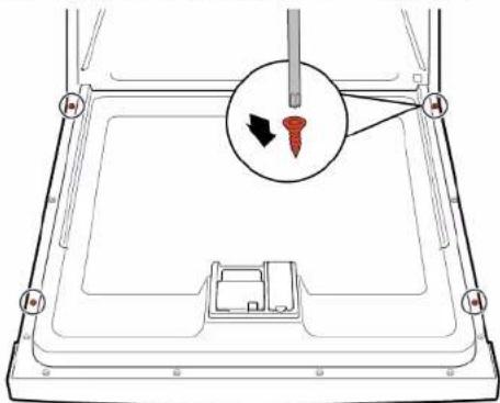
Diagram of a device with a screwdriver inserted into a tray, showing a close-up of the screw (no text or symbols present)

BOSCH SHI4HCS48E - TÄHELEPANU! - 2

Remont

    1. Tehke uks veidi lahti (1).
  1. Kinnitage pöhjarennis olevasse soonde (2).

  2. Sulgege aeglaselt uks (3).

Technical diagram showing mechanical assembly steps with numbered annotations indicating sequence of components

4.14.2 Aluspaneeli paigaldamine

BOSCH SHI4HCS48E - Aluspaneeli paigaldamine - 1

Remont

4.

Mechanical assembly diagram showing a red lever mechanism with labeled parts (1 and 2), no readable text or symbols present.

    1. Pange kruvikeeraja metallpiduri alla (1)
  1. Vabastage ettevaatlikult metallklamber (2).
Technical diagram of a mechanical assembly with numbered components and directional arrow indicating motion or force

BOSCH SHI4HCS48E - Remont - 3

Remont

4.16.2 Ülevoolutoru paigaldamine

Technical diagram showing mechanical assembly with numbered components and directional arrows indicating motion or flow

BOSCH SHI4HCS48E - Ülevoolutoru paigaldamine - 2

Remont

3D diagram of a car door frame with red and black arrows indicating airflow or movement (no text or symbols)

BOSCH SHI4HCS48E - Remont - 2

Remont

  1. Kinnitage uksehing kruvidega.
  2. Paigutage sisemine uks uksehingele.
  3. Kinnitage sisemine uks kruvidega.

4.17.2 Sisemise ukse paigaldamine

4.18.2 Uksehinge paigaldamine

BOSCH SHI4HCS48E - Uksehinge paigaldamine - 1

Technical diagram showing mechanical assembly with numbered components and directional arrows indicating motion or movement.

2.

Close-up of a red mechanical bracket with green cable and arrow indicating connection (no text or symbols)

BOSCH SHI4HCS48E - Uksehinge paigaldamine - 4

Remont

BOSCH SHI4HCS48E - Remont - 1

Remont

4.

Pure technical line drawing of curved pipe or channel sections without any text, numbers, or symbols

BOSCH SHI4HCS48E - Remont - 2

Remont

4.21 Tule EmotionLight vahetamine

Diagram showing a device's internal components with numbered annotations indicating parts of the main body and a tool.

  1. Eemaldage EmotionLight seadmest.

4.21.2 Tule EmotionLight paigaldamine

  1. Pange hoidik loputuspaagi raamile (1).
Technical diagram showing a device's internal components with numbered annotations indicating parts of the main body and parts of the rear panel.

BOSCH SHI4HCS48E - Tule EmotionLight paigaldamine - 2

Remont

  1. Kinnitage haak (2).

3.

BOSCH SHI4HCS48E - Remont - 1

TÄHELEPANUI

Vale paigaldus!

BOSCH SHI4HCS48E - TÄHELEPANUI - 1

Remont

Close-up of a mechanical component with a red vertical stripe and black arrow indicating a section (no text or symbols visible)

Joonis 3: Lame kaabel
4. Paigaldage pistik.

BOSCH SHI4HCS48E - Remont - 2

Remont

4.22 Tule TimeLight vahetamine

Technical diagram of a mechanical assembly with numbered components and highlighted parts

    1. Vötke tagaküljel haak lahti (1).
  1. Eemaldage valguskiud (2).

3D mechanical assembly diagram showing internal components with numbered parts (1 and 2), no readable text or symbols present.

3D mechanical assembly diagram showing internal components with no visible text or symbols

BOSCH SHI4HCS48E - Tule TimeLight vahetamine - 4

Remont

4.23.2 Süvendivalgustuse Gap Illumination paigaldamine

  1. Käännä klipsi ylös.

Mechanical diagram showing a lever mechanism with a curved arrow indicating rotational motion (no text or symbols present)

BOSCH SHI4HCS48E - Süvendivalgustuse Gap Illumination paigaldamine - 2

Korjaus

Korjaus

Technical diagram of a refrigerator with numbered parts and directional arrows indicating components

3.

Diagram showing a hand inserting a screw into a device with a magnified view of the screw and its insertion direction.

4.14.2 Alapaneelin asentaminen

BOSCH SHI4HCS48E - Alapaneelin asentaminen - 1

Korjaus

4.

Mechanical assembly diagram showing a red lever mechanism with labeled parts (no text or symbols present)

BOSCH SHI4HCS48E - Korjaus - 2

Korjaus

BOSCH SHI4HCS48E - Korjaus - 1

Korjaus

3D diagram of a mechanical component with red and black arrows indicating directional flow or movement (no text or symbols)

BOSCH SHI4HCS48E - Korjaus - 2

Korjaus

4.18.2 Luukun saranan asennus

BOSCH SHI4HCS48E - Luukun saranan asennus - 1

Technical diagram showing mechanical assembly with numbered components and directional arrows indicating motion or movement.

2.

Close-up of a red mechanical bracket with green cable and arrow indicating assembly (no text or symbols)

BOSCH SHI4HCS48E - Luukun saranan asennus - 4

Korjaus

Korjaus

4.

Pure technical line drawing of curved structural elements without any text or symbols

BOSCH SHI4HCS48E - Korjaus - 2

Korjaus

BOSCH SHI4HCS48E - Korjaus - 1

Korjaus

BOSCH SHI4HCS48E - Korjaus - 1

Korjaus

Close-up of a mechanical component with a red vertical stripe and black arrow indicating a cut or section (no text or symbols visible)

    1. Irrota kiinnitin takaa (1).
  1. Poista valokuitu (2).

3D mechanical assembly diagram showing internal components with numbered callouts (1 and 2), no readable text or symbols present.

3D mechanical assembly diagram showing internal components with no visible text or symbols

BOSCH SHI4HCS48E - Korjaus - 4

Korjaus

2021-03-22_9001630792 Copyright par BSH Hausgeräte GmbH Pages 338 à 989

BOSCH SHI4HCS48E - Korjaus - 1

Réparation

BOSCH SHI4HCS48E - Réparation - 1

Réparation

4.3 Changer le tiroir Vario

BOSCH SHI4HCS48E - Changer le tiroir Vario - 1

Réparation

4.7.2 Connecter câble de raccordement

BOSCH SHI4HCS48E - Connecter câble de raccordement - 1

ATTENTION!

3.

Diagram showing a hand inserting a screw into a device with a magnified view of the screw and its insertion direction.

BOSCH SHI4HCS48E - ATTENTION! - 2

Réparation

BOSCH SHI4HCS48E - Réparation - 1

Réparation

4.

Mechanical assembly diagram showing a red pipe connection with labeled parts (no text or symbols present)

BOSCH SHI4HCS48E - Réparation - 2

Réparation

BOSCH SHI4HCS48E - Réparation - 1

Réparation

3D diagram of a mechanical component with red and black arrows indicating directional flow or movement (no text or symbols)

BOSCH SHI4HCS48E - Réparation - 2

Réparation

2021-03-22_9001630792 Copyright par BSH Hausgeräte GmbH Pages 361 à 989

2.

Close-up of a red mechanical bracket with green cable and arrow indicating connection (no text or symbols)

BOSCH SHI4HCS48E - Réparation - 2

Réparation

BOSCH SHI4HCS48E - Réparation - 1

Réparation

4.

Pure technical line drawing of curved pipe or channel sections without any text, numbers, or symbols

BOSCH SHI4HCS48E - Réparation - 2

Réparation

4.21 Changer l'EmotionLight

Technical diagram showing a disassembly or repair process with labeled components and directional arrows indicating movement.

BOSCH SHI4HCS48E - Changer l'EmotionLight - 2

Réparation

  1. Encliqueter l'ergot (2).

3.

BOSCH SHI4HCS48E - Réparation - 1

ATTENTION!

Installation non conforme.

BOSCH SHI4HCS48E - ATTENTION! - 1

Réparation

Close-up of a mechanical component with a red vertical stripe and black arrow indicating a section (no text or symbols visible)

Fig. 3: Câble plat

BOSCH SHI4HCS48E - Réparation - 2

Réparation

4.23.2 Monter le Gap illumination

BOSCH SHI4HCS48E - Monter le Gap illumination - 1

Instandsetzen

BOSCH SHI4HCS48E - Instandsetzen - 1

Instandsetzen

3.

Diagram showing a hand inserting a screw into a device with a magnified view of the screw and its insertion direction.

4.14.2 Sockelblende montieren

BOSCH SHI4HCS48E - Sockelblende montieren - 1

Instandsetzen

4.15 Sockelblech tauschen

Technical diagram showing a mechanical assembly with numbered components and directional arrows indicating motion or flow.

4.

Mechanical assembly diagram showing a red lever mechanism with labeled parts (1 and 2), no readable text or symbols present.

BOSCH SHI4HCS48E - Sockelblech tauschen - 3

Instandsetzen

BOSCH SHI4HCS48E - Instandsetzen - 1

Instandsetzen

3D diagram of a vehicle door with red and black arrows indicating airflow or movement (no text or symbols)

BOSCH SHI4HCS48E - Instandsetzen - 2

Instandsetzen

2.

Close-up of a red mechanical bracket with green cable and arrow indicating connection (no text or symbols)

BOSCH SHI4HCS48E - Instandsetzen - 2

Instandsetzen

4.

Pure technical line drawing of curved pipe or channel sections without any text, numbers, or symbols

BOSCH SHI4HCS48E - Instandsetzen - 2

Instandsetzen

4.21 EmotionLight tauschen

Diagram showing a device's internal components with numbered annotations indicating parts of the main body and parts of the device.

BOSCH SHI4HCS48E - EmotionLight tauschen - 2

Instandsetzen

BOSCH SHI4HCS48E - Instandsetzen - 1

Instandsetzen

Close-up of a mechanical component with a red vertical stripe and black arrow indicating a cut or section (no text or symbols visible)

Abb. 3: Flaches Kabel

  1. Stecker einstecken.

BOSCH SHI4HCS48E - Instandsetzen - 2

Instandsetzen

4.22 TimeLight tauschen

Technical diagram showing a mechanical assembly with numbered components and highlighted parts, likely illustrating a machining or assembly process.

BOSCH SHI4HCS48E - TimeLight tauschen - 2

Instandsetzen

4.23.2 Gap Illumination montieren

BOSCH SHI4HCS48E - Gap Illumination montieren - 1

Επισκευή

BOSCH SHI4HCS48E - Επισκευή - 1

Επισκευή

BOSCH SHI4HCS48E - Επισκευή - 1

Επισκευή

3.

Diagram showing a hand inserting a screw into a device with a magnified view of the screw and its insertion direction.

BOSCH SHI4HCS48E - Επισκευή - 2

Επισκευή

BOSCH SHI4HCS48E - Επισκευή - 1

Επισκευή

4.

Mechanical assembly diagram showing a red lever mechanism with labeled parts (1 and 2), no readable text or symbols present.

BOSCH SHI4HCS48E - Επισκευή - 2

Επισκευή

BOSCH SHI4HCS48E - Επισκευή - 1

Επισκευή

3D diagram of a car door frame with red and black arrows indicating directional movement (no text or symbols)

2021-03-22_9001630792 Copyright by BSH Hausgeräte GmbH Σελίδα 442 απτό 989

BOSCH SHI4HCS48E - Επισκευή - 2

Επισκευή

2021-03-22_9001630792 Copyright by BSH Hausgeräte GmbH Σελίδα 444 απτό 989

2.

Close-up of a red mechanical bracket with green cable and arrow indicating assembly (no text or symbols)

2021-03-22_9001630792 Copyright by BSH Hausgeräte GmbH Σελίδα 445 απτό 989

BOSCH SHI4HCS48E - Επισκευή - 2

Επισκευή

BOSCH SHI4HCS48E - Επισκευή - 1

Επισκευή

4.

Pure technical line drawing of curved pipe or channel sections without any text, numbers, or symbols

BOSCH SHI4HCS48E - Επισκευή - 2

Επισκευή

BOSCH SHI4HCS48E - Επισκευή - 1

Επισκευή

BOSCH SHI4HCS48E - Επισκευή - 1

Επισκευή

Close-up of a mechanical component with a red vertical stripe and black arrow pointing to a section (no text or symbols visible)

3D mechanical assembly diagram showing internal components with no visible text or symbols

BOSCH SHI4HCS48E - Επισκευή - 3

Επισκευή

  1. Hajtsa fel a fület.

Mechanical diagram showing a lever mechanism with a curved arrow indicating rotational motion (no text or symbols)

BOSCH SHI4HCS48E - Επισκευή - 2

Javítás

BOSCH SHI4HCS48E - Javítás - 1

Javítás

3.

Diagram showing a hand inserting a screw into a device with a magnified inset highlighting the screw's direction.

BOSCH SHI4HCS48E - Javítás - 2

Javítás

BOSCH SHI4HCS48E - Javítás - 1

Javítás

4.

Mechanical assembly diagram showing a red lever mechanism with labeled parts (1 and 2), no readable text or symbols present.

BOSCH SHI4HCS48E - Javítás - 2

Javítás

BOSCH SHI4HCS48E - Javítás - 1

Javítás

3D diagram of a mechanical component with red and black arrows indicating directional flow or movement (no text or symbols)

BOSCH SHI4HCS48E - Javítás - 2

Javítás

2.

Close-up of a red mechanical bracket with green cable and arrow indicating connection (no text or symbols)

BOSCH SHI4HCS48E - Javítás - 2

Javítás

BOSCH SHI4HCS48E - Javítás - 1

Javítás

4.

Pure technical line drawing of curved pipe or channel sections without any text, numbers, or symbols

BOSCH SHI4HCS48E - Javítás - 2

Javítás

BOSCH SHI4HCS48E - Javítás - 1

Javítás

BOSCH SHI4HCS48E - Javítás - 1

Javítás

Close-up of a mechanical component with a red vertical stripe and black arrow indicating a cut or section (no text or symbols visible)

Ábra 3: Lapos kábel

3D mechanical assembly diagram showing internal components with no visible text or symbols

BOSCH SHI4HCS48E - Javítás - 3

Javítás

BOSCH SHI4HCS48E - Javítás - 1

Riparazione

BOSCH SHI4HCS48E - Riparazione - 1

Riparazione

Riparazione

3.

Diagram showing a hand inserting a screw into a device with a magnified view of the screw and its insertion direction.

Riparazione

Riparazione

4.

Mechanical assembly diagram showing a red lever mechanism with labeled parts (1 and 2), no readable text or symbols present.

Riparazione

BOSCH SHI4HCS48E - Riparazione - 1

Riparazione

3D diagram of a mechanical component with red and black arrows indicating directional flow or movement (no text or symbols)

Riparazione

2.

Close-up of a red mechanical bracket with green cable and arrow indicating assembly (no text or symbols)

Riparazione

Riparazione

4.

Pure technical line drawing of curved structural elements without any text, numbers, or symbols

BOSCH SHI4HCS48E - Riparazione - 2

Riparazione

BOSCH SHI4HCS48E - Riparazione - 1

Riparazione

Riparazione

Close-up of a mechanical component with a red vertical stripe and black arrow indicating a section (no text or symbols visible)

Fig. 3: Cavo piatto

  1. Inserire la spina.

BOSCH SHI4HCS48E - Riparazione - 2

Riparazione

Riparazione

  1. Uzlokiet balstu.

Mechanical diagram showing a lever mechanism with a curved arrow indicating rotational motion (no text or symbols)

BOSCH SHI4HCS48E - Riparazione - 2

Remonts

4.3 Atvilktnes varioDrawer nomaiņa

4.3.1 Atvilktnes varioDrawer nonemšana

  1. lespiediet roktura plāksnes.

3D structural diagram of a steel-framed metal grid panel with an inset showing a close-up of a blue door component (no text or symbols visible)

BOSCH SHI4HCS48E - Atvilktnes varioDrawer nonemšana - 2

Remonts

3.

BOSCH SHI4HCS48E - Remonts - 1

Pieturiet durvis aiz sāniem.

BOSCH SHI4HCS48E - Remonts - 2

Remonts

    1. Paveriet durvis (1).
  1. Nostipriniet pamatnes iedobes rievā (2).

  2. Lēni aizveriet durvis (3).

Technical diagram showing assembly steps of a mechanical component with numbered annotations indicating different states or features.

Remonts

4.

Mechanical assembly diagram showing a red lever mechanism with labeled parts (1 and 2), no readable text or symbols present.

BOSCH SHI4HCS48E - Remonts - 2

Remonts

BOSCH SHI4HCS48E - Remonts - 1

Remonts

3D diagram of a mechanical component with red and black arrows indicating directional flow or movement (no text or symbols)

Remonts

2.

Close-up of a red mechanical bracket with green cable and arrow indicating assembly (no text or symbols)

BOSCH SHI4HCS48E - Remonts - 2

Remonts

BOSCH SHI4HCS48E - Remonts - 1

Remonts

4.

Pure architectural or structural lines drawing without any text, numbers, or symbols

BOSCH SHI4HCS48E - Remonts - 2

Remonts

4.21 Gaismekla EmotionLight nomaiña

Technical diagram showing a disassembly or repair process with labeled components and directional arrows indicating movement.

  1. Nonemiet gaismekli EmotionLight no ierices.

BOSCH SHI4HCS48E - Gaismekla EmotionLight nomaiña - 2

Remonts

BOSCH SHI4HCS48E - Remonts - 1

Remonts

Close-up of a mechanical component with a red vertical stripe and black arrow pointing to a section (no text or symbols visible)

Att. 3: Lentveida kabelis

  1. lespraudiet spraudni.

BOSCH SHI4HCS48E - Remonts - 2

Remonts

4.22 Gaismekla TimeLight nomaiņa

Technical diagram showing a mechanical assembly with numbered components and a magnified inset highlighting a red component.

  1. Izvelciet gaismekla TimeLight moduli no vadotnes uz augšu (2).
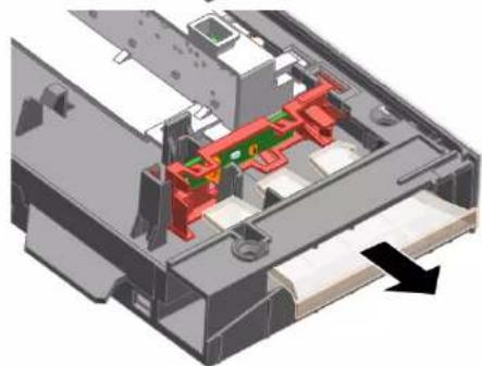
3D mechanical assembly diagram showing internal components with no visible text or symbols

BOSCH SHI4HCS48E - Gaismekla TimeLight nomaiņa - 3

Remonts

BOSCH SHI4HCS48E - Remonts - 1

Remontas

BOSCH SHI4HCS48E - Remontas - 1

Remontas

4.7.2 Maitinimo laido prijungimas

BOSCH SHI4HCS48E - Maitinimo laido prijungimas - 1

DÉMESIO!

  1. Pakelkite siurblio dangtelj kampu vidaus link ir nuimkite.

3.

Diagram showing a hand inserting a screw into a device with a magnified view of the screw and its insertion direction.

BOSCH SHI4HCS48E - DÉMESIO! - 2

Remontas

  1. Nukelkite skydelj.

  2. Nuimkite kojeles patraukdami i priekj (1).
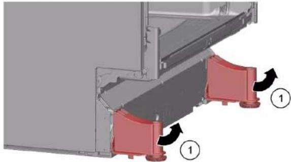
Mechanical assembly diagram showing red components mounted on a gray frame, with numbered arrows indicating motion (no text or symbols present)

BOSCH SHI4HCS48E - Remontas - 2

Remontas

4.15 Pagrindo lizdy dangtelio keitimas

Technical diagram showing a mechanical assembly with numbered components and directional arrows indicating motion or flow.

4.

Mechanical assembly diagram showing a red lever mechanism with labeled parts (1 and 2), no readable text or symbols present.

BOSCH SHI4HCS48E - Pagrindo lizdy dangtelio keitimas - 3

Remontas

BOSCH SHI4HCS48E - Remontas - 1

Remontas

3D diagram of a mechanical component with red and black arrows indicating directional flow or movement (no text or symbols)

BOSCH SHI4HCS48E - Remontas - 2

Remontas

2.

Close-up of a red mechanical bracket with green cable and arrow indicating connection (no text or symbols)

BOSCH SHI4HCS48E - Remontas - 2

Remontas

BOSCH SHI4HCS48E - Remontas - 1

Remontas

4.

Pure technical line drawing of curved pipe or channel sections without any text, numbers, or symbols

BOSCH SHI4HCS48E - Remontas - 2

Remontas

4.21 „EmotionLight“ keitimas

Technical diagram showing a device's internal components with numbered annotations indicating parts of the main body and adjustment.

BOSCH SHI4HCS48E - „EmotionLight“ keitimas - 2

Remontas

BOSCH SHI4HCS48E - Remontas - 1

Remontas

Close-up of a mechanical component with a red vertical stripe and black arrow indicating a cut or section (no text or symbols visible)

  1. [stumkite „TimeLight“ modulj j kreipiklj (2).
  2. Prijunkite elektros jungti.

BOSCH SHI4HCS48E - Remontas - 2

Remontas

4.23 „Gap illumination“ keitimas

Reikalavimas.

BOSCH SHI4HCS48E - Reikalavimas. - 1

Remontas

4.23.2 „Gap illumination“ montavimas

2021-03-22_9001630792 Copyright BSH Hausgeräte GmbH Side 627 av 989

  1. Fell opp klemmen.

Mechanical diagram showing a lever mechanism with a curved arrow indicating rotational motion (no text or symbols)

BOSCH SHI4HCS48E - Remontas - 2

Reparasjon

BOSCH SHI4HCS48E - Reparasjon - 1

Reparasjon

Reparasjon

4.4.2 Montering av spylearm

Kontroller at det ikke faller uvedkommende gjenstander ned i bunnpannen.

  1. Trekk mikrofilteret ned for à ta det ut.
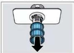
Diagram of a mechanical component with a blue cylindrical assembly and black downward arrow (no text or symbols)

4.5.2 Montering av filtre

Bilde 1: Helintegrert
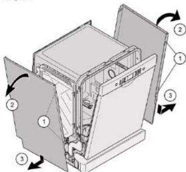
Technical diagram of a refrigerator interior with numbered components and directional arrows indicating flow or movement.

Bilde 2: Helintegrert

Technical diagram showing a mechanical assembly with numbered components and directional arrows indicating motion or assembly.

  1. Trykk sidepanelet inn på apparatet (2).
  2. Sikre sidepanelet med skruene (3).

BOSCH SHI4HCS48E - Montering av filtre - 3

Reparasjon

3.

BOSCH SHI4HCS48E - Reparasjon - 1

Sikre døren ved å holde den fast på en side.

Fjem to skruer.
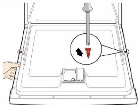
Diagram showing a hand inserting a screw into a device with a magnified view of the screw and its insertion direction.

Reparasjon

  1. Demonter betjeningspanelet.
    1. Åpne døren litt (1).
  1. Fest den i sporet i bunnkaret (2).

  2. Lukk døren sakte (3).

Technical diagram showing mechanical assembly steps with numbered annotations indicating sequence of components

Reparasjon

4.

Mechanical assembly diagram showing a red pipe connection with labeled parts (no text or symbols present)

BOSCH SHI4HCS48E - Reparasjon - 2

Reparasjon

BOSCH SHI4HCS48E - Reparasjon - 1

Reparasjon

3D diagram of a car door with red and black arrows indicating airflow or movement (no text or symbols)

BOSCH SHI4HCS48E - Reparasjon - 2

Reparasjon

2021-03-22_9001630792 Copyright BSH Hausgeräte GmbH Side 650 av 989

  1. Løsne jordkoblingen på dørhengselen.

Mechanical assembly diagram showing a red bracket mounted on a metal frame with a green cable and arrow indicating connection (no text or symbols present)

2.

Close-up of a red mechanical bracket with green cable and arrow indicating assembly (no text or symbols)

BOSCH SHI4HCS48E - Reparasjon - 3

Reparasjon

Reparasjon

4.19.2 Montering av dørpakningen

4.

Pure technical line drawing of curved structural elements without any text or symbols

BOSCH SHI4HCS48E - Montering av dørpakningen - 2

Reparasjon

BOSCH SHI4HCS48E - Reparasjon - 1

Reparasjon

  1. Fest festekroken (2).

3.

BOSCH SHI4HCS48E - Reparasjon - 1

OBS!

Feil montering!

Skade på kabelen i området rundt dørhengselen.

Reparasjon
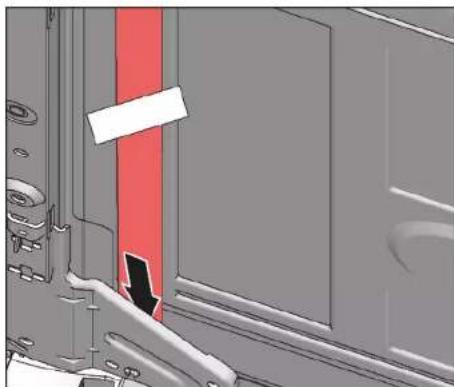
Mechanical assembly diagram showing a red highlighted section with a black arrow pointing to a component (no text or symbols present)

Bilde 3: Flat kabel

  1. Sett i pluggen.

BOSCH SHI4HCS48E - Reparasjon - 2

Reparasjon

  1. Skyv TimeLight-modulen inn i føringen (2).
  2. Koble til den elektriske tilkoblingen.

BOSCH SHI4HCS48E - Reparasjon - 1

Reparasjon

Reparasjon

    1. Løsne låsekroken (1).
  1. Løft opp kretskortet med holderen og fjern det fra betjeningsmodulrammen (2).
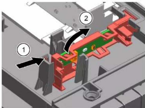
Technical diagram of a mechanical assembly with numbered components, likely illustrating a device or assembly step.

  1. Złożyć klips.

Mechanical diagram showing a lever mechanism with a curved arrow indicating rotational motion (no text or symbols)

BOSCH SHI4HCS48E - Reparasjon - 3

Naprawy

4.3 Wymiana szuflady varioDrawer

BOSCH SHI4HCS48E - Wymiana szuflady varioDrawer - 1

Naprawy

Rys. 1: Do zabudowy
Technical diagram of a refrigerator interior with numbered components and directional arrows indicating flow or movement.

Rys. 2: Do zabudowy
Technical diagram showing a mechanical assembly with numbered components and directional arrows indicating motion or assembly.

3.

Diagram showing a hand inserting a screw into a device with a magnified view of the screw and its insertion direction.

BOSCH SHI4HCS48E - Naprawy - 4

Naprawy

BOSCH SHI4HCS48E - Naprawy - 1

Naprawy

4.

Mechanical assembly diagram showing a red lever mechanism with labeled parts (1 and 2), no readable text or symbols present.

BOSCH SHI4HCS48E - Naprawy - 2

Naprawy

BOSCH SHI4HCS48E - Naprawy - 1

Naprawy

3D diagram of a car door with red and black arrows indicating airflow or movement, no text or symbols present

BOSCH SHI4HCS48E - Naprawy - 2

Naprawy

2.

Close-up of a red mechanical bracket with green cable and arrow indicator (no text or symbols)

BOSCH SHI4HCS48E - Naprawy - 2

Naprawy

BOSCH SHI4HCS48E - Naprawy - 1

Naprawy

4.

Pure technical line drawing of curved pipe or channel sections without any text, numbers, or symbols

BOSCH SHI4HCS48E - Naprawy - 2

Naprawy

BOSCH SHI4HCS48E - Naprawy - 1

Naprawy

BOSCH SHI4HCS48E - Naprawy - 1

Naprawy

Close-up of a mechanical component with a red vertical stripe and black arrow indicating a section (no text or symbols visible)

BOSCH SHI4HCS48E - Naprawy - 2

Naprawy

4.17.1 Remover a porta interior 731

4.17.2 Instalar a porta interior 731

4.18 Substituir a dobradiça da porta 732

4.18.1 Remover a dobradiça da porta 732

4.18.2 Instalar a dobradiça da porta....732

4.2.3 Instalar o inserto de vaporeira

BOSCH SHI4HCS48E - Instalar o inserto de vaporeira - 1

Reparação

4.3 Substituir a gaveta vario

4.3.1 Remover a gaveta vario

BOSCH SHI4HCS48E - Remover a gaveta vario - 1

Reparação

4.4.2 Instalar o braço aspersor

4.5.2 Instalar os filtros

  1. Pressione o painel lateral sobre o aparelho (2).
  2. Fixe o painel lateral com parafusos (3).

BOSCH SHI4HCS48E - Instalar os filtros - 1

Reparação

4.11 Substituir a porta exterior

Pré-requisito:

3.

Diagram showing a hand inserting a screw into a device with a magnified view of the screw and its insertion direction.

4.11.2 Instalar a porta exterior

Technical diagram of a refrigerator interior with labeled components and directional arrows indicating parts of the door.

  1. Pressione a porta exterior contra a porta interior e segure (2).

4.

Diagram showing a hand operating a screwdriver inside a device with a magnified view of the tool's tip and arrow indicating direction.

  1. Fixe a porta exterior com quatro parafusos (4 parafusos de metal de 11 mm).
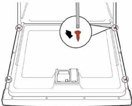
Diagram of a device with a screw and a magnified inset showing the screw being inserted (no text or symbols present)

BOSCH SHI4HCS48E - Instalar a porta exterior - 4

Reparação

4.12 Substituir o painel de comandos

Diagram of a device interior with numbered components and colored wiring, likely illustrating a mechanical or electrical layout.

  1. Remova o painel de comandos.

4.12.2 Instalar o painel de comandos

BOSCH SHI4HCS48E - Instalar o painel de comandos - 1

Use os parafusos 4 x 16 mm.

4.14.2 Instalar o painel inferior

BOSCH SHI4HCS48E - Instalar o painel inferior - 1

Reparação

4.15 Substituir a placa da tomada de base

Technical diagram showing a mechanical assembly with numbered components and directional arrows indicating motion or flow.

4.

Mechanical assembly diagram showing a red lever mechanism with labeled parts (1 and 2), no readable text or symbols present.

BOSCH SHI4HCS48E - Substituir a placa da tomada de base - 3

Reparação

    1. Insira a chave de parafusos sob o grampo de metal (1).
  1. Solte o clipe de metal suavemente (2).
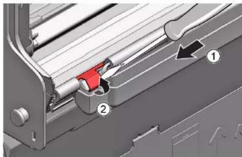
Mechanical assembly diagram showing a lever mechanism with labeled parts (1 and 2), no readable text or symbols present.

4.16.2 Instalar a calha de transbordamento.

Technical diagram showing mechanical assembly with numbered components and directional arrows indicating motion or movement.

BOSCH SHI4HCS48E - Reparação - 3

Reparação

3D diagram of a car door frame with red and black arrows indicating directional movement (no text or symbols)

BOSCH SHI4HCS48E - Reparação - 2

Reparação

4.17 Substituir a porta interior

Pré-requisito:

4.17.1 Remover a porta interior

4.17.2 Instalar a porta interior

4.18.2 Instalar a dobradiça da porta

BOSCH SHI4HCS48E - Instalar a dobradiça da porta - 1

Technical diagram showing mechanical assembly with numbered components and directional arrows indicating motion or movement.

2.

Close-up of a red mechanical bracket with green cable and arrow indicating assembly (no text or symbols)

BOSCH SHI4HCS48E - Instalar a dobradiça da porta - 4

Reparação

  1. Desprenda a calha de transbordamento.

3D mechanical assembly diagram showing a sliding mechanism with a red component and housing (no text or symbols)

BOSCH SHI4HCS48E - Reparação - 2

Reparação

4.

Pure technical line drawing of curved structural elements without any text or symbols

BOSCH SHI4HCS48E - Reparação - 2

Reparação

4.21 Substituir o EmotionLight

Technical diagram showing a disassembly or repair process with labeled components and directional arrows indicating movement.

BOSCH SHI4HCS48E - Substituir o EmotionLight - 2

Reparação

  1. Engate o gancho de encaixe (2).

3.

Close-up of a mechanical component with a red vertical rod and black arrow pointing to a detail (no visible text or symbols)

BOSCH SHI4HCS48E - Reparação - 2

Reparação

Close-up of a mechanical component with a red vertical stripe and black arrow indicating a cut or section (no text or symbols visible)

Fig. 3: Cabo plano

  1. Insira a ficha.

BOSCH SHI4HCS48E - Reparação - 2

Reparação

4.22 Substituir o TimeLight

Technical diagram showing a mechanical assembly with numbered components and highlighted parts, likely illustrating a machining or assembly process.

4.23.1 Remover a Gap Illumination

    1. Desprenda o gancho de encaixe atrás (1).
  1. Remova a fibra ótica (2).

3D mechanical assembly diagram showing internal components and a directional arrow (no text or symbols)

BOSCH SHI4HCS48E - Remover a Gap Illumination - 2

Reparação

4.23.2 Instalar a Gap Illumination

BOSCH SHI4HCS48E - Instalar a Gap Illumination - 1

Repararea

BOSCH SHI4HCS48E - Repararea - 1

Repararea

Repararea

4.5.2 Montarea filtrelor

3.

Diagram showing a hand inserting a screw into a device with a magnified view of the screw and its insertion direction.

BOSCH SHI4HCS48E - Montarea filtrelor - 2

Repararea

  1. Ridicati panoul.

BOSCH SHI4HCS48E - Repararea - 1

Repararea

4.

Mechanical assembly diagram showing a red lever mechanism with labeled parts (1 and 2), no readable text or symbols present.

BOSCH SHI4HCS48E - Repararea - 2

Repararea

BOSCH SHI4HCS48E - Repararea - 1

Repararea

3D diagram of a car door frame with red and black arrows indicating airflow or movement (no text or symbols)

BOSCH SHI4HCS48E - Repararea - 2

Repararea

4.18.2 Montarea balamalei uşii

BOSCH SHI4HCS48E - Montarea balamalei uşii - 1

Technical diagram showing mechanical assembly with numbered components and directional arrows indicating motion or movement.

2.

Close-up of a red mechanical bracket with green cable and arrow indicating assembly (no text or symbols)

BOSCH SHI4HCS48E - Montarea balamalei uşii - 4

Repararea

  1. Detaşati jgheabul de preaplin.

3D mechanical assembly diagram showing a sliding mechanism with a red component and housing (no text or symbols)

  1. Ridicati jgheabul de preaplin.

3D mechanical assembly diagram showing internal components and mounting features (no text or symbols visible)

Repararea

4.19.2 Montarea garniturii uşii

4.

Pure technical line drawing of curved structural elements without any text or symbols

BOSCH SHI4HCS48E - Montarea garniturii uşii - 2

Repararea

4.21 Înlocuirea lămpii EmotionLight

Diagram showing a device's internal structure with labeled parts and directional arrows indicating movement or assembly.

BOSCH SHI4HCS48E - Înlocuirea lămpii EmotionLight - 2

Repararea

BOSCH SHI4HCS48E - Repararea - 1

Repararea

Close-up of a mechanical component with a red vertical stripe and black arrow indicating a section (no text or symbols visible)

Fig. 3: Cablu plat

  1. Introduceti stecherul.

BOSCH SHI4HCS48E - Repararea - 2

Repararea

BOSCH SHI4HCS48E - Repararea - 1

Repararea

4.23.2 Montarea lămpii Gap Illumination

  1. Vpredu mierne zdvihnite pracovnú plochu (3).
  2. Pracovnú plochu odtlačte smerom dozadu (4).
  3. Odstráňte pracovnú plochu.
  1. Zacvaknite úchytku na pridržanie pohárov na svoje miesto.
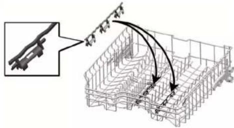
Technical diagram showing a mechanical assembly with labeled components and directional arrows indicating motion or force vectors.

  1. Vyklopte úchytku.

Mechanical diagram showing a lever mechanism with a curved arrow indicating rotational motion (no text or symbols)

BOSCH SHI4HCS48E - Montarea lămpii Gap Illumination - 3

Oprava

BOSCH SHI4HCS48E - Oprava - 1

Oprava

  1. Opatrne ohnite vodiace držadlá smerom von.
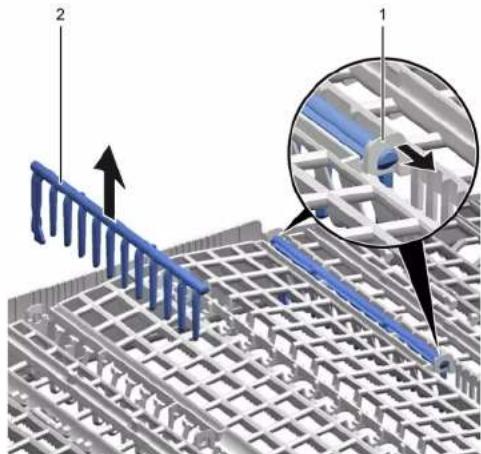
3D architectural diagram showing structural grid and rebar layout with labeled components (no text or symbols present)

  1. Vytiahnite sklopné drôty z držiakov.

  2. Vytlačte kovový rám na prednej časti z držadiel.
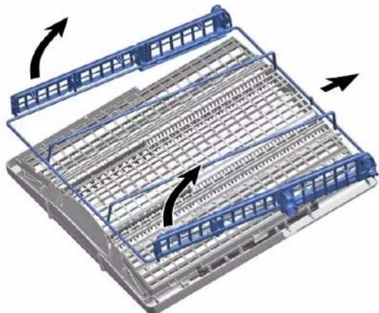
3D diagram of a mechanical assembly with blue structural elements and directional arrows indicating motion (no text or symbols)

4.4.2 Montáž ostrekovacieho ramena

  1. Vložte spodné ostrekovacie rameno.
    Ostrekovacie rameno zacvakne na svoje miesto.
  2. Vložte horné ostrekovacie rameno a napevno ho zaskrutkujte na svoje miesto.

BOSCH SHI4HCS48E - Montáž ostrekovacieho ramena - 1

Oprava

4.5 Výmena filtrov

4.5.1 Odoberanie filtra

Ostrekovacia hlavica na plech na pečenie zacvakne na svoje miesto.

BOSCH SHI4HCS48E - Odoberanie filtra - 1

Oprava

Viečko čerpadla zacvakne na svoje miesto.

BOSCH SHI4HCS48E - Oprava - 1

Oprava

Obr. 1: Plne integrované
Technical diagram of a multi-chamber refrigerator with numbered components and directional arrows indicating internal flow or movement.

Obr. 2: Plne integrované
Technical diagram showing a mechanical assembly with numbered components and directional arrows indicating motion or assembly.

3.

BOSCH SHI4HCS48E - Oprava - 3

Dvierka zaistite a z jednej strany pridržte.

  1. Odpojte uzemňovací kábel (3) (voliteľné).
  2. Otvorte dvierka spotrebiča.
  3. Zabezpečte, aby ovládací panel nespadol (pridržte ho).

  4. Odstráňte šest' skrutiek.

Diagram of a device interior with screw and control panel, no text or symbols present

  1. Proces zopakujte na druhej strane spotrebiča.

BOSCH SHI4HCS48E - Oprava - 5

Oprava

  1. Panel zdvihnite.

BOSCH SHI4HCS48E - Oprava - 1

Oprava

4.

Mechanical assembly diagram showing a red pipe connection with labeled parts (no text or symbols present)

BOSCH SHI4HCS48E - Oprava - 2

Oprava

3D mechanical assembly diagram showing red and black arrows indicating directional flow (no text or symbols)

2.

3D mechanical assembly diagram showing red bracket and green cable connection (no text or symbols)

BOSCH SHI4HCS48E - Oprava - 3

Oprava

4.19.2 Montáž tesnenia dvierok

4.

Pure technical line drawing of curved pipe or channel sections without any text, numbers, or symbols

BOSCH SHI4HCS48E - Montáž tesnenia dvierok - 2

Oprava

4.21 Výmena EmotionLight

Technical diagram showing a device's internal components with numbered annotations indicating parts of the main body and adjustment.

  1. Odoberte držadlo smerom nahor (2).
  2. Odpojte zástrčku z konektora (vpravo dole na čelnej strane spotrebiča).
  1. Odoberte EmotionLight zo spotrebiča.

4.21.2 Montáž osvetlenia EmotionLight

BOSCH SHI4HCS48E - Montáž osvetlenia EmotionLight - 1

Oprava

BOSCH SHI4HCS48E - Oprava - 1

Oprava

Close-up of a mechanical component with a red vertical stripe and black arrow indicating a cut or section (no text or symbols visible)

  1. Potiahnite modul TimeLight nahor von z vodidla (2).

4.22.2 Montáž TimeLight

  1. Zatlačte modul TimeLight do vodidla (2).
  2. Vytvorte elektrické pripojenie.

BOSCH SHI4HCS48E - Montáž TimeLight - 1

Oprava

4.23 Výmena Gap illumination

Požiadavka:

BOSCH SHI4HCS48E - Požiadavka: - 1

Oprava

4.23.2 Montáž Gap illumination

  1. Dotiahnite ho až do zacvaknutia.

CLICK

  1. Namontujte svetelné vlákno a dotiahnite ho až do zacvaknutia.
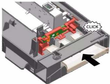
3D mechanical assembly diagram showing internal components with a highlighted 'CLICK' button (no text or symbols beyond the label)

  1. Sprednji del delovne površine nekoliko dvignite (3).
  2. Delovno površino potisnite stran od zadnjega dela (4).
  3. Odstranite delovno površino.
  1. Preklopite nosilec.

Mechanical diagram showing a lever mechanism with a curved arrow indicating rotational motion (no text or symbols)

BOSCH SHI4HCS48E - Montáž Gap illumination - 4

Popravilo

4.3 Zamenjava predalov varioDrawer

4.3.1 Odstranjevanje predalov varioDrawer

BOSCH SHI4HCS48E - Odstranjevanje predalov varioDrawer - 1

Popravilo

  1. Povlecite zložljive paličaste nosilce iz zavihka.

  2. Kovinski okvir pritisnite spredaj ven iz držal.

3D diagram of a mechanical assembly with blue structural elements and directional arrows indicating motion (no text or symbols)

  1. Povlecite kovinski okvir nazaj, ven iz vodila.

4.3.2 Namestitev predala varioDrawer

▶ Namestite v obratnem vrstnem redu.

BOSCH SHI4HCS48E - Namestitev predala varioDrawer - 1

Popravilo

Sl. 1: Popolnoma vgradni
Technical diagram of a multi-chamber refrigerator with numbered components and directional arrows indicating internal flow.

Sl. 2: Popolnoma vgradni

Technical diagram showing a mechanical assembly with numbered components and directional arrows indicating motion or assembly.

  1. Stransko ploščo potisnite na aparat (2).
  2. Stransko ploščo pritrdite z vijaki (3).

BOSCH SHI4HCS48E - Popravilo - 3

Popravilo

4.11 Zamenjava zunanjih vrat

Zahteva:

3.

BOSCH SHI4HCS48E - Zamenjava zunanjih vrat - 1

Vrata pridržite tako, da jih na eni strani primete.

Odstranite dva vijaka.
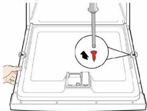
Diagram showing a hand inserting a screw into a device with a magnified view of the screw and its insertion direction.

BOSCH SHI4HCS48E - Zamenjava zunanjih vrat - 3

Popravilo

Zahteva:

  1. Zunanja vrata pritisnite ob notranja vrata in zadržite (2).

4.

BOSCH SHI4HCS48E - Zahteva: - 1

Vrata pridržite tako, da jih na eni strani primete.

BOSCH SHI4HCS48E - Zahteva: - 2

Popravilo

  1. Odstranite nadzorno ploščo.
    1. Vrata nekoliko odprite (1).
  1. Pritrdite v zarezo osnovnega korita (2).

  2. Počasi zaprite vrata (3).

Technical diagram showing assembly steps of a mechanical component with numbered annotations indicating different states or features.

Kabelski sistem se samodejno pritrdi na tečaj vrat.

BOSCH SHI4HCS48E - Popravilo - 2

Popravilo

    1. Vrata nekoliko zaprite (4).
  1. Zarezo premaknite nazaj in sprostite tečaj vrat (5).

  2. Odprite vrata (6).

Technical diagram showing assembly steps of a mechanical component with numbered annotations indicating different states or phases.

  1. Ponovite postopek na drugi strani aparata.

BOSCH SHI4HCS48E - Popravilo - 2

Popravilo

  1. Odstranite letev.

  2. Nogi odstranite v smeri naprej (1).

Mechanical assembly diagram showing red components and directional arrows (no text or symbols)

BOSCH SHI4HCS48E - Popravilo - 2

Popravilo

4.

Mechanical assembly diagram showing a red pipe connection with numbered components (no text or symbols)

BOSCH SHI4HCS48E - Popravilo - 2

Popravilo

  1. Privzdignite prelivni kanal.

3D technical diagram of a mechanical assembly with red components and a central hub (no visible text or symbols)

BOSCH SHI4HCS48E - Popravilo - 2

Popravilo

  1. Preverite nastavitev na levi in desni strani. 3. Preverite trdnost namestitve.
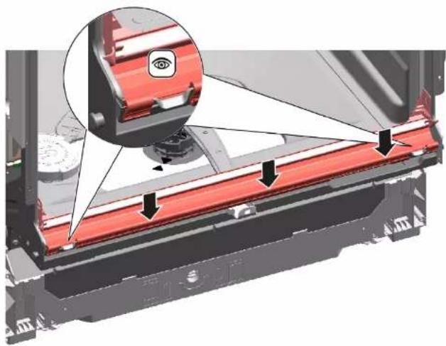
Mechanical assembly diagram showing a red component with arrows indicating motion or assembly, no visible text or symbols

3D diagram of a car door with red and black arrows indicating airflow or movement (no text or symbols)

  1. Odpnite kovinsko sponko na levi in desni strani.
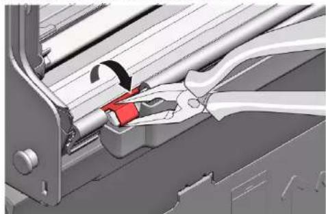
Mechanical assembly diagram showing a tool interacting with a rod and bracket (no text or symbols visible)

  1. Pritrdite tečaj vrat z vijaki.
  2. Namestite notranja vrata na tečaj vrat.
  3. Pritrdite notranja vrata z vijaki.

2.

Close-up of a red mechanical bracket with green cable and arrow indicating assembly (no text or symbols)

BOSCH SHI4HCS48E - Popravilo - 5

Popravilo

  1. Odklopite prelivni kanal.

3D mechanical assembly diagram showing a sliding mechanism with a red component (no text or symbols visible)

  1. Odstranite prelivni žleb.

3D mechanical assembly diagram showing internal components and a central hub (no text or symbols visible)

BOSCH SHI4HCS48E - Popravilo - 3

Popravilo

4.

BOSCH SHI4HCS48E - Popravilo - 1

V vogalih tesnilo ne sme biti nagubano ali razvlečeno. Konec tesnila je odrezan diagonalno in se skrije v sprednji spodnji del posode.

Namestite konec tesnila naravnost naprej pod notranjimi vrati. Tesnilo mora biti položeno ob robu posode čim dlje.

Pure technical line drawing of curved pipe or channel sections without any text, numbers, or symbols

BOSCH SHI4HCS48E - Popravilo - 3

Popravilo

4.21 Zamenjava EmotionLight

Diagram showing a device's internal structure with labeled parts and a tool inserted, likely illustrating a repair or disassembly process.

  1. Odstranite držalo v smeri navzgor (2).
  2. Povlecite vtič iz priključka (spodaj desno na sprednji strani aparata).
  1. Odstranite EmotionLight iz aparata.

4.21.2 Namestitev EmotionLight

  1. Vstavite držalo v okvir posode za izpiranje (1).
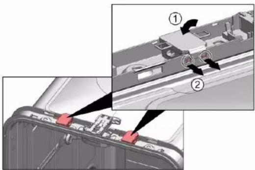
Technical diagram showing a device's internal components with numbered annotations indicating parts of the main body and parts of the rear panel.

BOSCH SHI4HCS48E - Namestitev EmotionLight - 2

Popravilo

  1. Poskrbite, da se zaskočna zatiča zaskočita (2).

3.

BOSCH SHI4HCS48E - Popravilo - 1

POZOR!

BOSCH SHI4HCS48E - POZOR! - 1

Popravilo

Close-up of a mechanical component with a red vertical stripe and black arrow indicating a cut or section (no text or symbols visible)

  1. Modul TimeLight povlecite navzgor in ven iz vodila (2).

4.22.2 Namestitev TimeLight

  1. Držalne elemente (1) upognite nazaj.

Technical diagram showing a red structural component with numbered annotations (1 and 2) indicating parts of a mechanical assembly.

  1. Modul TimeLight potisnite nazaj v vodilo (2).
  2. Priključite električni priključek.

BOSCH SHI4HCS48E - Namestitev TimeLight - 2

Popravilo

4.23 Zamenjava Gap illumination

Zahteva:

BOSCH SHI4HCS48E - Zahteva: - 1

Popravilo

4.23.2 Namestitev Gap illumination

  1. Pričvrstite ga tako, da zaslišite klik.
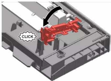
CLICK

  1. Enganchar el clip.

Mechanical diagram showing a lever mechanism with a curved arrow indicating rotational motion (no text or symbols)

BOSCH SHI4HCS48E - Namestitev Gap illumination - 3

Reparación

BOSCH SHI4HCS48E - Reparación - 1

Reparación

4.3 Sustituir el sistema varioDrawer

4.3.1 Extraer el sistema varioDrawer

Reparación

4.5.2 Montar los filtros

Fig. 1: Totalmente integrado
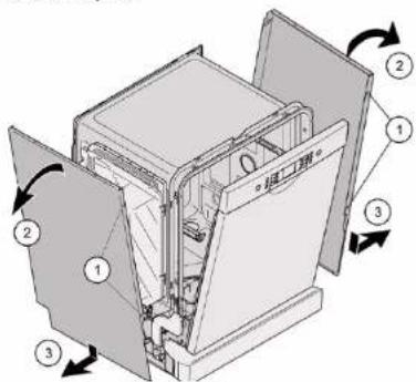
Technical diagram of a multi-chamber refrigerator with numbered components and directional arrows indicating internal flow or movement.

Fig. 2: Totalmente integrado
Technical diagram showing a mechanical assembly with numbered components and directional arrows indicating motion or assembly.

3.

Diagram showing a hand holding a screwdriver inserted into a device with a magnified inset highlighting the screw and its direction.

BOSCH SHI4HCS48E - Montar los filtros - 4

Reparación

  1. Retirar el panel.

4.14.2 Montar el zócalo

BOSCH SHI4HCS48E - Montar el zócalo - 1

Reparación

4.15 Sustituir la placa de enchufes de la base

Technical diagram showing a mechanical assembly with numbered components and directional arrows indicating motion or flow.

4.

Mechanical assembly diagram showing a red lever mechanism with labeled parts (1 and 2), no readable text or symbols present.

BOSCH SHI4HCS48E - Sustituir la placa de enchufes de la base - 3

Reparación

BOSCH SHI4HCS48E - Reparación - 1

Reparación

3D diagram of a vehicle door with red and black arrows indicating airflow or movement (no text or symbols)

BOSCH SHI4HCS48E - Reparación - 2

Reparación

4.17 Sustituir la puerta interior

Requisito:

4.18.2 Montar la bisagra de la puerta
Technical diagram showing mechanical assembly with numbered components and directional arrows indicating motion or movement.

2.

Close-up of a red mechanical bracket with green cable and arrow indicating assembly (no text or symbols)

Reparación

4.

Pure technical line drawing of curved structural elements without any text or symbols

BOSCH SHI4HCS48E - Reparación - 2

Reparación

4.21 Sustituir el sistema EmotionLight

Technical diagram showing a mechanical assembly with labeled parts and directional arrows indicating movement or assembly.

  1. Extraer la luz EmotionLight del aparato.

4.21.2 Montar el sistema EmotionLight

BOSCH SHI4HCS48E - Montar el sistema EmotionLight - 1

Reparación

Reparación

Close-up of a mechanical component with a red vertical stripe and black arrow indicating a section (no text or symbols visible)

Fig. 3: Cable plano

BOSCH SHI4HCS48E - Reparación - 2

Reparación

  1. Vik upp klämman.

Mechanical diagram showing a lever mechanism with a curved arrow indicating rotational motion (no text or symbols present)

2021-03-22_9001630792 Copyright BSH Hausgeräte GmbH Sida 915 av 989

BOSCH SHI4HCS48E - Reparación - 2

Reparation

BOSCH SHI4HCS48E - Reparation - 1

Reparation

4.3 Byta varioDrawer

4.3.1 Ta bort varioDrawer

BOSCH SHI4HCS48E - Ta bort varioDrawer - 1

Reparation

4.4.2 Montera sprutarm

4.5.2 Montera filter

3.

Diagram showing a hand inserting a screw into a device with a magnified view of the screw and its insertion direction.

4.11.2 Montera yttre lucka

Technical diagram of a refrigerator interior with labeled components and directional arrows indicating parts of the door.

BOSCH SHI4HCS48E - Montera yttre lucka - 2

Reparation

4.12 Byta manöverpanel

Diagram of a device interior with numbered components and colored wiring, likely illustrating a mechanical or electrical component layout.

4.14.2 Montera fotpanel

BOSCH SHI4HCS48E - Montera fotpanel - 1

Reparation

4.

Mechanical assembly diagram showing a red lever mechanism with labeled parts (1 and 2), no readable text or symbols present.

BOSCH SHI4HCS48E - Reparation - 2

Reparation

BOSCH SHI4HCS48E - Reparation - 1

Reparation

3D diagram of a car door frame with red and black arrows indicating directional movement (no text or symbols)

BOSCH SHI4HCS48E - Reparation - 2

Reparation

4.17 Byta inre lucka

Förutsättning:

2021-03-22_9001630792 Copyright BSH Hausgeräte GmbH Sida 938 av 989

2.

Close-up of a red mechanical bracket with green cable and arrow indicating connection (no text or symbols)

BOSCH SHI4HCS48E - Byta inre lucka - 2

Reparation

4.19 Byta luckans tätning (nedre)

Förutsättning:

BOSCH SHI4HCS48E - Förutsättning: - 1

Reparation

4.

Pure architectural or structural line drawing of curved and straight pipe sections without any text, numbers, or symbols

BOSCH SHI4HCS48E - Reparation - 2

Reparation

4.21 Byta EmotionLight

Diagram showing a device's internal components with numbered annotations indicating parts of the main body and parts of the device.

  1. Ta ut EmotionLight ur maskinen.

4.21.2 Montera EmotionLight

BOSCH SHI4HCS48E - Montera EmotionLight - 1

Reparation

BOSCH SHI4HCS48E - Reparation - 1

Reparation

Close-up of a mechanical component with a red vertical stripe and a black arrow pointing to a section (no visible text or symbols)

Bild 3: Flatkabel

  1. Sätt in kontakten.

BOSCH SHI4HCS48E - Reparation - 2

Reparation

4.22 Byta TimeLight

Technical diagram showing a mechanical assembly with numbered components and highlighted parts, likely illustrating a component assembly or assembly.

  1. Dra upp TimeLight-modulen ur styrningen (2).

4.22.2 Montera TimeLight

4.23 Byta Gap illumination

Förutsättning:
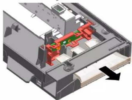
3D mechanical assembly diagram showing internal components with no visible text or symbols

BOSCH SHI4HCS48E - Förutsättning: - 2

Reparation

4.23.2 Montera Gap illumination

  1. Anslut ledningen till driftmodulen.

BOSCH SHI4HCS48E - Reparation - 1

Onarim

BOSCH SHI4HCS48E - Onarim - 1

Onarim

BOSCH SHI4HCS48E - Onarim - 1

Onarim

Resim 1: Tam ankastre
Technical diagram of a multi-chamber refrigerator with numbered components and directional arrows indicating internal flow.

Resim 2: Tam ankastre
Technical diagram showing a mechanical assembly with numbered components and directional arrows indicating motion or assembly.

  1. Yan paneli cihaza bastırın (2).
  2. Yan paneli vidalarla sabitleyin (3).

BOSCH SHI4HCS48E - Onarim - 3

Onarim

3.

Diagram showing a hand inserting a screw into a device with a magnified view of the screw and its insertion direction.

BOSCH SHI4HCS48E - Onarim - 2

Onarim

BOSCH SHI4HCS48E - Onarim - 1

Onarim

4.

Mechanical assembly diagram showing a red lever mechanism with labeled parts (1 and 2), no readable text or symbols present.

BOSCH SHI4HCS48E - Onarim - 2

Onarim

BOSCH SHI4HCS48E - Onarim - 1

Onarim

3D diagram of a mechanical component with red and black arrows indicating directional flow (no text or symbols)

BOSCH SHI4HCS48E - Onarim - 2

Onarim

2.

Close-up of a red mechanical bracket with green cable and arrow indicating connection (no text or symbols)

BOSCH SHI4HCS48E - Onarim - 2

Onarim

BOSCH SHI4HCS48E - Onarim - 1

Onarim

4.

Pure architectural or structural lines drawing without any text, numbers, or symbols

BOSCH SHI4HCS48E - Onarim - 2

Onarim

BOSCH SHI4HCS48E - Onarim - 1

Onarim

BOSCH SHI4HCS48E - Onarim - 1

Onarim

Close-up of a mechanical component with a red vertical stripe and black arrow indicating a cut or section (no text or symbols visible)

Resim 3: Düz kablo

  1. Fisi takın.

BOSCH SHI4HCS48E - Onarim - 2

Onarim

BOSCH SHI4HCS48E - Onarim - 1

Onarim

Table of contents Click a title to access it
Manual assistant
Powered by Anthropic
Waiting for your message
Product information

Brand : BOSCH

Model : SHI4HCS48E

Category : Dishwasher