NG16POE - Switch Tripp Lite - Free user manual and instructions
Find the device manual for free NG16POE Tripp Lite in PDF.
User questions about NG16POE Tripp Lite
0 question about this device. Answer the ones you know or ask your own.
Ask a new question about this device
Download the instructions for your Switch in PDF format for free! Find your manual NG16POE - Tripp Lite and take your electronic device back in hand. On this page are published all the documents necessary for the use of your device. NG16POE by Tripp Lite.
USER MANUAL NG16POE Tripp Lite
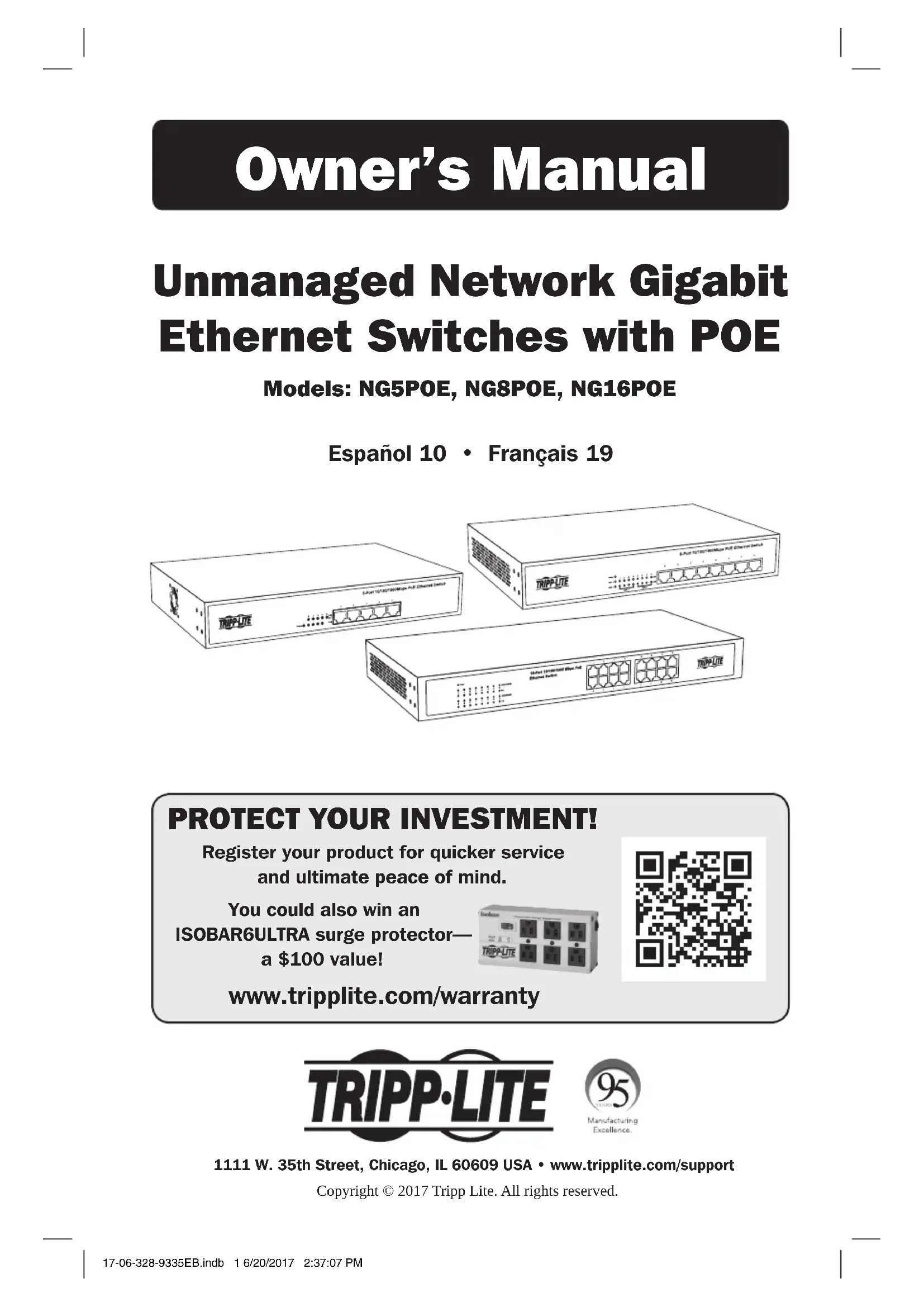
Unmanaged Network Gigabit Ethernet Switches with POE
Models: NG5POE, NG8POE, NG16POE
Español 10 • Français 19
text_image
3-Port TCP/800MHz PtE Channel Switch 3-Port TCP/800MHz PtE Channel Switch 3-Port TCP/800MHz PtE Channel Switch 3-Port TCP/800MHz PtE Channel SwitchPROTECT YOUR INVESTMENT!
Register your product for quicker service and ultimate peace of mind.
You could also win an ISOBAR6ULTRA surge protector— a \$100 value!

text_image
QR code image containing encoded data, no visible human-readable textwww.tripplite.com/warranty

text_image
TRIPP·LITE
1111 W. 35th Street, Chicago, IL 60609 USA • www.tripplite.com/support
Copyright © 2017 Tripp Lite. All rights reserved.
Important Safety Instructions

SAVE THESE INSTRUCTIONS!
This manual contains important instructions and warnings that should be followed during the installation, operation and storage of this Tripp Lite product. Failure to heed these warnings may affect your warranty.
Switch Location Warnings
- The switch is designed for indoor use only, in a controlled environment, away from excess moisture, temperature extremes, conductive contaminants, dust or direct sunlight.
- For best performance, maintain an indoor temperature between 32°F and 104°F (0°C and 40°C) with relative humidity between 10% and 90% (non-condensing).
- Leave adequate space around all sides of the switch for proper ventilation.
- Keep the switch away from high-frequency, strong-current devices (e.g., radio transmitting stations, transmitters and broadband amplifiers).
- Use electromagnetic shielding (if required).
- For rackmount configuration, ensure that both the rack and switch are properly grounded.
- If the switch is not rack mounted, securely place it on a sturdy, flat surface.
- The electrical outlets supplying power to the equipment should be installed near the equipment and easily accessible.
- Improper installation can cause product damage that is not covered by the warranty.
- Do not expose the network switch's connected networking cables to outdoor elements.
- Do not use this product near water (e.g., in a wet basement, or near a swimming pool).
- Use of this equipment in life support applications where failure of this equipment can reasonably be expected to cause the failure of the life support equipment or to significantly affect its safety or effectiveness is not recommended.
Important Safety Instructions
Switch Connection Warnings
- Keep the switch's input power off during installation.
- Use only the power adapter included with the switch.
- Make sure the power supply voltage matches the specifications indicated on the switch.
- Connect the switch to an outlet that is in accordance with your local building codes and that is adequately protected against excess currents, short circuits and earth faults.
- Do not connect the switch to an ungrounded outlet or to extension cords or adapters that eliminate the connection to ground.
- Do not drill into or attempt to open any part of the switch housing. There are no user-serviceable parts inside.
- Do not attempt to modify the switch, including the input plugs and power cables.
- Do not attempt to use the switch if any part of it becomes damaged.
- Make sure network cables are properly seated. A clicking sound will be made when a cable is installed correctly.
- If the power adapter is damaged, do not attempt to connect the switch. Contact a Tripp Lite Service Representative for assistance.
- Never attempt to install or use the switch during a thunderstorm.
Package Includes
- NG5POE, NG8POE or NG16POE Unmanaged Network Gigabit Ethernet Switch with POE
- Detachable Power Cord
- Mounting Brackets (2)
- Screws (8)
- Rubber feet (4)
- Owner's Manual
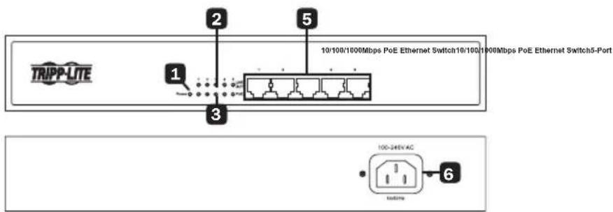
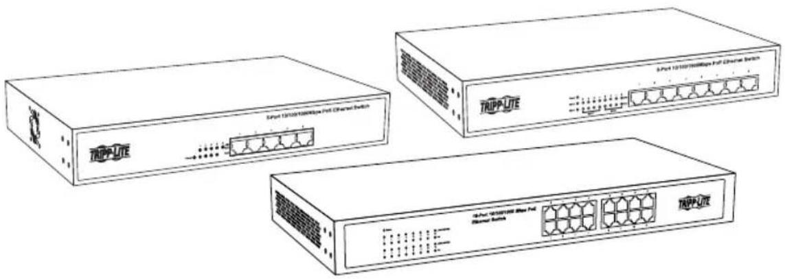
Product Features
NG5POE
text_image
TRIPP-LITE 10/100/1000Mbps PoE Ethernet Switch10/100/1000Mbps PoE Ethernet Switch5-Port 1 2 3 5 6 100-346V AC systemaNG8POE

text_image
TRIPP-LITE 1 2 3 4 5 8-Port 10/106/100Mbps PoE Ethernet Switch 100-240V AC 04/Wang 6NG16POE
text_image
16-Port 10/100/1000 Mbps PoE Ethernet Switch TRIPP-LITE 2 3 5 6 100-240V AC 50/80HzProduct Features
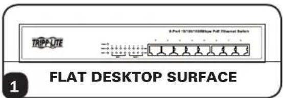
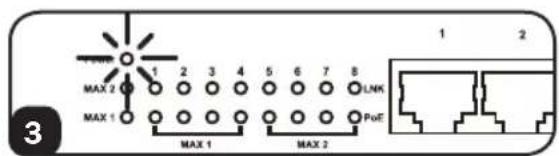
1 Power ON/OFF LED: An LED illuminates to indicate the switch is receiving power.
2 Ethernet Port LEDs: Each LED will illuminate when a connection is present and blink when the port is active.
Notes:
- NG5POE only: PoE (Power over Ethernet) is limited to ports 1-4. LEDs illuminate green for all network connection speeds.
- NG8POE and NG16POE only: LEDs illuminate orange for 10/100 Mbps network connections and green for 1000 Mbps network connections.
3 PoE LEDs: The corresponding PoE LEDs illuminate green when an active PoE device connection is detected.
4 PoE Max LEDs (NG8POE only): These two LEDs illuminate to indicate when the maximum power budget of each port group has been reached (MAX 1=Ports 1-4, MAX 2=Ports 5-8). They will blink when the maximum power budget for the port group has been exceeded. They turn OFF when the maximum power budget is less than the available power offered by each port group.
5 Gigabit Ethernet Ports: Each of the RJ45 twisted-pair ports support auto-negotiable 10/100/1000 Mbps and auto MDI/MDIX cross-over detection functions for true “plug and play” capability. Each port can supply up to 30 watts of PoE power per port over existing network cables to attached devices like VoIP phones, wireless access points and surveillance cameras.
6 AC Input: This 100-240V 50/60 Hz C14 inlet accepts the included AC power cord or any country-specific AC power cord supplied by the user.
PoE Power
| Model PoE Power per Port Total PoE Power (switch) | ||
| NG5POE* | Up to 26W 75W | |
| NG8POE | Up to 30W 140W** | |
| NG16POE | Up to 30W 230W | |
* PoE power available on ports 1-4 only.
** Total PoE power budget split into two 70W PoE port groups.
Quick Installation
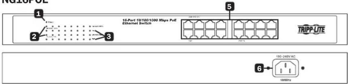
Desktop Installation
1 Attach the four included rubber feet to the bottom of the unit. Place the switch on a flat desktop surface. Inspect and install the power adapter to a proper AC power source.
2 Connect the power supply to the switch. The Power LED will illuminate when the switch turns on.
3 Ensure adequate ventilation around the switch for proper cooling.
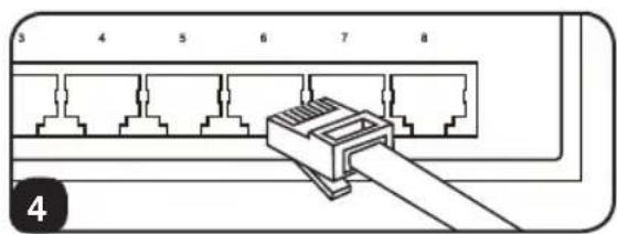
4 Connect the network cables to the network switch.
text_image
TRIPP-LTE 8-Port 15/10/1000bps Full Channel Switch FLAT DESKTOP SURFACE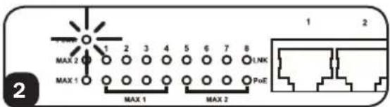
text_image
MAX 2 MAX 1 1 2 3 4 5 6 7 8 1,NK PoE MAX 1 MAX 2 1 2
text_image
Diagram showing bidirectional data flow between a network device with labeled ports and arrows indicating data flow direction.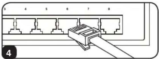
text_image
3 4 5 6 7 8 4Quick Installation
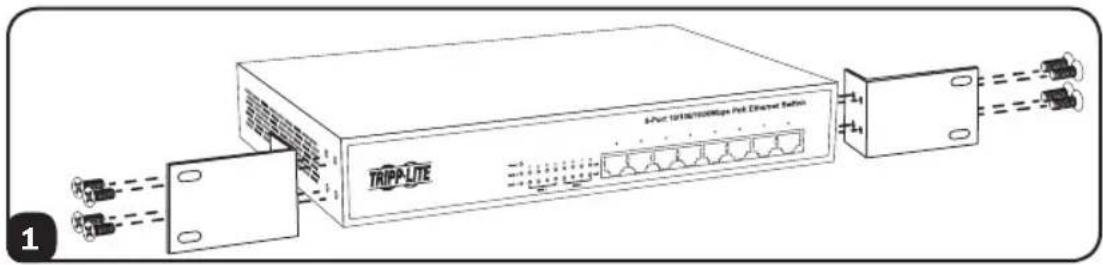
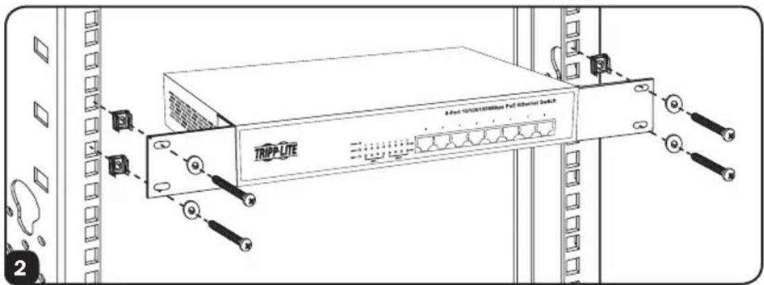
1U Rackmount Installation
The NG8POE is shown in the installation diagram. The other two models can also be rack mounted.
1 Attach the mounting brackets to each side of the switch with the included screws. Be sure the mounting bracket “ears” are facing forward.
text_image
TrippLite Multi-Linkless/MIps Net Diameter Section2 Mount the switch with user-supplied rackmount hardware.
Note: The user must determine the fitness of the rackmount hardware to hold the unit in the rack before installation.
text_image
TRIPP LITE A Fort 10/08/2008/Max Pac Channel Switch3 Connect the switch to a properly grounded outlet. The Power LED will illuminate when the switch turns on.
text_image
MAX 2 MAX 1 1 2 3 4 5 6 7 8 LNK PoE MAX 1 MAX 2 1 2 34 Connect network cables to the network switch.
text_image
3 4 5 6 7 8 4Warranty & Product Registration
5-Year Limited Warranty
TRIPP LITE warrants its products to be free from defects in materials and workmanship for a period of five (5) years from the date of initial purchase. TRIPP LITE's obligation under this warranty is limited to repairing or replacing (at its sole option) any such defective products. To obtain service under this warranty, you must obtain a Returned Material Authorization (RMA) number from TRIPP LITE or an authorized TRIPP LITE service center. Products must be returned to TRIPP LITE or an authorized TRIPP LITE service center with transportation charges prepaid and must be accompanied by a brief description of the problem encountered and proof of date and place of purchase. This warranty does not apply to equipment which has been damaged by accident, negligence or misapplication or has been altered or modified in any way.
EXCEPT AS PROVIDED HEREIN, TRIPP LITE MAKES NO WARRANTIES, EXPRESS OR IMPLIED, INCLUDING WARRANTIES OF MERCHANTABILITY AND FITNESS FOR A PARTICULAR PURPOSE. Some states do not permit limitation or exclusion of implied warranties; therefore, the aforesaid limitation(s) or exclusion(s) may not apply to the purchaser.
EXCEPT AS PROVIDED ABOVE, IN NO EVENT WILL TRIPP LITE BE LIABLE FOR DIRECT, INDIRECT, SPECIAL, INCIDENTAL OR CONSEQUENTIAL DAMAGES ARISING OUT OF THE USE OF THIS PRODUCT, EVEN IF ADVISED OF THE POSSIBILITY OF SUCH DAMAGE. Specifically, TRIPP LITE is not liable for any costs, such as lost profits or revenue, loss of equipment, loss of use of equipment, loss of software, loss of data, costs of substitutes, claims by third parties, or otherwise.
PRODUCT REGISTRATION
Visit www.tripplite.com/warranty today to register your new Tripp Lite product. You'll be automatically entered into a drawing for a chance to win a FREE Tripp Lite product!*
* No purchase necessary. Void where prohibited. Some restrictions apply. See website for details.
Regulatory Compliance Identification Numbers
For the purpose of regulatory compliance certifications and identification, your Tripp Lite product has been assigned a unique series number. The series number can be found on the product nameplate label, along with all required approval markings and information. When requesting compliance information for this product, always refer to the series number. The series number should not be confused with the marketing name or model number of the product.
Warranty & Product Registration
FCC Notice, Class A (NG16POE)
This device complies with part 15 of the FCC Rules. Operation is subject to the following two conditions: (1) This device may not cause harmful interference, and (2) this device must accept any interference received, including interference that may cause undesired operation.
Note: This equipment has been tested and found to comply with the limits for a Class A digital device, pursuant to part 15 of the FCC Rules. These limits are designed to provide reasonable protection against harmful interference when the equipment is operated in a commercial environment. This equipment generates, uses, and can radiate radio frequency energy and, if not installed and used in accordance with the instruction manual, may cause harmful interference to radio communications. Operation of this equipment in a residential area is likely to cause harmful interference in which case the user will be required to correct the interference at his own expense. The user must use shielded cables and connectors with this equipment. Any changes or modifications to this equipment not expressly approved by Tripp Lite could void the user's authority to operate this equipment. CAN ICES-3 (A)/NMB-3(A)
FCC Notice, Class B (NG5POE & NG8POE)
This device complies with part 15 of the FCC Rules. Operation is subject to the following two conditions: (1) This device may not cause harmful interference, and (2) this device must accept any interference received, including interference that may cause undesired operation.
Note: This equipment has been tested and found to comply with the limits for a Class B digital device, pursuant to part 15 of the FCC Rules. These limits are designed to provide reasonable protection against harmful interference in a residential installation. This equipment generates, uses and can radiate radio frequency energy and, if not installed and used in accordance with the instructions, may cause harmful interference to radio communications. However, there is no guarantee that interference will not occur in a particular installation. If this equipment does cause harmful interference to radio or television reception, which can be determined by turning the equipment off and on, the user is encouraged to try to correct the interference by one or more of the following measures:
- Reorient or relocate the receiving antenna.
- Increase the separation between the equipment and receiver.
- Connect the equipment into an outlet on a circuit different from that to which the receiver is connected.
- Consult the dealer or an experienced radio/TV technician for help.
Any changes or modifications to this equipment not expressly approved by Tripp Lite could void the user's authority to operate this equipment.
CAN ICES-3 (B)/NMB-3(B)
WEEE Compliance Information for Tripp Lite Customers and Recyclers (European Union)

Under the Waste Electrical and Electronic Equipment (WEEE) Directive and implementing regulations, when customers buy new electrical and electronic equipment from Tripp Lite they are entitled to:
- Send old equipment for recycling on a one-for-one, like-for-like basis (this varies depending on the country)
- Send the new equipment back for recycling when this ultimately becomes waste
Tripp Lite has a policy of continuous improvement. Specifications are subject to change without notice.

text_image
TRIPP·LITE
1111 W. 35th Street, Chicago, IL 60609 USA • www.tripplite.com/support
Modelos: NG5POE, NG8POE, NG16POE
English 1 • Français 19
text_image
S-Port 120/100/100MHz Full Channel Switch S-Port 120/100/100MHz Full Channel Switch S-Port 120/100/100MHz Full Channel Switch S-Port 120/100/100MHz Full Channel Switch S-Port 120/100/100MHz Full Channel Switch S-Port 120/100/100MHz Full Channel Switch
text_image
TRIPP·LITE
1111 W. 35th Street, Chicago, IL 60609 EE. UU. • www.tripplite.com/support
text_image
Diagram showing bidirectional data flow between a network switch device and a server, with arrows indicating direction of data transmission.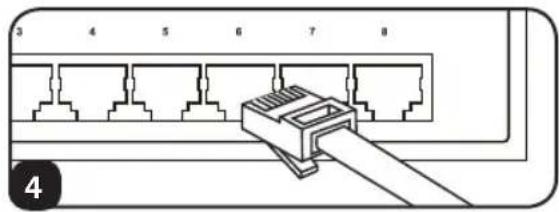
natural_image
Diagram of a network switch connector with numbered pins (3–8) and a cable, no text or symbols present.Instalación Rápida
natural_image
Diagram of a network switch connector with 8 ports and a cable, no text or symbols presentGarantía
1111 W. 35th Street, Chicago, IL 60609 USA • www.tripplite.com/support
CONSERVEZ CES INSTRUCTIONS!
text_image
Diagram showing bidirectional data flow between a network device labeled 'APC' with arrows indicating direction.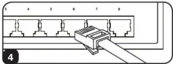
natural_image
Diagram of a network switch connector with numbered pins (3 to 8) and a cable, no text or symbols present.Installation rapide
1111 W. 35th Street, Chicago, IL 60609 USA • www.tripplite.com/support