
T015POE - Computer and peripheral cables Tripp Lite - Free user manual and instructions
Find the device manual for free T015POE Tripp Lite in PDF.
| Product Type | Power over Ethernet (PoE) Cable Tester |
| Brand | Tripp Lite |
| Model | T015-POE |
| Power Supply | 3 AAA 1.5 V batteries (included) |
| Display | LCD with backlight, 128 x 64 mm |
| Main Functions | PoE test (standard/non-standard), continuity test, loop test, DC power test, wiremap test |
| Continuity test range | 600 m (1,968 ft) max |
| Supported Cable Types | UTP, STP (8 or 9 conductors) |
| PoE voltage test range | 5 V to 60 V DC |
| PoE power test range | 0 W to 18 W |
| DC voltage test range | 0 V to 60 V DC |
| DC current test range | 0 A to 3 A |
| DC power test range | 0 W to 180 W |
| PoE standards detected | IEEE 802.3af/at (standard and non-standard) |
| Loop test | Compatible with 10/100/1000 Mbps switches |
| Input voltage protection | 48 V DC, 5 mA |
| Max working current | ≤ 80 mA |
| Remote Unit | No batteries needed, RJ45 port, wiremap function |
| Package Contents | Transmitter, remote unit, test cable, 3 AAA batteries, carrying case, manual |
| Warranty | 2 years |
Frequently Asked Questions - T015POE Tripp Lite
User questions about T015POE Tripp Lite
0 question about this device. Answer the ones you know or ask your own.
Ask a new question about this device
Download the instructions for your Computer and peripheral cables in PDF format for free! Find your manual T015POE - Tripp Lite and take your electronic device back in hand. On this page are published all the documents necessary for the use of your device. T015POE by Tripp Lite.
USER MANUAL T015POE Tripp Lite
Power over Ethernet Tester
Model: T015-POE
Español 20 • Français 39 • Русский 58
WARRANTY REGISTRATION
Register your product today and be automatically entered to win an ISOBAR surge protector in our monthly drawing!
tripplite.com/warranty


Manufacturing Excellence.
1111 W. 35th Street, Chicago, IL 60609 USA • tripplite.com/support
Copyright © 2019 Tripp Lite. All rights reserved.
General Safety Instructions
- The emitter unit is powered by three AAA 1.5V dry-cell batteries. The remote unit does not need supplied power.
- Use only batteries that meet the above specifications to avoid damaging the tester.
- Do not place the tester in a location that is dusty, humid or above 104^ F (40°C).
- Do not disassemble the tester. There are no user-serviceable parts.
- When the tester will not be used for an extended period, remove the batteries to prevent battery leakage and damage to the unit.
- Do not use the tester to detect live power lines (such as 220V power supply lines); damage to the unit or personal injury may occur.
- Do not perform operations on communications lines during thunderstorms in order to prevent personal injury from lightning strikes.
Package Contents
- Emitter Unit
- Remote Unit
- Cable Lead
- AAA Batteries (3x)
- Carrying Case
- Owner's Manual
Typical Applications
- Test the information of standard/non-standard PoE devices, such as voltage, polarity, midspan or endspan
- Identify the power-supplying equipment (PSE) type, 802.3af or 802.3at standard
- Test the real-time power consumed by Power Delivery (PD) devices in PoE power supply systems
- Test the open, short and cross status in the network cable
- Test the power consumed by DC applications
• Test the loopback function of a switch
Overview
The T015-POE Power over Ethernet Tester consists of two parts: an emitter and a remote. It has functions such as standard and non-standard PoE equipment detection, PoE power online test, network cable continuity test, DC power test, switch loop-back test and other functions. It is a practical tool for technical personnel to use during installation and maintenance of security monitoring equipment, communications wiring, integrated wiring and other weak-current systems.
flowchart
graph TD
    A["A"] --> D["Central Device"]
    B["B"] --> D
    C["C"] --> D
    D --> E["E"]
    D --> F["F"]
    D --> I["I"]
    D --> K["K"]
    D --> J["J"]
    D --> L["L"]
4
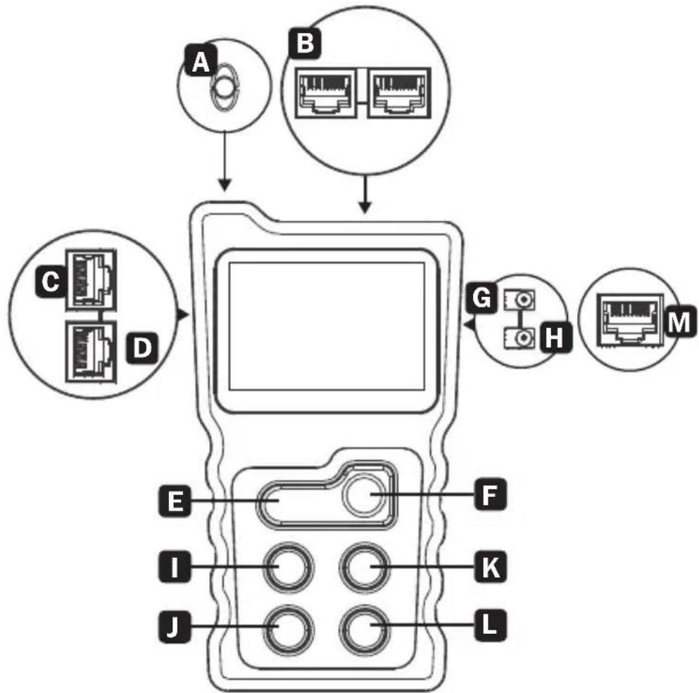
Overview
A Light
B PoE Test Ports
C Loopback Test Port
D Wire Mapping Test Port
E Light On/Off Key
F Power On/Off Key
G DC Power Input Port
H DC Power Output Port
I Scroll Left Key
J Return Key
K Scroll Right Key
L OK Key
M Cable Continuity Test Port
Specifications
| Emitter Indicator LCD with Backlight, 128 x 64 mm | ||
| Continuity Function | Cable Types STP UTP | |
| Max. Testing Range | 1968 ft. (600 m) | |
| Wire Mapping | Emitter + Remote | |
| Emitter + Switch/Router | ||
| PoE Function | Test Range | DC 5V-60V POE Switch |
| Standard Identify | 802.3af/at(Standard/Non-Standard) | |
| Test Range Power O | W-18W | |
| Power Function | Voltage Test Range | DC 0V-60V |
| Current Test Range | OA-3A | |
| Power Test Range O | A-180W | |
| Input Voltage Protection DC48V 5mA | ||
| Max. Working Current ≤80mA | ||
| Loopback | Compatible with 10M, 100M, 1000M Switch | |
| Power Supply AAA Batteries, 3x | ||
| Remote Specifications | ||
| Port RJ45 | ||
| Function Wire Mapping for Network Cables | ||
| Input Voltage Protection DC48V 5mA | ||
Product Usage
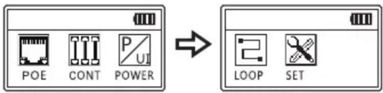
Main Menu
- PoE – PoE switch test and PoE power test
- CONT – Test open, short and cross, etc.
- POWER – Test voltage and current between the power adapter and the powered device, as well as calculate the power consumed by the powered device
- LOOP – Test whether the loopback of the network cable that is connected to the switch is working properly
- SET – Set up language, backlight time, auto power-off time, contrast and versions
PoE Test Function
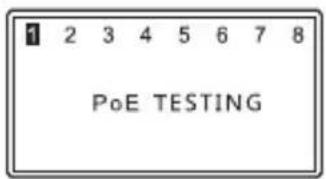
PoE Switch Test
Connect a LAN cable between the PoE switch and the PoE port of the emitter. Once the connection is made, a fluctuating voltage value will display on the screen. Press “OK” to starting testing. The result will display at the screen.
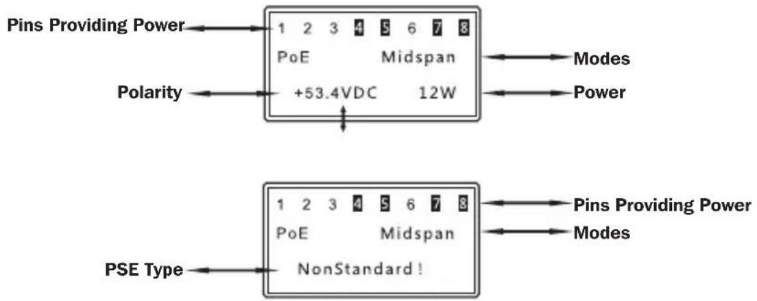
Standard PoE Equipment
If the tested PoE switch is standard, the testing result will display as the following image.

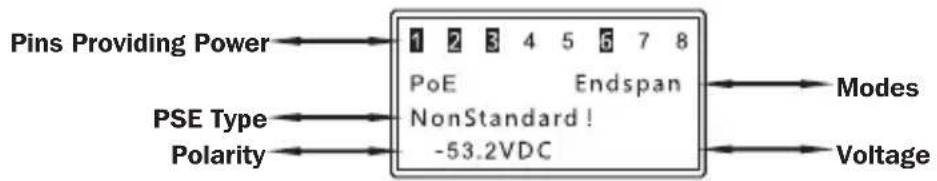
Non-Standard PoE Equipment
If the tested PoE switch is non-standard, the testing result will display the following image.
PoE Test Function
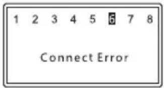
Error Connection
If the test result displays “Connect Error”, the connection is not normal or other PoE devices are connected to the circuit. After reconnecting correctly, perform the test again.
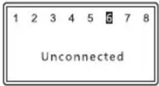
No Connection
If the test result displays Unconnected, the PoE equipment is not detected.
PoE Test Function
PoE Power Test
In the PoE power test, a PoE power supply device and a PoE powered device (such as a PoE switch and a PoE camera) need to be connected to emitter's PoE port.
After the correct connection is made, a fluctuating voltage value will display at the screen. A few seconds later, it will automatically enter the power testing interface. The display information appears like the following image.
When the screen displays PoE Power, press the “OK” key to identify the type of PSE. If the “Non-Standard” message appears, the PoE power supply device does not comply with the PoE standard. If no new message appears, it indicates the PoE power supply device complies with the PoE standard. (PoE power is the power currently consumed by the PoE powered device). Use the PoE switch test function to test the switch separately.
PoE Test Function
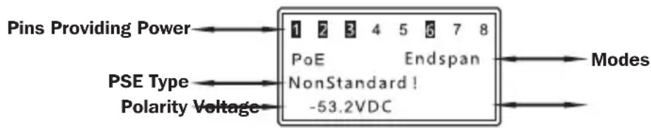
Special Circumstances
If a PoE device is connected to the emitter and enters the power display interface directly as in the following first image, the PoE device is a non-standard type. Under this condition, press the "OK" key to see the screen prompt message as "Non-Standard" as in the second image.
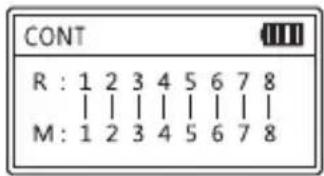
Wire Mapping Test
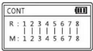
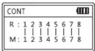
This test is to check cable short, open and cross status. The tested cable can be UTP 8-core network cable or STP 9-core network cable. The following images show good connection status.
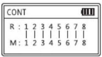
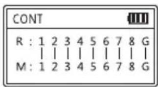
8 Pins 9 Pins
If there is a short circuit, or short and cross circuit, open status exists together, the device displays only short circuit, with no other status displayed.
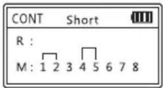
1 / 2 and 4 / 5 pair is short-circuited, respectively
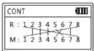
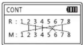
Other Status Displays:
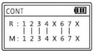
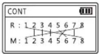
Pins 5 & 8 are broken Pins 5 & 6 are crossed; Good condition Pins 1 & 8 are crossed
Wire Mapping Test
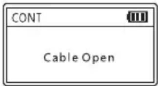
If the test result is “Cable Open”, check for these conditions:
- The cable is open
- The cable is not connected to the emitter
- The cable to the remote unit has been disconnected
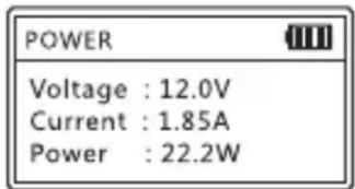
Power Test Function
This test is to check voltage, current and power between the power adapter and the powered device. Connect the power adapter to device and choose “Power” at the main menu. The results will display immediately.
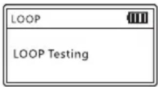
Loop-Back Test
This test checks whether the loopback of the network cable that is connected to the switch is functioning properly.
Connect the switch port to the loop-back port of the emitter with a network cable. If the indicator is on, the loop is proper. If the indicator is off, problems exist within the loop.
Lighting Function
Press the Light key to turn on or turn off the light.
Settings
Language Settings
English is the only language setting available.
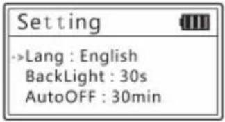
Backlight Settings
Adjust the backlight time among 15 seconds, 30 seconds, 60 seconds, long light and off.

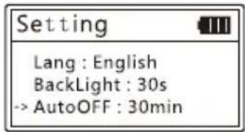
Auto-Off Time
Adjust the backlight time among 15 minutes, 30 minutes, 1 hour, OFF.
Settings
Contrast Settings
Press the left and right keys to adjust the contrast until the desired contrast is displayed.
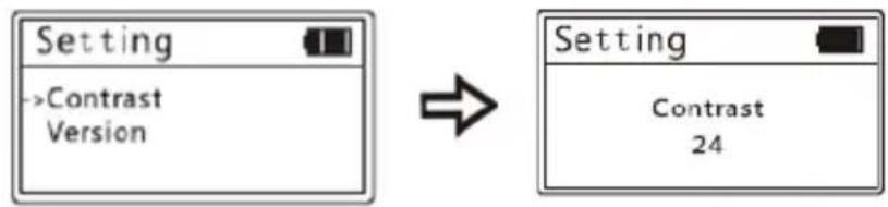
flowchart
graph LR
    A["Setting"] --> B["->Contrast Version"]
    B --> C["Setting"]
    C --> D["Contrast 24"]
Version Information
Displays the current version information of software and hardware.
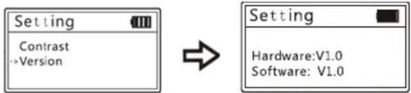
flowchart
graph LR
    A["Setting"] --> B["Contrast"]
    B --> C["->Version"]
    D["Setting"] --> E["Hardware: V1.0"]
    D --> F["Software: V1.0"]
Warranty
2-YEAR LIMITED WARRANTY
TRIPP LITE warrants its products to be free from defects in materials and workmanship for a period of two (2) years from the date of initial purchase. TRIPP LITE's obligation under this warranty is limited to repairing or replacing (at its sole option) any such defective products. To obtain service under this warranty, you must obtain a Returned Material Authorization (RMA) number from TRIPP LITE or an authorized TRIPP LITE service center. Products must be returned to TRIPP LITE or an authorized TRIPP LITE service center with transportation charges prepaid and must be accompanied by a brief description of the problem encountered and proof of date and place of purchase. This warranty does not apply to equipment, which has been damaged by accident, negligence or misapplication or has been altered or modified in any way.
EXCEPT AS PROVIDED HEREIN, TRIPP LITE MAKES NO WARRANTIES, EXPRESS OR IMPLIED, INCLUDING WARRANTIES OF MERCHANTABILITY AND FITNESS FOR A PARTICULAR PURPOSE.
Some states do not permit limitation or exclusion of implied warranties; therefore, the aforesaid limitation(s) or exclusion(s) may not apply to the purchaser.
EXCEPT AS PROVIDED ABOVE, IN NO EVENT WILL TRIPP LITE BE LIABLE FOR DIRECT, INDIRECT, SPECIAL, INCIDENTAL OR CONSEQUENTIAL DAMAGES ARISING OUT OF THE USE OF THIS PRODUCT, EVEN IF ADVISED OF THE POSSIBILITY OF SUCH DAMAGE. Specifically,
TRIPP LITE is not liable for any costs, such as lost profits or revenue, loss of equipment, loss of use of equipment, loss of software, loss of data, costs of substitutes, claims by third parties, or otherwise.
Warranty
Product Registration
Visit tripplite.com/warranty today to register your new Tripp Lite product. You'll be automatically entered into a drawing for a chance to win a FREE Tripp Lite product!*
* No purchase necessary. Void where prohibited. Some restrictions apply. See website for details.
FCC Notice, Class B
This device complies with part 15 of the FCC Rules. Operation is subject to the following two conditions: (1) This device may not cause harmful interference, and (2) this device must accept any interference received, including interference that may cause undesired operation.
Note: This equipment has been tested and found to comply with the limits for a Class B digital device, pursuant to part 15 of the FCC Rules. These limits are designed to provide reasonable protection against harmful interference in a residential installation. This equipment generates, uses and can radiate radio frequency energy and, if not installed and used in accordance with the instructions, may cause harmful interference to radio communications. However, there is no guarantee that interference will not occur in a particular installation. If this equipment does cause harmful interference to radio or television reception, which can be determined by turning the equipment off and on, the user is encouraged to try to correct the interference by one or more of the following measures:
• Reorient or relocate the receiving antenna.
- Increase the separation between the equipment and receiver.
- Connect the equipment into an outlet on a circuit different from that to which the receiver is connected.
- Consult the dealer or an experienced radio/TV technician for help.
Any changes or modifications to this equipment not expressly approved by Tripp Lite could void the user's authority to operate this equipment.
Warranty
WEEE Compliance Information for Tripp Lite Customers and Recyclers (European Union)

Under the Waste Electrical and Electronic Equipment (WEEE)
Directive and implementing regulations, when customers buy new electrical and electronic equipment from Tripp Lite they are entitled to:
- Send old equipment for recycling on a one-on-one, like-for-like basis (this varies depending on the country)
- Send the new equipment back for recycling when this ultimately becomes waste.
Use of this equipment in life support applications where failure of this equipment can reasonably be expected to cause the failure of life support equipment or to significantly affect its safety or effectiveness is not recommended.


Manufacturing Excellence.
1111 W. 35th Street, Chicago, IL 60609 USA • tripplite.com/support
19-10-184 93-3B7C_RevA
Parámetros

Manufacturing Excellence.
1111 W. 35th Street, Chicago, IL 60609, EE. UU. • tripplite.com/support
19-10-184 93-3B7C_RevA
1111 W. 35th Street, Chicago, IL 60609 USA • tripplite.com/support
Réglages
Garantie
GARANTIE LIMITÉE DE 2 ANS
1111 W. 35th Street, Chicago, IL 60609 USA • tripplite.com/support
19-10-184 93-3B7C_RevA
Manufacturing Excellence.
1111 W. 35th Street, Chicago, IL 60609 USA • tripplite.com/support
Функция подсветки
Настройки подсветки
Настройки

Manufacturing Excellence.
1111 W. 35th Street, Chicago, IL 60609 USA • tripplite.com/support


- Power over Ethernet Tester
- WARRANTY REGISTRATION
- General Safety Instructions
- Package Contents
- Typical Applications
- Overview
- Specifications
- Product Usage
- Main Menu
- PoE Test Function
- PoE Switch Test
- Standard PoE Equipment
- Non-Standard PoE Equipment
- Error Connection
- No Connection
- PoE Power Test
- Special Circumstances
- Wire Mapping Test
- Power Test Function
- Loop-Back Test
- Lighting Function
- Settings
- Language Settings
- Backlight Settings
- Auto-Off Time
- Contrast Settings
- Version Information
- Warranty
- 2-YEAR LIMITED WARRANTY
- Product Registration
- FCC Notice, Class B
- WEEE Compliance Information for Tripp Lite Customers and Recyclers (European Union)
- Parámetros
- Réglages
- Garantie
- GARANTIE LIMITÉE DE 2 ANS
- Функция подсветки
- Настройки подсветки
- Настройки
Brand : Tripp Lite
Model : T015POE
Category : Computer and peripheral cables