
PDUMH15HVATNET - Power strip Tripp Lite - Free user manual and instructions
Find the device manual for free PDUMH15HVATNET Tripp Lite in PDF.

| Product Type | Rackmount PDU (Power Distribution Unit) 1U, Switched and Digital Meter, Automatic Transfer Switch (ATS) |
| Brand | Tripp Lite |
| Model | PDUMH15HVATNET |
| Dimensions (W x D x H) | Approx. 44.5 x 43.2 x 4.4 cm (19 inch 1U format) |
| Weight | Approx. 5 kg |
| Power Supply | Dual AC input: primary and secondary, IEC C14 (removable cords included). Selectable voltage: 200-208 V (LO) or 220-240 V (HI). Rated current: 15 A max. per input |
| Outlets | 8 x NEMA 5-15R, 2 x NEMA 5-15/20R, 4 x IEC-320-C13 (all individually switchable via software) |
| Main Functions | Automatic Transfer Switch (ATS) between inputs, remote monitoring and control via Web/SNMP/Telnet, programmable outlet power sequencing, digital display of total current |
| Network Management | RJ45 Ethernet port (10/100 Mbps), SNMP protocol, PowerAlert Web interface, dynamic IP (DHCP) or static, configuration via serial terminal |
| Safety | Compliant with CISPR 32 Class A, overcurrent protection, mandatory grounding, installation by qualified technician only, do not use in explosive atmosphere |
| Maintenance and Cleaning | No user-serviceable parts; clean with a dry non-abrasive cloth; do not expose to moisture or dust |
| Spare Parts / Included Accessories | 2 C13-C14 interconnection cords, plug locking devices, cable retention tray, mini-DIN to DB9 serial cable for configuration |
| Warranty | 2-year limited (parts and labor) |
| Operating Temperature | 0 to 50 °C |
| Visual Indicators | Digital ammeter, LED for each outlet (power present), LED for active input source, network status LED (Link/Status) |
Frequently Asked Questions - PDUMH15HVATNET Tripp Lite
User questions about PDUMH15HVATNET Tripp Lite
0 question about this device. Answer the ones you know or ask your own.
Ask a new question about this device
Download the instructions for your Power strip in PDF format for free! Find your manual PDUMH15HVATNET - Tripp Lite and take your electronic device back in hand. On this page are published all the documents necessary for the use of your device. PDUMH15HVATNET by Tripp Lite.
USER MANUAL PDUMH15HVATNET Tripp Lite
Switched/Metered Rack PDU with Automatic Transfer Switch
Models: PDUMH15AT, PDUMH15ATNET, PDUMH15HVAT, PDUMH15HVATNET, PDUMH20AT, PDUMH20ATNET, PDUMH20HVAT, PDUMH20HVATNET
Series Number: AGAC7625
-
Important Safety Instructions 2
-
Installation 3
2.1 Mounting the PDU 3
2.2 Connecting the PDU 3
2.3 Networking the PDU 6
2.4 Test and Configure 9
-
Features 11
-
Configuration and Operation 14
4.1 Automatic Transfer Switch 14
4.2 Remote Monitoring and Control 15
-
Technical Support 16
-
Warranty and Product Registration 16
Espanol 17
Français 33
PROTECT YOUR INVESTMENT!
Register your product for quicker service and ultimate peace of mind.
You could also win an ISOBAR6ULTRA surge protector—a $100 value!

www.triplite.com/warranty
TRIPP·LITE

Manufacturing Excellence.
1111 W. 35th Street, Chicago, IL 60609 USA • www.triplite.com/support
Copyright © 2016 Tripp Lite. All rights reserved.
1. Important Safety Instructions
SAVE THESE INSTRUCTIONS
-
This manual contains instructions and warnings that should be followed during the installation, operation, and storage of this product. Failure to heed these instructions and warnings may affect the product warranty.
-
Warning: This equipment is compliant with Class A of CISPR 32. In a residential environment, this equipment may cause radio interference.

- The PDU provides the convenience of multiple outlets, but DOES NOT provide surge or line noise protection for connected equipment.
- The PDU is designed for indoor use only, in a controlled environment, away from excess moisture, temperature extremes, conductive contaminants, dust or direct sunlight.
- Keep indoor ambient temperature between 32^ and 122^ ( 0^ and 50^ ).
- The PDU must be installed by a qualified technician only.
- Do not attempt to mount the PDU to an insecure or unstable surface.
- Install in accordance with National Electrical Code standards. Be sure to use the proper overcurrent protection for the installation, in accordance with the plug/equipment rating.
- Connect the PDU to an outlet that is in accordance with your local building codes and that is adequately protected against excess currents, short circuits and earth faults.
- The electrical outlets supplying power to the equipment should be installed near the equipment and easily accessible.
- Do not connect the PDU to an ungrounded outlet or to extension cords or adapters that eliminate the connection to ground.
- Be sure to provide a local disconnect device on any models that are permanently installed without a plug that is easily accessible.
- Never attempt to install electrical equipment during a thunderstorm.
- Individual equipment connected to the PDU should not draw more current than the individual PDU's outlet's rating.
- The total load connected to the PDU must not exceed the maximum load rating for the PDU.
- Do not attempt to modify the PDU, input plugs or power cables.
- Do not drill into or attempt to open any part of the PDU housing. There are no user-serviceable parts inside.
- Do not attempt to use the PDU if any part of it becomes damaged.
- Use of this equipment in life support applications where failure of this equipment can reasonably be expected to cause the failure of the life support equipment or to significantly affect its safety or effectiveness is not recommended. Do not use this equipment in the presence of a flammable anesthetic mixture with air, oxygen or nitrous oxide.
2. Installation
2.1 Mounting the PDU
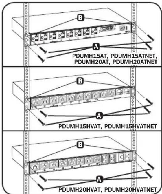
The PDU supports 1U Rack configurations.
Note: The user must determine the fitness of hardware and procedures before mounting. The PDU and included hardware are designed for common rack and rack enclosure types and may not be appropriate for all applications. Exact mounting configurations may vary.
1U Rack Mounting: Attach the PDU to the rack by inserting four user-supplied screws A through the PDU mounting brackets B and into the mounting holes of the rack rail as shown.
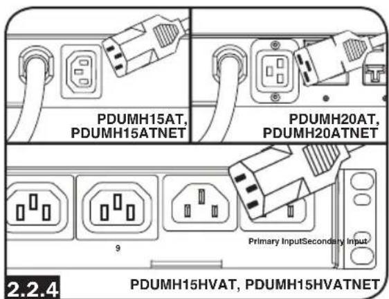
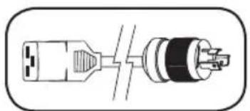
2.2 Connecting the PDU
All PDU models include a primary and secondary AC power input (see diagram). The reference table below lists each model's primary and secondary inputs:
| Model Primary Input Secondary Input* | |
| PDUMH15AT NEMA 5-15P (permanent cord) IEC C14 inlet | |
| PDUMH15ATNET NEMA 5-15P (permanent cord) IEC C14 inlet | |
| PDUMH15HVAT IEC C14 inlet (detachable cord) IEC C14 inlet | |
| PDUMH15HVATNET IEC C14 inlet (detachable cord) IEC C14 inlet | |
| PDUMH20AT NEMA 5-15P (permanent cord) IEC C20 inlet | |
| PDUMH20ATNET NEMA 5-15P (permanent cord) IEC C20 inlet | |
| PDUMH20HVAT IEC C20 inlet (detachable cord) IEC C20 inlet | |
| PDUMH20HVATNET IEC C20 inlet (detachable cord) IEC C20 inlet |
Note: The PDUMH15HVATNET model uses plug lock inserts over C13 plugs to securely connect to the C14 primary and secondary inputs.
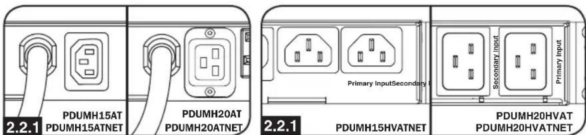
Primary Input (120V Models) Primary Input (208-240V Models)
2. Installation
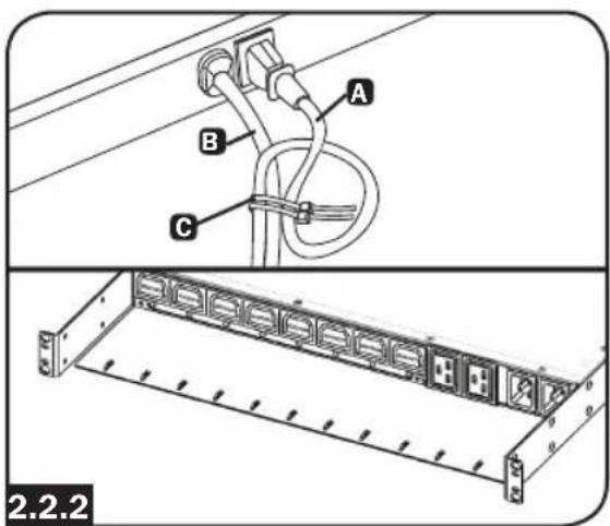
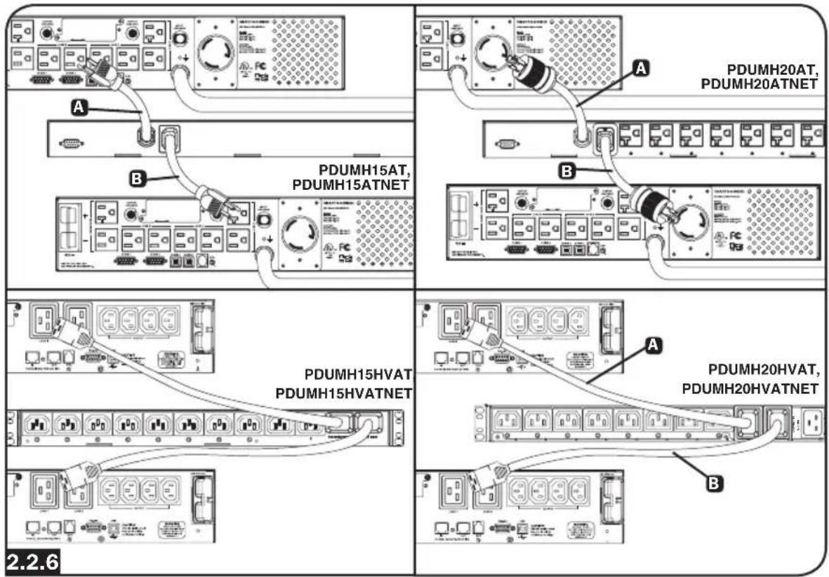
2.2.2 To connect the Secondary input cord:
Form a loop in the Secondary cord A and secure the juncture of that loop to the Primary cord B with a zip tie. Be sure the zip tie is secured around the Secondary and Primary cords, as well as through the loop created in the Secondary cord C. (See diagram).
Note: Allow the cord as much slack as possible between the loop and the cord's outlet.
On Models PDUMH20HVAT and PDUMH20HVATNET, both cords should be tied to the Cable Retention Tray. (See diagram).
Once two cords are secured and the Secondary cord has an acceptable amount of slack, insert the Secondary cord outlet into the IEC power inlet.
Note: The PDUMH15HVATNET model uses plug lock inserts over C13 plugs to securely connect to the C14 primary and secondary inputs.
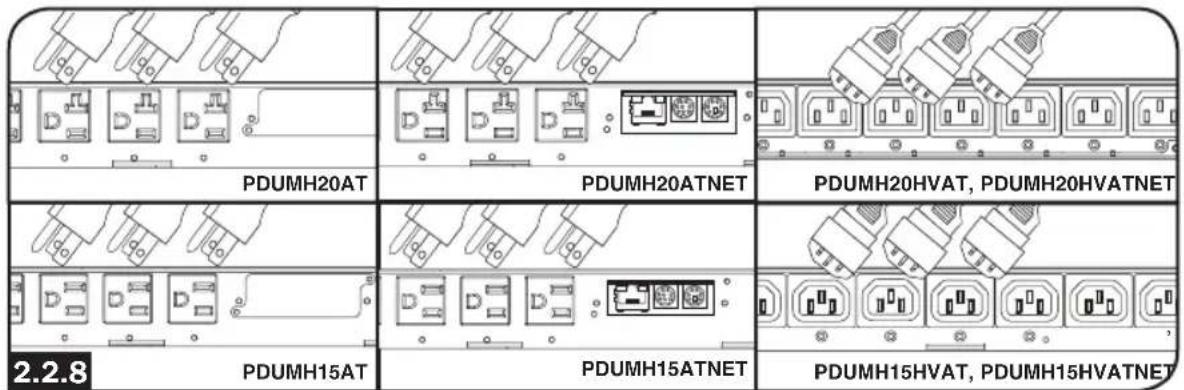
2.2.3 Connect Input Plug Adapters (Optional - Models PDUMH20AT, PDUMH20ATNET Only):
The PDU includes two adapters that convert one or both of the L5-20P input plugs to 5-20P input plugs. Connecting the adapters is optional. The PDU will function normally without connecting the adapters.
2.2.4 Connect Secondary Input Cord to PDU:
Although the PDU will operate without connecting the Secondary input cord, the Secondary input is required for the PDU's Automatic Transfer Switch function.

2. Installation
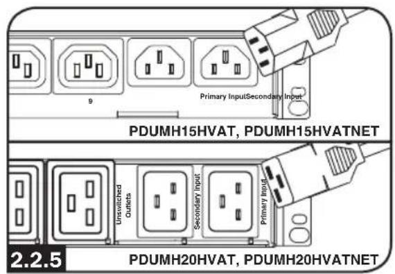
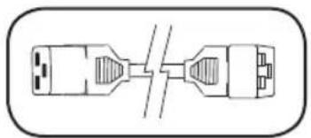
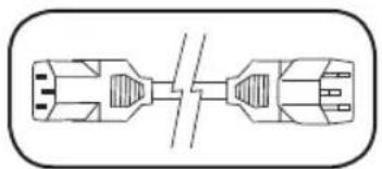
2.2.5 C13-C14 (Models: PDUMH15HVAT and PDUMH15HVATNET) or C19-C20 Cables (Models PDUMH20HVAT and PDUMH20HVATNET only):
The PDU includes one C13 to C14 (PDUMH15HVAT/NET) or two C19 to C20 (PDUMH20HVAT/NET) interconnection cables for the two primary and secondary inlets, which may be used to connect to upstream UPS sources. Alternately, the user can supply IEC cables fitted with country-specific plugs.
2.2.6 Connect PDU Input Plugs:
(See the Configuration and Operation section for more information.) Connect the Primary input plug A to a preferred source of grounded 120V/230V AC power, such as a SmartOnline UPS System. The UPS system must not share a circuit with a heavy electrical load (such as an air conditioner or refrigerator). Under normal operating conditions, the PDU will distribute AC power from the Primary input source. Connect the Secondary input plug B to an alternative source of grounded 120V/230V AC power, such as a redundant SmartOnline UPS System. Do not plug the Secondary input into the same power source as the Primary input. The PDU will distribute AC power from the Secondary input only if the Primary input becomes unavailable.
Note: Immediately after the PDU is connected to live AC power, you may notice a series of soft clicking sounds emitted by electrical relays within the PDU. The relays may also click occasionally during the operation of the PDU. This is normal.
2. Installation
2.2.7 Selecting Input Voltage Range (optional: Models PDUMH15HVAT, PDUMH15HVATNET, PDUMH20HVAT and PDUMNH20HVATNET only):
These models have two selectable nominal input voltage ranges: 200V-208V ("LO") and 220V-240V ("HI"). Press the button next to the display to toggle the nominal voltage setting to the desired "HI" or "LO" range. This setting adjusts the voltage ranges for the primary and secondary inputs. The display will indicate "HI" or "LO" for five seconds.
2.2.8 Connect Equipment to PDU:
Do not exceed the load rating of the PDU. The total electrical current used by the PDU will be displayed on the digital meter in amperes. Each outlet includes a green LED that illuminates when the outlet is receiving AC power.
2.3 Networking the PDU
2.3.1 Preparation
MAC Address: The 12-digit MAC address (000667xxxxx) label is located below the RJ45 jack on the unit's front panel.
Determine Installation Method: If your network's DHCP server will assign a dynamic IP address to the device automatically, proceed to Dynamic IP Address Assignment. If you will assign a static IP address to the device manually, proceed to Static IP Address Assignment. If you are uncertain which method to use, contact your network administrator for assistance before continuing the installation process.
2.3.2 Dynamic IP Address Assignment
Connect to Your Network: Connect a standard Ethernet patch cable to the RJ45 Ethernet port on the unit A.
Note: This port does not support PoE (Power over Ethernet) applications.
On PDUMH20HVATNET, connection is on the reverse side.
The device will attempt to obtain an IP address via DHCP. This may take as long as several minutes, depending on your network environment.
Discover IP Address: Contact your network administrator to determine which IP address has been assigned to the device by the DHCP server. The device can be identified on the DHCP server by referring to its MAC address (see Step 1-3). You may wish to request a long-term lease period for the IP address, depending on your application. After you have discovered the IP address, proceed to 2.4 Test and Configure.
Note: The DHCP address is also displayed during boot-up when connected to a computer through the configuration cable and a terminal emulation program.
2. Installation
IP Address Display (Models PDUMH15HVATNET and PDUMH20HVATNET): Press and hold the button to display the PDU's IP address.
2.3.3 Static IP Address Assignment/Terminal Menu Configuration Settings
Determine IP Information: Before assigning a static IP address, you'll need to know the IP address, gateway address and subnet mask. If you do not have this information, contact your network administrator for assistance.
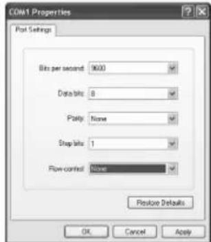
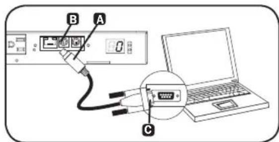
Configure Terminal Emulation Program: Open a VT100-compatible terminal emulation program (such as Tera Term) on a computer with an available DB9 serial port or USB to serial adapter. (A notebook computer may be the most convenient choice.) Set the terminal emulation program to use the COM port
A that corresponds to the computer's serial port. Specify the parameters B required to communicate with the unit's terminal interface:
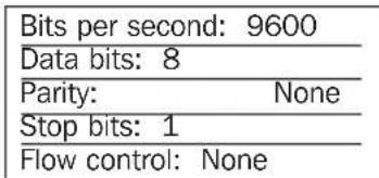
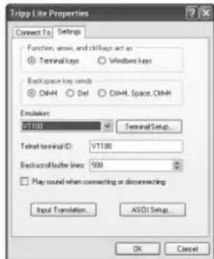
If the terminal emulation program supports multiple emulation modes, you may also need to specify VT100 emulation


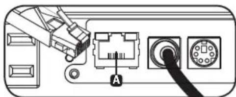
Connect to a Computer: Use the mini-DIN to DB9 serial cable (part number 73-1025) included to connect the device to the computer. The circular connector A at one end of the cable attaches to the 8-pin mini-DIN config port B. (Align the connector carefully to avoid damaging the pins.) The DB9 connector C at the other end of the cable connects to the computer (or USB to serial adapter).
2. Installation
Configure the Network Interface in Terminal Mode: After a brief pause, an initialization page should appear in the terminal emulation program. Press any key on the keyboard within 5 seconds to change the settings. If the 5-second period has elapsed, reboot the network interface. To reboot, use a small paperclip or pointed tool to press the reset button located above the RJ45 network port. (refer to callout 7F in section 3. Features for the reset button location).
The following boot sequence will display in the terminal window:
BSP Version 12.06.xxxx.xxxxx built on [date] [time] by SYSTEM Copyright Tripp Lite 2008-2016, All rights reserved.
...
booting flat image
PLATFORM: tripliteSnmpCard9210_H_16_32 16M/32M
NETWORK INTERFACE PARAMETERS:
FQDN poweralert-0610337151181
The board will obtain IPv4 configuration parameters from the network.
DHCPv6 is enabled on LAN
DNS server is 8.8.8.8
Time is supplied by SNMP at an interval of 360 minutes
Primary SNMP Server host is 0.pool.ntp.org
Secondary SNMP Server host is 1.pool.ntp.org
Time zone is set to -6:00 from GMT, DST Enabled
SERVICES:
FTP is enabled on port 21
HTTP is enabled on port 80
HTTPS is enabled on port 443
SSH is enabled on port 22
SSH is enabled on port 2112
TELNET is enabled on port 23
TELNET is enabled on port 5214
SNMP is enabled on port 161
SYSLOG is disabled
HARDWARE PARAMETERS:
Serial channels will use a baud rate of 9600
RTC date and time in GMT: 07/25/2016 19:00:23
This board's serial number is 2422AY016757C00899
This board's Ethernet MAC Address is 00:06:67:25:97:B5
This board's SNMP engine boot count is 7 (0)
After board is reset, start-up code will wait 5 seconds
Press any key in 5 seconds to change these settings. Egeeranychanaatetewithin 5 seconds to interrupt the bioott sequence
Press A to Accept the settings, or M to Modify? m
Enter the root password:***** The default root password is $T#pplite
Reset configuration and root password to default values?
For each of the following questions, you can press
ETHERNET INTERFACE SETTINGS:
Obtain IPv4 settings automatically using DHCP for Ethernet interface [Y]? NIP address [192.168.1.176]? Entner the data traffic statistic IP路由 Subnet mask [255.255.255.0]? Entner the Subtree maskk Gateway address [192.168.1.1]? Entner the Gateway address
2. Installation
Enable DHCPv6 for the Ethernet interface [Y]?
Enable static IPv6 for the Ethernet interface [N]?
DNS server [8.8.8.8]?
This card's host name [poweralert-0610337151181]?
This card's domain []?
From this point forward, press «Return» for each option to accept the default configuration:
EnableSNTP[Y]?
EnableFTP[Y]?
Port number [21]?
Enable HTTP[Y]?
Port number [80]?
Enable HTTPS[Y]?
Port number [443]?
Enable Telnet Menu[Y]?
Port number [23]?
Enable Telnet Programs[Y]?
Port number [5214]?
Enable SSH Menu[Y]?
Enable SCP[N]?
Port number [22]?
Enable SSH Programs[Y]?
Port number [2112]?
Enable SNMP[Y]?
Port number [161]?
Enable SNMPv1[Y]?
Enable SNMPv2c[Y]?
Enable SNMPv3[Y]?
Do you wish to modify the network watchdog configuration? [N]?
HARDWARE PARAMETERS:
Would you like to update the RTC date/time in GMT [N]?
Time Zone in 30 minute intervals, +/-HH:MM[-06:00] (+ is optional):
Do you wish to configure the advanced settings [y/n]
SECURITY SETTINGS:
Would you like to update the Root Password [N]?
Do you wish to modify the users [N]?
Do you wish to modify the auth and accounting method? [N]?
Do you wish to modify the radius hosts table? [N]?
Erase the server private key passphrase?
Erase the client private key passphrase?
New passphrase for server private key?
Re-enter passphrase for server private key?
New passphrase for client private key?
Re-enter passphrase for client private key?
MISCELLANEOUS SETTINGS:
How long (in seconds) should CPU delay before starting up [5]?
Saving the changes in NV memory...Done.
When "Done" appears, the card will reboot and the assigned static IP will become active. Once the new static IP settings are displayed, proceed to 2.4 Test and Configure.
2. Installation
2.4 Test and Configure
Test Network Connection: After an IP address has been assigned, try to access it with a Web browser that supports frames, forms and Java™. Open a Web browser on a computer connected to the LAN and enter the device's IP address. You should be prompted for a password. The user name is localadmin and the default password is localadmin. After you enter the user name and password, the PowerAlert Status page will appear in the browser window. For more information about configuration and operation of the managed device, refer to the SNMPWEBCARD User's Guide (available for download at www.triplite.com).
Note for Network Management System Users Only: Tripp Lite MIB files must be loaded on each Network Management Station that will monitor the UPS system via SNMP. The files are available at www.triplite.com.
3. Features
Models PDUMH15AT/PDUMH15AT/NET: The cord is permanently attached to the PDU and has a NEMA 5-15P plug.
Models PDUMH15HVAT/NET: The C13-C14 cord is detachable.
Models PDUMH20AT/NET: The cord is permanently attached to the PDU and has a NEMA L5-20P plug.
Models PDUMH20HVAT/NET: The C19-C20 cord is detachable.
2 Secondary Input Inlet (detachable on all models)
Models PDUMH15AT/15ATNET/15HVATNET: The IEC-320-C14 inlet connects to the detachable Secondary AC Input Power Cord.
Models PDUMH20AT/20ATNET/20HVAT/20HVATNET: The IEC-320-C20 inlet connects to the detachable Secondary AC Input Power Cord.
Switched Outlets: During normal operation, the outlets distribute AC power to connected equipment. On Models PDUMH15ATNET, PDUMH15HVATNET, PDUMH20ATNET and PDUMH20HVATNET, the NEMA 5-15R, NEMA 5-15/20R and IEC-320-C13 outlets may be switched On and Off via software control. When an outlet is live, the associated LED illuminates.
4 Unswitched Outlets (PDUMH20HVAT & PDUMH20HVATNET only): These outlets receive power from either input source, but are not individually switchable.
5 Factory Config Port: The port is reserved for configuration by factory authorized personnel only. No user information is available. Connecting to this port may render the unit inoperable and void its warranty.
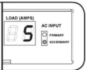
6 Digital Load Meter (Ammeter): The total electrical current used by the connected equipment is displayed on the digital meter in amperes.
Input Voltage Range Select Switch (Models PDUMH15HVATNET, PDUMH20HVATNET): The button to the lower left of the display may be used to toggle between "HI" or "LO" voltage ranges. The display will indicate "HI" or "LO" for five seconds. Press the switch once to display ranges, press again within five seconds to change setting. Setting can also be changed via PowerAlert (PDUMH15HVATNET and PDUMH20HVATNET only).
IP Address Display (Models PDUMH15HVATNET, PDUMH20HVAT, PDUMH20HVATNET):
Press and hold the switch to display the IP address of the SNMP card in the PDU.
Network Interface (PDUMH15ATNET, PDUMH15HVATNET, PDUMH20ATNET, PDUMH20HVATNET only)
A RJ45 Jack: Connects the ATS to the network with a standard Ethernet patch cable.
B C LEDs: Indicate Several Operating Conditions
| 3 Link LED Color | C Status LED Color | |
| Off No Network Connection Off Card Not Initialized | ||
| Flashing Amber 100 Mbps Network Connection Steady | Green Card Initialized and Operational | |
| Flashing Green 10 Mbps Network Connection Flashing | Amber Error - Card Not Initialized | |
D DIN Configuration Port: Provides a direct terminal connection to a computer with a terminal emulation program. A serial cable (part number 73-1025) is included with the PDU. To order a replacement cable, contact Tripp Lite Customer Support at 773.869.1234.
3. Features
ENVIROSENSE Port: Use this port to connect a Tripp Lite ENVIROSENSE environmental sensor to provide remote temperature/humidity monitoring and a dry contact interface to control and monitor alarm, security and telecom devices. Visit www.triplite.com for more information on this product.
Note: Do not connect a keyboard or mouse to this port.
Models PDUMH15AT, PDUMH15HVAT, PDUMH20AT and PDUMH20HVAT contain a built-in slot that supports the optional SNMPWEBCARD accessory (sold separately).
Reset Button: To reset the network interface, use a small paperclip or pointed tool to press the reset button located above the RJ45 network port.
Input Source Indicator: When the PDU is connected to a live AC power source, the Primary or Secondary input LED illuminates to indicate which source is supplying power to the outlets.
Primary and Secondary AC Input Power Cord (Models PDUMH20HVAT, PDUMH20HVATNET): Two C19-C20 cables are included: one for Primary Input, and one for Secondary Input.
Primary AC Input Power Cord (Models PDUMH15HVAT, PDUMH15HVATNET): A C13-C14 cable is included.
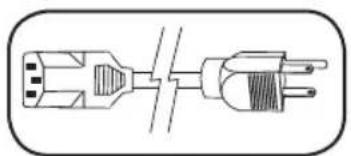
Secondary AC Input Power Cord (Models PDUMH15AT, PDUMH15ATNET): The detachable cord has an IEC-320-C13 connector and a NEMA 5-15P plug.
Secondary AC Input Power Cord (Models PDUMH20AT, PDUMH20ATNET): The detachable cord has an IEC-320-C19 connector and a NEMA L5-20P plug.

Input Plug Adapters (Models PDUMH20AT, PDUMH20ATNET): The adapters convert NEMA L5-20P input plugs to NEMA 5-20P input plugs.
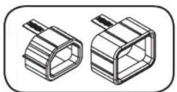
Plug Lock Inserts (Models PDUMH15HVAT, PDUMH15HVATNET): Prevent accidental disconnection of C13-C14 or C19-C20 power cords.

Cable Retention Tray (Models PDUMH20HVAT, PDUMH20HVATNET): Tie the Primary and Secondary Input cords to the Cable Retention Tray. Once you've secured the two cords together and ensured that the Secondary cord has a comfortable amount of slack, insert the Secondary cord outlet into the IEC power inlet.
4. Configuration and Operation
4.1 Automatic Transfer Switch
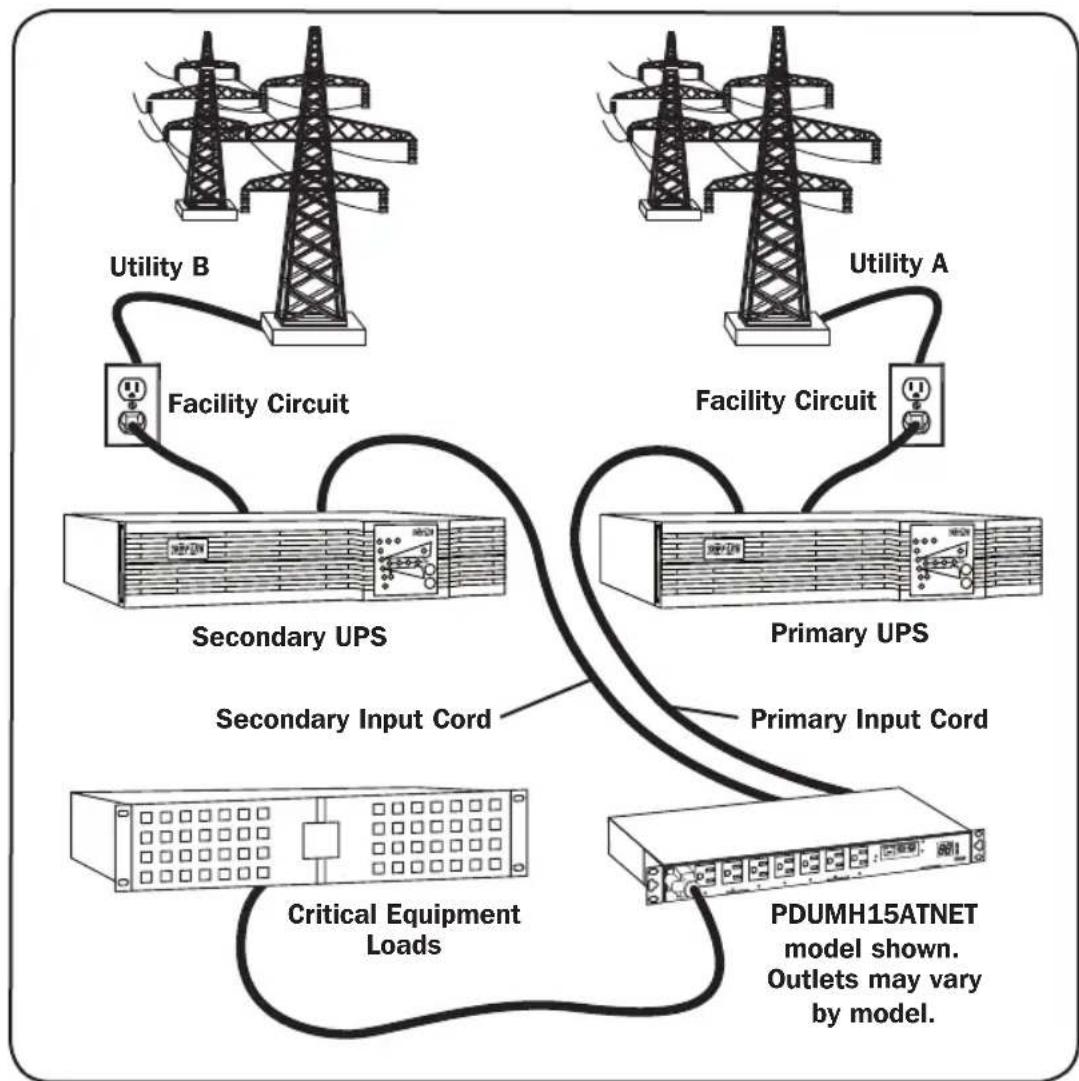
When the Primary and Secondary inputs are both connected to Tripp Lite UPS Systems, the PDU operates as an Automatic Transfer Switch, providing redundant input power for high availability applications. Under normal operating conditions, the PDU will distribute power from the Primary input source, switching to the Secondary input source under certain conditions. The PDU will switch to the Primary source whenever it is "Good" according to the PDU input voltage definitions (see section 4.1.2 for more information).
4.1.1 Preferred Configuration
The Automatic Transfer Switch function provides increased availability when the Primary and Secondary inputs of the PDU are connected to separate Tripp Lite UPS Systems that are connected to separate utility power sources. For maximum availability, Tripp Lite recommends using matching SmartOnline UPS Systems with pure sine wave output for the Primary and Secondary input power sources. The automatic transfer switch function will be compromised if the primary and secondary inputs are connected to the same utility power source.
Warning: DO NOT connect the primary input to a line-interactive UPS, due to transfer time issues, or to any source that does not supply a pure sine wave. Such sources may be used to power the secondary input.
4. Configuration and Operation
4.1.2 Automatic Transfer Switch Source Selection
The PDU will power up if one of the input sources is greater than the minimum startup voltage. In normal operation (after power-up), if the presently selected source (primary or secondary) degrades to a lesser condition, the unit should switch to the alternate source, if that source is of better quality. The unit prefers the primary source, and will always switch to it in the event that both sources are of the same (fair or good) quality. If the present source is becoming bad and the alternate source is at least fair, the unit will switch to the alternate source.
| Nominal Voltage of PDU | |||
| Low-Voltage Models High-Voltage Models | |||
| 120V 200-208V | 220-240V | ||
| Minimum Startup Voltage | 85V 163V 163V | ||
| Good Voltage Range | 99-139V 172-241V | 190-266V | |
| Fair Voltage Range | 75-98V 144-171V | 144-189V | |
| Bad Voltage Range | 0-74V 0-143V 0-1 | 43V | |
4.1.3 Quick Test
After installing the PDU and connecting equipment, you may test the Automatic Transfer Switch function by temporarily shutting down the UPS system connected to the Primary AC input. When the Primary input UPS is no longer supplying AC power, the PDU will switch from the Primary input to the Secondary input, and the Secondary input LED will illuminate. When the Primary input UPS has
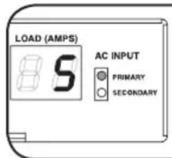
Primary Input Active
Secondary Input Active
been restarted and resumes supplying AC power, the PDU will switch back to the Primary input.
Note: The primary and secondary inputs must be connected to separate sources of utility power. The automatic transfer switch function will be compromised if the primary and secondary inputs are connected to the same utility power source. Do not perform a test with equipment that must remain in productive operation. Any test procedure must prepare for the contingency that the equipment may lose power. Do not test the PDU by detaching power cords which are connected to live power sources, as this eliminates the connection to ground and places your equipment at risk.
4.2 Remote Monitoring and Control
The PDU provides remote monitoring, outlet control and more via Web browser, telnet and SNMP-based Network Management Systems. For more information about configuration and operation of the PDU via the PowerAlert Web browser interface, refer to the SNMPWEBCARD User's Guide (available for download at www.triplite.com).
Load "Ramping" on Startup: All models arrive from the factory programmed so that, when first powered up, their outlets turn on in sequential order at intervals of approximately 250 ms. This prevents circuit overloads by staggering the startup of multiple devices. Models PDUMH15ATNET, PDUMH15HVATNET, PDUMH20ATNET and PDUMH20HVATNET support user-programmable startup of outlets, in any order or time interval. This ensures that network items are turned on in the proper sequence, with the appropriate delay, so that network items are reliably discovered on startup.
Programmable Load "Shedding" During a Power Failure: In the event that the primary power source fails and the PDU is relying on the secondary power source, load shedding allows you to program the shutoff of specific outlets at timed intervals. This enables you to turn off less critical loads (monitors, for example) to maximize the UPS runtime for the most critical items.
5. Technical Support
www.triplite.com/support
E-mail: techsupport@tripplite.com
6. Warranty and Product Registration
LIMITED WARRANTY
Seller warrants this product, if used in accordance with all applicable instructions, to be free from original defects in material and workmanship for a period of 2 years (except internal UPS system batteries outside USA and Canada, 1 year) from the date of initial purchase. If the product should prove defective in material or workmanship within that period, Seller will repair or replace the product, in its sole discretion. Service under this Warranty can only be obtained by your delivering or shipping the product (with all shipping or delivery charges prepaid) to: Tripp Lite, 1111 W. 35th Street, Chicago, IL 60609 USA. Seller will pay return shipping charges. Visit www.triplite.com/support before sending any equipment back for repair.
THIS WARRANTY DOES NOT APPLY TO NORMAL WEAR OR TO DAMAGE RESULTING FROM ACCIDENT, MISUSE, ABUSE OR NEGLECT. SELLER MAKES NO EXPRESS WARRANTY OTHER THAN THE WARRANTY EXPRESSLY SET FORTH HEREIN. EXCEPT TO THE EXTENT PROHIBITED BY APPLICABLE LAW, ALL IMPLIED WARRANTYES, INCLUDING ALL WARRANTYES OF MERCHANTABILITY OR FITNESS, ARE LIMITED IN DURATION TO THE WARRANTY PERIOD SET FORTH ABOVE; AND THIS WARRANTY EXPRESSLY EXCUSES ALL INCIDENTAL AND CONSEQUENTIAL DAMAGES. (Some states do not allow limitations on how long an implied warranty lasts, and some states do not allow the exclusion or limitation of incidental or consequential damages, so the above limitations or exclusions may not apply to you. This Warranty gives you specific legal rights, and you may have other rights which vary from jurisdiction to jurisdiction).
WARNING: The individual user should take care to determine prior to use whether this device is suitable, adequate or safe for the use intended. Since individual applications are subject to great variation, the manufacturer makes no representation or warranty as to the suitability or fitness of these devices for any specific application.
PRODUCT REGISTRATION
Visit www.triplite.com/warranty today to register your new Tripp Lite product. You'll be automatically entered into a drawing for a chance to win a FREE Tripp Lite product!*
- No purchase necessary. Void where prohibited. Some restrictions apply. See website for details.
FCC Notice
This device complies with part 15 of the FCC Rules. Operation is subject to the following two conditions: (1) This device may not cause harmful interference, and (2) this device must accept any interference received, including interference that may cause undesired operation.
This equipment has been tested and found to comply with the limits for a Class A digital device, pursuant to part 15 of the FCC Rules. These limits are designed to provide reasonable protection against harmful interference when the equipment is operated in a commercial environment. This equipment generates, uses, and can radiate radio frequency energy and, if not installed and used in accordance with the instruction manual, may cause harmful interference to radio communications. Operation of this equipment in a residential area is likely to cause harmful interference in which case the user will be required to correct the interference at his own expense. The user must use shielded cables and connectors with this product. Any changes or modifications to this product not expressly approved by the party responsible for compliance could void the user's authority to operate the equipment.
Regulatory Compliance Identification Numbers
For the purpose of regulatory compliance certifications and identification, your Tripp Lite product has been assigned a unique series number. The series number can be found on the product nameplate label, along with all required approval markings and information. When requesting compliance information for this product, always refer to the series number. The series number should not be confused with the marking name or model number of the product.
Tripp Lite has a policy of continuous improvement. Specifications are subject to change without notice.


1111 W. 35th Street, Chicago, IL 60609 USA • www.triplite.com/support
BSP Version 12.06.xxxx.xxxxx built on [date] [time] by SYSTEM Copyright Tripp Lite 2008-2016, All rights reserved.
...
booting flat image
PLATFORM: tripliteSnmpCard9210_H_16_32 16M/32M
NETWORK INTERFACE PARAMETERS:
FQDN poweralert-0610337151181
The board will obtain IPv4 configuration parameters from the network.
DHCPv6 is enabled on LAN
DNS server is 8.8.8.8
Time is supplied by SNMP at an interval of 360 minutes
Primary SNMP Server host is O.pool.ntp.org
Secondary SNMP Server host is 1.pool.ntp.org
Time zone is set to -6:00 from GMT, DST Enabled
SERVICES: FTP is enabled on port 21 HTTP is enabled on port 80 HTTPS is enabled on port 443 SSH is enabled on port 22 SSH is enabled on port 2112 TELNET is enabled on port 23 TELNET is enabled on port 5214 SNMP is enabled on port 161 SYSLOG is disabled
HARDWARE PARAMETERS:
Serial channels will use a baud rate of 9600
RTC date and time in GMT: 07/25/2016 19:00:23
This board's serial number is 2422AY016757c00899
This board's Ethernet MAC Address is 00:06:67:25:97:B5
This board's SNMP engine boot count is 7 (0)
After board is reset, start-up code will wait 5 seconds
Press any key in 5 seconds to change these settings. Enter any characters within 5 seconds to interrupt the boot sequences
Press A to Accept the settings, or M to Modify? mm
Enter the root password: ******* The default root password is T#ppliee
Reset configuration and root password to default values?
For each of the following questions, you can press
ETHERNET INTERFACE SETTINGS:
Obtain IPv4 settings automatically using DHCP for Ethernet interface [Y]? NN
IP address [192.168.1.176]? Entner thee dassireed statistic IP? hee
Subnet mask [255.255.255.0]? Entner thee Subnreatt maskk
Gateway address [192.168.1.1]? Entner thee Gateway address
2. Instalación
Enable DHCPv6 for the Ethernet interface [1]
Enable static IPv6 for the Ethernet interface [N]?
DNS server [8.8.8.8]?
This card's host name [poweralert-0610337151181]?
This card's domain []?
From this point forward, press «Return» for each option to accept the default configuration:
EnableSNTP[Y]?
Enable FTP [Y]?
Port number [21]?
Enable HTTP [Y]?
Port number [80]?
Enable HTTPS [Y]?
Port number [443]?
Enable Telnet Menu [Y]?
Port number [23]?
Enable Telnet Programs [Y]?
Port number [5214]?
Enable SSH Menu [Y]?
Enable SCP [N]?
Port number [22]?
Enable SSH Programs [Y]?
Port number [2112]?
EnableSNMP[Y]?
Port number [161]?
EnableSNMPv1[Y]?
EnableSNMPv2c[Y]?
EnableSNMPv3[Y]?
Do you wish to modify the network watchdog configuration? [N]?
HARDWARE PARAMETERS:
Would you like to update the RTC date/time in GMT [N]?
Time Zone in 30 minute intervals, + / - HH:MM[-06:00] (+ is optional):
Do you wish to configure the advanced settings [y/n]
SECURITY SETTINGS:
Would you like to update the Root Password [N]?
Do you wish to modify the users [N]?
Do you wish to modify the auth and accounting method? [N]?
Do you wish to modify the radius hosts table? [N]?
Erase the server private key passphrase?
Erase the client private key passphrase?
New passphrase for server private key?
Re-enter passphrase for server private key?
New passphrase for client private key?
Re-enter passphrase for client private key?
MISCELLANEOUS SETTINGS:
How long (in seconds) should CPU delay before starting up [5]?
Saving the changes in NV memory...Done.
www.triplite.com/support
Correo Electrónica: techsupport@tripplite.com
6. Garantía
GARANTÍA LIMITADA
1111 W. 35th Street, Chicago, IL 60609 USA • www.triplite.com/support
BSP Version 12.06.xxxx.xxxxx built on [date] [time] by SYSTEM Copyright Tripp Lite 2008-2016, All rights reserved.
...
booting flat image
PLATFORM: tripliteSnmpCard9210_H_16_32 16M/32M
NETWORK INTERFACE PARAMETERS:
FQDN poweralert-0610337151181
The board will obtain IPv4 configuration parameters from the network.
DHCPv6 is enabled on LAN
DNS server is 8.8.8.8
Time is supplied by SNMP at an interval of 360 minutes
Primary SNMP Server host is 0.pool.ntp.org
Secondary SNMP Server host is 1.pool.ntp.org
Time zone is set to -6:00 from GMT, DST Enabled
SERVICES:
FTP is enabled on port 21
HTTP is enabled on port 80
HTTPS is enabled on port 443
SSH is enabled on port 22
SSH is enabled on port 2112
TELNET is enabled on port 23
TELNET is enabled on port 5214
SNMP is enabled on port 161
SYSLOG is disabled
HARDWARE PARAMETERS:
Serial channels will use a baud rate of 9600
RTC date and time in GMT: 07/25/2016 19:00:23
This board's serial number is 2422AY016757C00899
This board's Ethernet MAC Address is 00:06:67:25:97:B5
This board's SNMP engine boot count is 7 (0)
After board is reset, start-up code will wait 5 seconds
Press any key in 5 seconds to change these settings. Enter a y chater width n 5 seconds to interrupt tthe bocott sequence
Press A to Accept the settings, or M to Modify? mm
Enter the root password: \*\*\*\*\*\*\*\* The default root password is TjppbIe
Reset configuration and root password to default values?
For each of the following questions, you can press
ETHERNET INTERFACE SETTINGS:
Obtain IPv4 settings automatically using DHCP for Ethernet interface [Y]? NN
IP address [192.168.1.176]? Enter the dssifed statistic IP hicee
Subnet mask [255.255.255.0]? Enter the SubnreRt maskk
2. Installation
Gateway address [192.168.1.1]? Entner the Gateway address
Enable DHCPv6 for the Ethernet interface [Y]?
Enable static IPv6 for the Ethernet interface [N]?
DNS server [8.8.8.8]?
This card's host name [poweralert-0610337151181]?
This card's domain []?
From this point forward, press
EnableSNTP[Y]?
Enable FTP [Y]?
Port number [21]?
Enable HTTP [Y]?
Port number [80]?
Enable HTTPS [Y]?
Port number [443]?
Enable Telnet Menu [Y]?
Port number [23]?
Enable Telnet Programs [Y]?
Port number [5214]?
Enable SSH Menu [Y]?
Enable SCP [N]?
Port number [22]?
Enable SSH Programs [Y]?
Port number [2112]?
EnableSNMP[Y]?
Port number [161]?
EnableSNMPv1[Y]?
EnableSNMPv2c[Y]?
EnableSNMPv3[Y]?
Do you wish to modify the network watchdog configuration? [N]?
HARDWARE PARAMETERS:
Would you like to update the RTC date/time in GMT [N]?
Time Zone in 30 minute intervals, +/-HH:MM[-06:00] (+ is optional):
Do you wish to configure the advanced settings [y/n]
SECURITY SETTINGS:
Would you like to update the Root Password [N]?
Do you wish to modify the users [N]?
Do you wish to modify the auth and accounting method? [N]?
Do you wish to modify the radius hosts table? [N]?
Erase the server private key passphrase?
Erase the client private key passphra
New passphrase for server private key?
Re-enter passphrase for server private key?
New passphrase for client private key?
Re-enter passphrase for client private key?
MISCELLANEOUS SETTINGS:
How Long (in seconds) should CPU delay before starting up [5]?
Saving the changes in NV memory...Done.
www.triplite.com/support

Manufacturing Excellence
1111 W. 35th Street, Chicago, IL 60609 USA • www.triplite.com/support