B127A1A1BHPH - Receiver Tripp Lite - Free user manual and instructions
Find the device manual for free B127A1A1BHPH Tripp Lite in PDF.
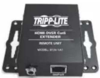
| Product Type | HDMI over Cat6 Receiver with Integrated HDMI Male Cable (Pigtail) |
| Maximum Video Resolution | 4K x 2K (3840 x 2160) at 60 Hz with 4:4:4 Subsampling |
| Maximum Transmission Distance | 70 m (230 ft) with 24 AWG Solid Wire Cat6 Cable |
| HDCP Compatibility | HDCP 2.2 |
| HDR Support | Yes |
| Supported Audio Channels | Up to 7.1 Channels |
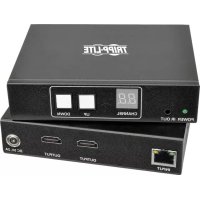
| Input Connector (from Transmitter) | RJ45 (Cat6) |
| Output Connector (to Display) | Integrated 0.3 m (1 ft) HDMI Male Cable |
| Power | Power over Cable (PoC) from Transmitter; No External Power Required |
| Integrated Equalizer | Yes, Adjustable for Distance Compensation |
| Automatic EDID Adjustment | Yes |
| USB/IR Functions | Not Integrated on This Receiver Model (Available via Transmitter and Receiver of Other Models in Series) |
| Mounting Included | Hardware for Wall, 19" Rack, or Pole Mounting |
| Dimensions (Approx.) | 8 x 5 x 2 cm |
| Weight (Approx.) | 100 g |
| Warranty | 1 Year (Tripp Lite Limited Warranty) |
Frequently Asked Questions - B127A1A1BHPH Tripp Lite
User questions about B127A1A1BHPH Tripp Lite
0 question about this device. Answer the ones you know or ask your own.
Ask a new question about this device
Download the instructions for your Receiver in PDF format for free! Find your manual B127A1A1BHPH - Tripp Lite and take your electronic device back in hand. On this page are published all the documents necessary for the use of your device. B127A1A1BHPH by Tripp Lite.
USER MANUAL B127A1A1BHPH Tripp Lite
HDMI over Cat6 Extender Kits and Repeater, 4K/60 Hz
Extender Kit Models: B127A-1A1-BHBH, B127A-1A1-BHPH, B127A-111-BHTH, B127A-110-BH Repeater Model: B127A-010-H
Espanol 27 • Français 53 • Pycckn 79 • Deutsch 105
WARRANTY REGISTRATION
Register your product today and be automatically entered to win an ISOBAR® surge protector in our monthly drawing!
triplite.com/warranty
TRIPP·LITE


HHH DPPITTCN 1
1111 W. 35th Street, Chicago, IL 60609 USA • tripplite.com/support
Copyright © 2021 Tripp Lite. All rights reserved.
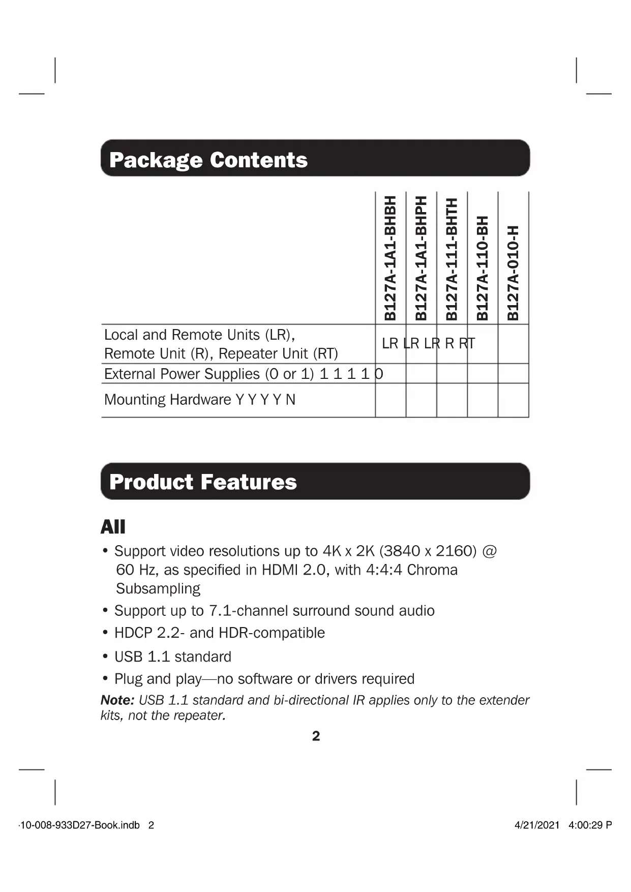
Package Contents
| B127A-1A1-BHBH | B127A-1A1-BHPH | B127A-111-BHTH | B127A-110-BH | B127A-010-H | |
| Local and Remote Units (LR), Remote Unit (R), Repeater Unit (RT) | LR | LR LR | R RT | ||
| External Power Supplies (0 or 1) 1 1 1 1 | 0 | ||||
| Mounting Hardware Y Y Y Y N |
Product Features
All
- Support video resolutions up to 4K x 2K (3840 x 2160) @ 60 Hz, as specified in HDMI 2.0, with 4:4:4 Chroma Subsampling
- Support up to 7.1-channel surround sound audio
- HDCP 2.2- and HDR-compatible
USB 1.1 standard - Plug and play—no software or drivers required
Note: USB 1.1 standard and bi-directional IR applies only to the extender kits, not the repeater.
Product Features
B127A-1A1-BHBH
- HDMI over Cat6 Power over Cable (PoC) Extender Kit
- Extends a 4K x 2K (3840 x 2160) @ 60 Hz signal, as specified in HDMI 2.0, up to 230 ft. (70 m) from the source
Built-in local HDMI port supports 4K @ 60 Hz signal - Remote receiver unit features built-in equalization (EQ) control and auto EDID image adjustment
Supports up to 7.1-channel surround sound audio - Receiver features built-in Toslink port for audio extraction function
- HDCP 2.2-compatible
- Plug and play—no software or drivers required
- Support bi-directional IR and USB 1.1 function by dip switch selection
- Includes mounting hardware that enables both the local transmitter and remote receiver units to be wall-mounted, rack-mounted or pole-mounted
- Power over Cable (PoC) function allows external power supply to be plugged in at either transmitter or receiver side and provide power to both units
Product Features
B127A-1A1-BHPH
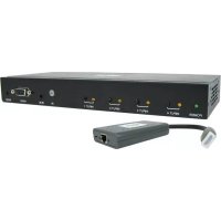
- HDMI over Cat6 Power over Cable (PoC) Extender Kit with Pigtail Receiver
- Extends a 4K x 2K (3840 x 2160) @ 60 Hz signal, as specified in HDMI 2.0, up to 230 ft. (70 m) from the source
Built-in local HDMI port supports 4K @ 60 Hz signal - Remote receiver unit features built-in equalization (EQ) control and auto EDID image adjustment with 1 ft. HDMI male cable
Supports up to 7.1-channel surround sound audio - HDCP 2.2-compatible
- Plug and play—no software or drivers required
- Includes mounting hardware that enables both the local transmitter and remote receiver units to be wall-mounted, rack-mounted or pole-mounted
- Power over Cable (PoC) function allows external power supply to be plugged into transmitter and provide power to both units
Product Features
B127A-111-BHTH
- HDMI over Cat6 Power over Cable (PoC) daisy-chainable Extender Kit
- Remote transceiver unit features built-in equalization (EQ) control, auto EDID image adjustment and RJ45 expanding port to be able to connect to next B127A-110-BH
- Transceiver features built-in Toslink port for audio extraction function
- Extends and expands a 4K x 2K (3840 x 2160) @ 60 Hz signal, as specified in HDMI 2.0, in an over Cat6 installation, allowing multiple monitors to be located at different points in a chain by adding up to four B127A-110-BH units
- Extends a 4K (3840 x 2160) @ 60 Hz signal up to an additional 230 ft. or a 1080p @ 60 Hz signal up to an additional 230 ft. from each remote/repeater unit to the next unit in the chain (in a full four-level daisy chain installation), a 4K (3840 x 216) @ 60 Hz signal up to 920 ft. or a 1080p @ 60 Hz signal up to 500 ft. from the source to the last remote unit in the chain
Supports up to 7.1-channel surround sound audio - Transceiver features built-in Toslink port for audio extraction function
Product Features
- HDCP 2.2-compatible
- Plug and play—no software or drivers required
- Includes mounting hardware that allows unit to be wall-mounted, rack-mounted or pole-mounted
- Power over Cable (PoC) function allows external power supply to be plugged into either transmitter or receiver side and provide power to connected units
B127A-110-BH
- HDMI over Cat6 Power over Cable (PoC) transceiver unit
- Works with the B127A-111-BHTH to extend a 4K x 2K (3840 x 2160) @ 60 Hz signal, as specified in HDMI 2.0, up to 230 ft. (70 m)
- This transceiver unit features built-in equalization (EQ) control and auto EDID image adjustment and one RJ-45 expanding port to be able to connect to next B127A-110-BH
- Transceiver features built-in Toslink port for audio extraction function
Product Features
B127A-010-H
- Repeater unit extends the transmission of a 4K x 2K (3840 x 2160) @ 60 Hz signal, as specified in HDMI 2.0, up to a total of 400 ft. (120 m)
- Power over Cable (PoC) technology means no external power is required to power the unit
- HCDP 2.2- and HDR-compliant
Supports up to 7.1-channel surround sound audio
Optional Accessories:
N202-Series Cat6 24 AWG Solid Wire Patch Cables
- P569-XXX-CERT or P568-XXX-2A Series High-Speed HDMI 2.0 Cables
Disclaimer
Before installation, please check the following settings of your source(s) and TV/monitor(s):
- Set display to 60Hz . Double-check factory settings, as default can be set to a lower frequency (Hz) than advertised.
- Ensure the input setting of your monitor is set at HDMI 2.0. Some displays may have default setting at HDMI 1.4.
- Verify your monitor has the HDR feature enabled. Some displays may have this feature disabled as a factory setting.
- Check if the Ultra HD (UHD) Deep Color setting is enabled on your TV/monitor. Confirm with your TV/monitor manufacturer which HDMI ports support UHD Deep Color.
- Check USB/IR DIP switch, as the default setting is set to IR.
Note: To connect a local monitor to your installation, the UHD Deep Color setting may need to be disabled on your local TV/monitor (depending make/mode) to achieve 4K @ 60 Hz resolution.
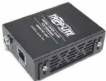
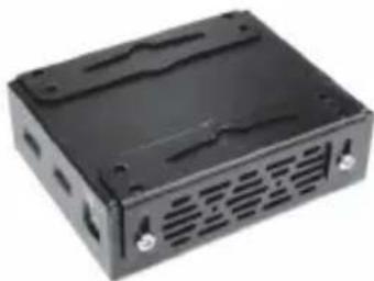
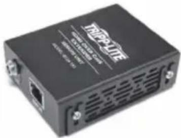
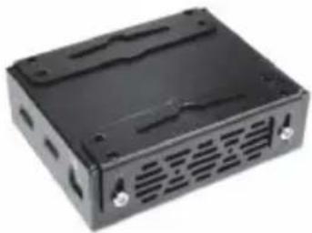
Mounting Instructions (select models only)
The B127A-1A1-BHBH, B127A-1A1-BHPH, B127A-111-BHTH and B127A-110-BH include mounting hardware that allows for a variety of mounting methods.
The following images illustrate how the included mounting brackets can be attached for different installations.
Note: The model shown in the below images is for illustrative purposes only. Your product may vary by model number, size or port orientation. The mounting options for all over IP units are the same.
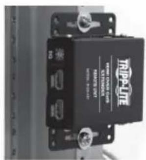
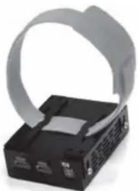
Wall-Mount
19" Rack-Mount Pole-Mount
Standard Extender Kit Installation
Notes:
1) Test to ensure the entire installation works properly before pulling cables through ceilings/walls.
2) To achieve maximum distance and performance, use 24 AWG solid wire Cat6 cable. Using stranded wire Cat6 cable or cable with a gauge (AWG) size higher than 24 AWG will result in shorter extension distance. Higher gauge cabling, such as 26 AWG, has a more limited transmission capability than lower gauge cabling. All Tripp Lite N202-Series Cat6 cables are made with 24 AWG solid wire cabling.
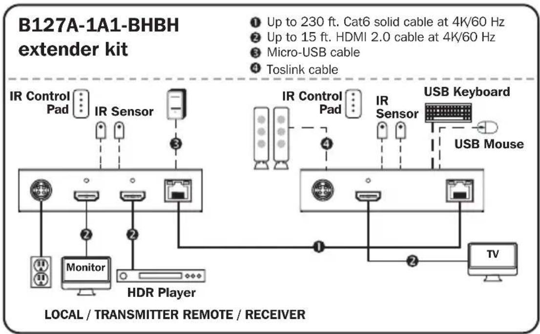
3) The installation diagram shows a B127A-1A1-BHBH unit.
4) External power is not required for remote receiver units due to Power over Cable (PoC) technology incorporated in the transmitter units.
Standard Extender Kit Installation
- Make sure all equipment in the installation—such as TVs, Blu-ray™ players and the transmitter—is powered OFF.
- Using an HDMI 2.0 cable (such as Tripp Lite P569-XXX-CERT or P568-XXX-2A Series cables), connect the HDMI source to the INPUT port on the local transmitter unit.
- Optional for B127A-1A1-BHBH: Using an HDMI 2.0 cable (such as Tripp Lite P569-XXX-CERT or P568-XXX-2A Series cables), connect a local monitor to the LOCALOUT port on the B127A-1A1-BHBH local transmitter unit.
- Optional: For extended range, connect a B127A-010-H signal repeater unit to the transmitter and receiver via Cat6 cabling. See B127A-010-H product features for more information.
- Using Cat6 cable, connect the RJ45 port on the local transmitter unit to the RJ45 port on the remote receiver unit.
- Using an HDMI 2.0 cable (such as Tripp Lite P569-XXX-CERT or P568-XXX-2A Series cables), connect the remote receiver unit's HDMI port to a monitor.
- Turn on the power to your connected TVs/monitors. The LOCAL (orange) LED will illuminate to indicate the local port has been connected to a display.
Standard Extender Kit Installation
- Connect the external power supply to either the transmitter or receiver unit. Plug it into an available wall outlet or a Tripp Lite surge protector, power distribution unit (PDU) or uninterruptible power supply (UPS). The POWER (green) LED on the local transmitter unit will illuminate to indicate the unit is receiving power from the external power supply. The POWER (green) LED on the remote receiver unit will illuminate to indicate the unit is receiving power from the local transmitter unit through PoC technology.
- Turn on the power to the HDMI source. The OUTPUT (orange) LED on the local transmitter unit will illuminate to indicate a signal is being received from the source.
- The (orange) RJ45 LED will illuminate on both the local transmitter and remote receiver units to indicate a signal is being received from the source to display. The screen should now display on the connected monitor(s).
Standard Extender Kit Installation
Notes:
1) Test to ensure the entire installation works properly before pulling cables through ceilings/walls.
2) To achieve maximum distance and performance, use 24 AWG solid wire Cat6 cable. Using stranded wire Cat6 cable or cable with a gauge (AWG) size higher than 24 AWG will result in shorter extension distance. Higher gauge cabling, such as 26 AWG, has a more limited transmission capability than lower gauge cabling. All Tripp Lite N202-Series Cat6 cables are made with 24 AWG solid wire cabling.
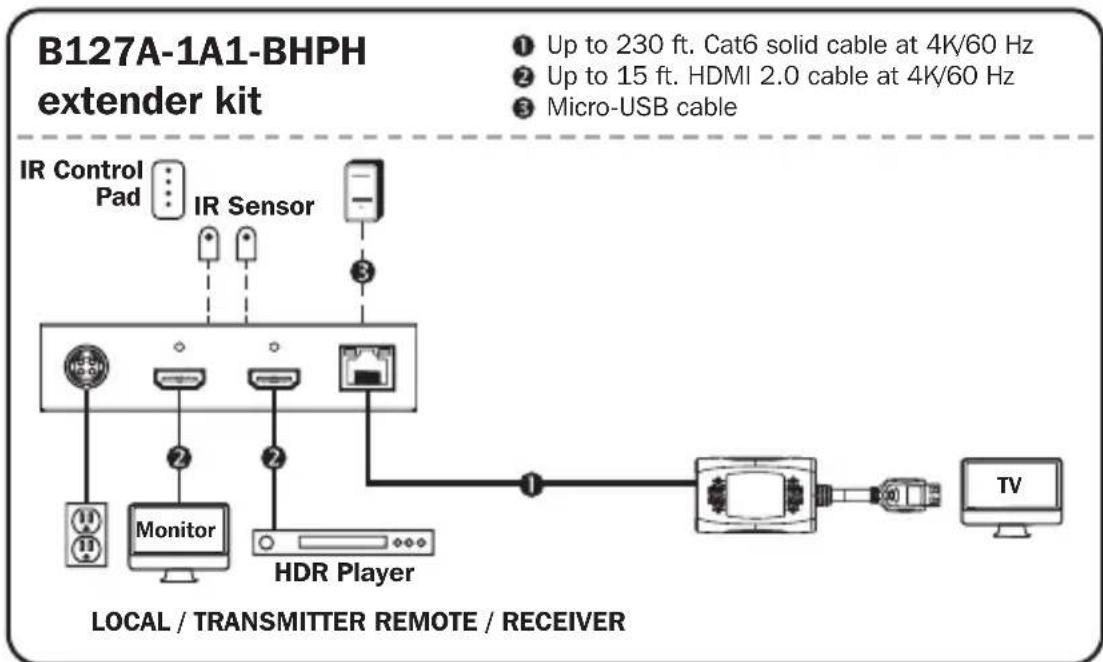
3) The installation diagram shows a B127A-1A1-BHPH unit.
4) External power is not required for remote receiver units due to Power over Cable (PoC) technology incorporated in the transmitter units.
Standard Extender Kit Installation
- Make sure all equipment in the installation—such as TVs, Blu-ray players and the transmitter—is powered OFF.
- Using an HDMI 2.0 cable (such as Tripp Lite P569-XXX-CERT or P568-XXX-2A Series cables), connect the HDMI source to the INPUT port on the local transmitter unit.
- Optional for B127A-1A1-BHPH: Using an HDMI 2.0 cable (such as Tripp Lite P569-XXX-CERT or P568-XXX-2A Series cables), connect a local monitor to the LOCALOUT port on the B127A-1A1-BHPH local transmitter unit.
- Optional: For extended range, connect a B127A-010-H signal repeater unit to the transmitter and receiver via Cat6 cabling. See B127A-010-H product features for more information.
- Using Cat6 cable, connect the RJ45 port on the local transmitter unit to the RJ45 port on the remote receiver unit.
- Connect the remote receiver unit's HDMI cable to a monitor/TV.
- Turn on the power to your connected TVs/monitors. The LOCAL (orange) LED will illuminate to indicate the local port has been connected to a display.
Standard Extender Kit Installation
- Connect the external power supply to the transmitter unit. Plug it into an available wall outlet or a Tripp Lite surge protector, power distribution unit or uninterruptible power supply (UPS). The POWER (green) LED on the local transmitter unit will illuminate to indicate the unit is receiving power from the external power supply. The POWER (green) LED on the remote receiver unit will illuminate to indicate the unit is receiving power from the local transmitter unit through PoC technology.
- Turn on the power to the HDMI source. The OUTPUT (orange) LED on the local transmitter unit will illuminate to indicate a signal is being received from the source.
- The (orange) RJ45 LED will illuminate on both local transmitter and remote receiver units to indicate a signal is being received from source to display. The screen should now display on the connected monitor(s).
Standard Extender Kit Installation
Notes:
1) Test to ensure the entire installation works properly before pulling cables through ceilings/walls.
2) To achieve maximum distance and performance, use 24 AWG solid wire Cat6 cable. Using stranded wire Cat6 cable, or cable with a gauge (AWG) size higher than 24 AWG, will result in shorter extension distance. Higher gauge cabling, such as 26 AWG, has a more limited transmission capability than lower gauge cabling. All Tripp Lite N202-Series Cat6 cables are made with 24 AWG solid wire cabling.
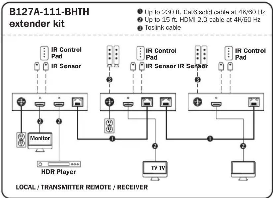
3) The installation diagram shows a B127A-111-BHTH unit.
4) External power is not required for remote receiver units due to Power over Cable (PoC) technology incorporated in the transmitter units.
Standard Extender Kit Installation
- Make sure all equipment in the installation—such as TVs, Blu-ray players and the transmitter—is powered OFF.
- Using an HDMI 2.0 cable (such as Tripp Lite P569-XXX-CERT or P568-XXX-2A Series cables), connect the HDMI source to the INPUT port on the local transmitter unit.
- Optional for B127A-111-BHTH: Using an HDMI 2.0 cable (such as Tripp Lite P569-XXX-CERT or P568-XXX-2A Series cables), connect a local monitor to the LOCALOUT port on the B127A-111-BHTH local transmitter unit.
- Using Cat6 cable, connect the RJ45 port on the local transmitter unit to the RJ45 port on the remote receiver unit.
- Using an HDMI 2.0 cable (such as Tripp Lite P569-XXX-CERT or P568-XXX-2A Series cables), connect the remote receiver or transceiver unit's HDMI port to a monitor.
- Turn on the power to your connected TVs/monitors. The LOCAL (orange) LED will illuminate to indicate the local port has been connected to a display.
Standard Extender Kit Installation
- Connect the external power supply to the transmitter. Plug it into an available wall outlet or a Tripp Lite surge protector, power distribution or uninterruptible power supply (UPS). The POWER (green) LED on the local transmitter unit will illuminate to indicate the unit is receiving power from the external power supply. The POWER (green) LED on the remote receiver unit will illuminate to indicate the unit is receiving power from the local transmitter unit through PoC technology.
- Turn on the power to the HDMI source. The OUTPUT (orange) LED on the local transmitter unit will illuminate to indicate a signal is being received from the source.
- The (orange) RJ45 LED will illuminate on both the local transmitter and remote receiver units to indicate a signal is being received from the source to display. The screen should now display on the connected monitor.
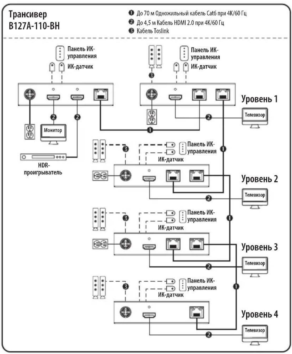
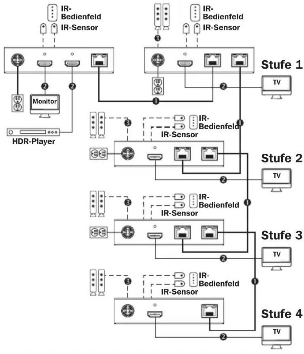
Transceiver Daisy-Chain Installation (B127A-110-BH only)
Notes:
1) Test to ensure the entire installation works properly before pulling cables through ceilings/walls.
2) To achieve maximum distance and performance, use 24 AWG solid wire Cat5e/6 cable. Using stranded wire Cat5e/6 cable or cable with a gauge (AWG) size higher than 24 AWG will result in shorter extension distance. Higher gauge cabling, such as 26 AWG, has a more limited transmission capability than lower gauge cabling. All Tripp Lite N202-Series Cat6 cables are made with 24 AWG solid wire cabling.
3) The installation diagram shows the B127A-111-BHTH and B17A-110-BH installation.
Transceiver Daisy-Chain Installation (B127A-110-BH only)
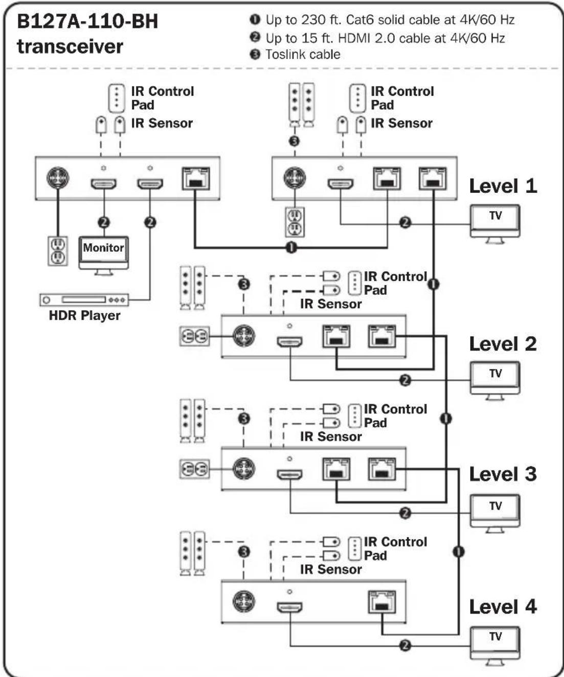
Transceiver Daisy-Chain Installation (B127A-110-BH only)
- Make sure all equipment in the installation—such as TVs, Blu-ray players and the transmitter—is powered OFF.
- Connect the HDMI source to the INPUT port on the B127A-111-BHTH using a Tripp Lite P568-Series HDMI Cable.
- Connect a local monitor to the LOCAL HDMI port using a Tripp Lite P568-Series HDMI Cable.
- Connect the external power supply to the local unit and plug it into a Tripp Lite surge protector, power distribution unit (PDU) or uninterruptible power supply (UPS). The green RJ45 LEDs will illuminate to indicate power is being received from the external power supply.
- Using Cat5e/6 cable, connect one of the RJ45 output ports on the local unit to the RJ45 input port on the B127A-110-BH transceiver unit.
- Connect a monitor to the HDMI OUTPUT port on the transceiver unit using a Tripp Lite P568-Series HDMI Cable.
- The green power LED and the green RJ45 LEDs on the transceiver will illuminate to indicate the unit is receiving power. Up to four units can be daisy-chained (three transceivers and one receiver). To connect additional transceiver units, proceed to step 8. To finish your installation with a B127A-110-BH unit, proceed to step 12.
Transceiver Daisy-Chain Installation (B127A-110-BH only)
- Using Cat5e/6 cable, connect the RJ45 OUTPUT port on the B127A-111-BHTH receiver unit to the RJ45 INPUT port on B127A-110-BH.
- Connect a monitor to the HDMI OUTPUT port on the B127A-110-BH that you just added using a Tripp Lite P568-Series HDMI Cable.
- Connect the external power supply to the B127A-110-BH and plug it into a Tripp Lite surge protector, power distribution unit (PDU) or uninterruptible power supply (UPS). The green power LED and the green RJ45 LEDs will illuminate to indicate the unit is receiving power.
- To add a second B127A-110-BH, repeat steps 8 through 10. To finish your installation with a B127A-110-BH, proceed to step 12.
- Using Cat5e/6 cable, connect the RJ45 OUTPUT port on the last B127A-110-BH to the RJ45 INPUT port.
- Connect a monitor to the HDMI OUTPUT port on the B127A-110-BH using a Tripp Lite P568-Series HDMI Cable.
- The green LED on the B127A-110-BH will illuminate to indicate the unit is receiving power from the previous transceiver. The orange LED will illuminate to indicate the unit is connected to a powered ON remote/repeater unit.
- Turn on the power to the HDMI source. The orange RJ45 LEDs on the local unit will illuminate to indicate a signal is being received from the source.
Transceiver Daisy-Chain Installation (B127A-110-BH only)
- If necessary, use the Equalization control on the remote/repeater unit(s) and remote receiver unit to adjust the video image.
- The maximum number of daisy chain layers is 4 for a total distance of 920 ft.
Note: An improper Equalization setting can cause the monitor not to display a picture at all. Try each Equalization setting until an acceptable picture is displayed.
USB/IR/Toslink Controls
The extender kit provides the following functional controls:
- USB 1.1 - One Micro-USB input at transmitter, dual USB-A outputs at receiver
- Bi-Directional IR - Dual 3.5 mm jacks at both the transmitter and receiver
- Toslink output at receiver and transceiver
(Optional) Connect the included IR-OUT cable to the transmitter unit's IR-OUT port. Place the sensor on the IR-OUT cable in an unobstructed area within clear view of the device being controlled. Then connect the included IR-IN cable to the receiver unit's IR-IN port. The IR-IN cable will communicate the desired command via the transmitter's IR-OUT cable.
Note: The IR-OUT cable receives the signal from the remote control and sends it to the device being controlled (e.g. Blu-ray player, etc.).
(Optional) With a user-supplied USB Micro-B cable (such as Tripp Lite U050-XXX Series USB cable), connect to the transmitter's Micro-B port. Then connect a keyboard and mouse to the available USB-A ports on the receiver unit.
(Optional) Using a Toslink cable (such as Tripp Lite A102-XXM Series cables), connect the Toslink cable to a set of speakers, an audio receiver or other audio system equipped with Toslink digital outputs.
Warranty and Product Registration
1-Year Limited Warranty
TRIPP LITE warrants its products to be free from defects in materials and workmanship for a period of one (1) year from the date of initial purchase. TRIPP LITE's obligation under this warranty is limited to repairing or replacing (at its sole option) any such defective products. To obtain service under this warranty, you must obtain a Returned Material Authorization (RMA) number from TRIPP LITE or an authorized TRIPP LITE service center. Products must be returned to TRIPP LITE or an authorized TRIPP LITE service center with transportation charges prepaid and must be accompanied by a brief description of the problem encountered and proof of date and place of purchase. This warranty does not apply to equipment which has been damaged by accident, negligence or misapplication or has been altered or modified in any way.
EXCEPT AS PROVIDED HEREIN, TRIPP LITE MAKES NO WARRANTYES, EXPRESS OR IMPLIED, INCLUDING WARRANTYES OF MERCHANTABILITY AND FITNESS FOR A PARTICULAR PURPOSE. Some states do not permit limitation or exclusion of implied warranties; therefore, the aforesaid limitation(s) or exclusion(s) may not apply to the purchaser.
EXCEPT AS PROVIDED ABOVE, IN NO EVENT WILL TRIPP LITE BE LIABLE FOR DIRECT, INDIRECT, SPECIAL, INCIDENTAL OR CONSEQUENTIAL DAMAGES ARISING OUT OF THE USE OF THIS PRODUCT, EVEN IF ADVISED OF THE POSSIBILITY OF SUCH DAMAGE. Specifically, TRIPP LITE is not liable for any costs, such as lost profits or revenue, loss of equipment, loss of use of equipment, loss of software, loss of data, costs of substitutes, claims by third parties, or otherwise.
PRODUCT REGISTRATION
Visit tripplite.com/warranty today to register your new Tripp Lite product. You'll be automatically entered into a drawing for a chance to win a FREE Tripp Lite product!*
- No purchase necessary. Void where prohibited. Some restrictions apply. See website for details.
Warranty and Product Registration
WEEE Compliance Information for Tripp Lite Customers and Recyclers (European Union)
Under the Waste Electrical and Electronic Equipment (WEEE) Directive and implementing regulations, when customers buy new electrical and electronic equipment from Tripp Lite they are entitled to:
- Send old equipment for recycling on a one-for-one, like-for-like basis (this varies depending on the country)
- Send the new equipment back for recycling when this ultimately becomes waste
WARNING
Use of this equipment in life support applications where failure of this equipment can reasonably be expected to cause the failure of the life support equipment or to significantly affect its safety or effectiveness is not recommended.
Tripp Lite has a policy of continuous improvement. Specifications are subject to change without notice. Photos and illustrations may differ slightly from actual products.


Manufacturing
1111 W. 35th Street, Chicago, IL 60609 USA · tripplite.com/support
20-10-008 93-3D27_ReVA
1111 W. 35th Street, Chicago, IL 60609 EE UU • triplite.com/support
1111 W. 35th Street, Chicago, IL 60609 EE UU • tripplite.com/support
20-10-008 93-3D27_ReVA
1111 W. 35th Street, Chicago, IL 60609 USA • triplite.com/support
1111 W. 35th Street, Chicago, IL 60609 USA • triplite.com/support
20-10-008 93-3D27_ReVA
PykoBODCTBO N0Ib30BaTeJia
KoMnJIeKtbl peTpaHcIaTOpOB HDMl chepe3 Cat6 n peTpaHcIaTOp (4K/60 T)
Mодениkomплесковpeетрансяторов:B127A-1A1-BHBH, B127A-1A1-BHPH,B127A-111-BHTH,B127A-110-BH Mодениpeетрансятopa:B127A-010-H
English 1 • Espanol 26 • Français 53 • Deutsch 105


PpOyKunBcuWcEoH KcNCTbA.
HDMI
HSHDSEPHTINMULTBDOATIMTRPA
1111 W. 35th Street, Chicago, IL 60609 USA - triplite.com/support
OxpanaTcA BTOpCKnM npaBOM © 2021 Tripp Lite. NepeneuTaKta Zanpeuaetca.
CopexmuoynakOBkn
Ha npuBeHbIX HnKe u3o6paXeHnX npeCTaBneHbI B03MOxHbI cNoCobI KpenJIeHH BxoJaXh B KOMnEKT MOHTaXHbIX KPOHtTeHOB dJa pa3NNUHbIX yCTaHOBOK.
Ipumeyaue. Ipubeehn Hxke Moden bp npedcmabena monbko b kaecme unnocmpauu. Baue u3denue moxem omnuambcna no homepy modenu, pa3mepy unu opuenmauu npmoB. BapuaHmbi MOhmaxa oduhakobblrae cx IP-Modyne.
HacteHHbIMoHTaX

TpaHcNBepoB (ToIbKO,IJIa MoI, B127A-110-BH)
YcTaHOBka Co 7IeNfoBbIM NOdknIOUyeHNMe TpaHCNBepOB (ToIbKO dIy MoI, B127A-110-BH)
- Y6eIITecb B TOM, qTO pHTaHne BCero 06OpyIOBaHnra (a nMeHHo TeNeBn3OpOB, npOIRpbIBaTeNei Blu-ray n nepedatTuHa) oTKIOueHo.
- Поdkлочи龟ctoуннHDMI-cnrgana Ko BXOДHOMY nopTu moуь B127A-111-BHTC nomoью HMI-ka6eЯ Tripp Lite cepu P568.
- Пордклочи Лokальнь монтор к порту LOCAL HDMI сnomоцью HDMI-ka6еля Tripp Lite cepи P568.
- Поdkлioчnte K lokaibHomу nepedaTchky BheuHn NCTOCHN PNTaHn, 3aTeM BknIOHTe ero B ceTeBOJ nIbTp, 6noK paCnpdeJeHn PNTaHn (PDU) nnn IcTOUHK 6ecnepe6oHoro nITaHn (N5Pi) Tripp Lite. HAnuNe nITaHn ot BHeuHero nCTOChnKa 6ydet OTO6paXaTBcR CBeToDIOndhIMn INdNKATopamn RJ45 3eNeHOrO cBeta.
- CoeINHnTe OINH n3 BbIXoHbIX nopToB RJ45 loKaIbHo rO MoDyIa CBXoHNbIM nopToM RJ45 TpaHcNBePa B127A-110-BH npn nomoi Ka6eIa Cat5e/6.
- Пордклочи монитор К порту HDMI OUTPUT (BblXODHDMI) Трансubера спомоцью HDMI-kaбеля Tripp Lite cepи P568.
- Hanuhe nnta Hra TpaHcBepa OTo6pKaetcraero CBeToIOHbIMn INHdkaTOpamn Power ("PiTaHne") n RJ45 3eIeHoro zBaTe. PpeymatPnaBaeTc B03MOxHOCTb IneΦOBOro noKluoyehn Do YeTbipex MoUyne (Tpex TpaHCNBepOB n Ondoro npneMHka).ДЯ noKluoyehn DoonHHTeNbHbIX TpaHCNBepOB NepeiNeTe K wary 8.ДЯ 3abepseHn KOMNKeTauCn CBoe yCTaHOBKn MoUyEm B127A-110-BH nepeiDte K wary 12.
YcTaHOBKa co ⅢeBbIM NOdkIIOUeHNEM
TpaHcNBepoB (ToIbKO,IJIa MoI, B127A-110-BH)
- CoeMHnTe npT RJ45 OUTPUT (BbIXOД RJ45) npHemnka B127A-111-BHTC npToM RJ45 INPUT (BXOD RJ45) TpaHcHbepa B127A-110-BH npn noMoOn Ka6eJr Cat5e/6.
- Пождклочи монитор к порту HDMI OUTPUT (BbIXODHDMI) только что установленно Трансubера B127A-110-BH с пошью HDMI-ka6еля Tripp Lite cepи P568.
- Поdkлочи К Трансьеру B127A-110-BH Вheшни NGTOUHK NITAHNY, 3aTeM BKIOUHTe erO B ceteBOJ FOJIbTp, 6NoK paCnpedelenHry NITAHNY (PDU) nIINCTOUYK 6ecpe6oHOrO pHTAHNY (N5П) Tripp Lite. HAnuHne pHTAHNY MOnyJIy 6yIeT OTo6paxaTbcra CBETODNOHbIMn INHdNKaTopamn Power ("PITAHNE") u RJ45 3eNeHOrO uBeta.
- Дя подклоченя доронитьногу TrpaHcNBepa B127A-110-BH noBtopuTe warr 8-10. Дя заBERSEHЯ KOMпeКТaцIN CBoe yCTaHOBk moDyIeM B127A-110-BH nepeiDHTe K Wary 12.
- CoeHnHTe nopT RJ45 OUTPUT (BblXOД RJ45) nocHeJero TpaHcNBepa B127A-110-BH c npToM RJ45 INPUT (BXOД RJ45) npn nomoNs Ka6eNa Cat5e/6.
- ПоdkлочиMe MOHITOP K npoty HDMI OUTPUT (BbIXOД HDMI) petpahcnaTopa B127A-110-BH c nomoobu HDMI-ka6eTraPp Lite cepn P568.
- Hanuhe nntaHnMoDyIOn ot npedbIduyUero TpaHcNBepa OTo6paXaeTcBcTeODnOdbIM HndKATOpOM 3eJeHoro UBeTa Ha yctpoiCTBe B127A-110-BH. IodKnIOueHne daHnro MoDyIg K 3aNTaHHomy ydaJIeHHOMy/peTpaHcNauOHHomMy MOnyIO OTo6paXaeTcCBcTeODnOdbIM HndKATOpOM opAHxkeBOrO UBeTa.
- BkIIOUHTe nITaHne nCTOuHnka HDMl-cnHaJa. IOnyueHne cunHana ot nCToUHnka loKaJIbHbIM MoIyIeM OTo6paJxAetc CBETOAnOdHbIMn INHdkaTOpamr RJ45 opAHKeBOrO uBeTa.
YcTaHOBka Co 7IeNfoBbIM NOdknIOUyeHNMe TpaHCNBepOB (ToIbKO dIy MoI, B127A-110-BH)
- При Heo6xOДmOCTn BocnoIb3yITeCb эКВаиЗeрOM ydaJIeHOrO(-bIX) moIyIeN/ NOBTOpITeIa(-eI) n ydaJIeHHO rPnEIMHO rMOyIa Ira KOppeKcIIu KaueCTBa BIndeOn3O6paJxKeHry.
- MaKcImaJIbHoe YnCNo yPoBHei IJneIfoBOro NODKnIOueHnra: 4. CymMapHaJa DaJIbHOCTb peTpaHCJIaCnU: 280 M.
Ipumeyane. HenpaunbnaH aHcmpouka 3Kbana3epa moKem npuecmu K noHOMy omycmcbuO u3o6paKeHnHa MoHumope. NOnbmaumecb doobmbcra npabunbHO Hacmpouku KaXdo20 u3 eMeHmoB 3Kbana3epa do nolyeHn npueMeMozo KauecmBa u3o6paKeHn.
UnpaBnenne uepe3 USB/IK/Toslink
KOMnJIeKT petpaHcIaTopa oBeCneuBaet cIeIyUoIe yHKUOHaJIbHbIe 3JIemEHTbl ynpabLeHn:
USB 1.1 - OdnBxoD Micro-USB ha nepaTnke, Dba BbixoJa USB-A Ha npneMnke
-ДынларпенныИК - по дba pa3bema 3.5mm Ha nepedatunkeи премнke
BbIXoToslinkHa npneMnke n nepedatunke
(Heo6aTeBHO) BCTaBbTe BbIXOHOH IK-Ka6eB (IR-OUT) n3 KOMnEKeTb Nopr IR-OUT nepeDaTuKHa. YCTaHOBITE DaTUnK Ha Ka6eB IR-OUT B CBO6OHNOM OT npenrCTBm MeCte TaKIM O6pa30M, UTO6bl ynpabNaeMoE yCTpoiCTBO HxOAnIOCb B npedeJax BUNMOCTN. 3aTeM BCTaBbTe BXOHOH IK-Ka6eB (IR-IN) n3 KOMnEKeTb Nopr IR-IN npneMnKa. Ka6eB IR-IN 6ydt nepeDaBaTb HxKnble KOMaHdbI uep3 Ka6eB IR-OUT nepeDaTuKHa. IpumeyAue. Ka6eB IR-OUT npuHMaem cuzhan ducmauOnHo2o ynpaBneHua u nepedaem e2o Ha ynpabNaeMoE ycmpoucMbO (Hanpumep, npou2pbiamenBlu-ray u np.).
(Heo6aTeNbHo) C nOmoIbIO Ka6eNa USB Micro-B, He BxOJaIeRo B KOMnJIeK T NOCTaBKn (HapnIeMep, USB-Ka6eNa Tripp Lite cepuu U050-XXX), BblOnHnTe noDKIoueHne K npOpTu Micro-B nepeDaTUnKa. 3aTeM noDknOHTe KnaBnAtpy uMbIb K CBO6OdHbIM nopTaM USB-A npnemHnka.
(Heo6a3aTeIbHo) PoIcoeINHITe Ka6eN Toslink (HaNPmep, Ka6eN Tripp Lite cepn A102-XXM) K akyctnuecko cnCTeme, ayuOnpneMHnky nIn dpyro ayuNoCnCTeme, ochaueHHo uΦpoBbIM N BixOdaMn Toslink.
TapaHTnI npErnctpaunI3denn
OrpaHnueHHa rapaHTna cpoKOM 1 roD
KomnaHnTRIPP LITE rapaHTpyeOTcYCTBNE DeEeKTOMaTePnAIOB n3rOToBHeHn B TeueHne OJHO (1) rOda c MOpMeHTa nepBOHaaybHoN NOKVKN.
06a3aTeNbCTBa KOMnAHn TRIPP LITE no HactoIeI rapaHTm OrpaHnUbaOTc peMOHTom nI 3aMeHO (no ee eHNOHCHOMy yCMOTpeHIO) IIObIX TaKHX DeFeKTHbIX N3dJI. DInI NOUYeHnY yCNYr No DaHHoR rapaHTn HEOxOIMNoNtBHomeRrtdedMaterialAorhization (RMA — pa3peSeHne Ha BO3BpTaMATEPNAIOB) OT KOMnAHn TRIPP LITE nIe ee ABTOZOBAHBO CepBnCHOrO cHTpa. N3dJIra DOJXHBi 6bITb BO3BpaSeHb B KOMnAHn TRIPP LITE nIe ABTOZOBAHbI CepBnCHbI cHTp TRIPP LITE c npEOnlato TpaHCnOpTbXb paXoDOb IN COPOBQDaTBCRA KpATKIM ONCAHEm BO3HKWe pO6JIeMy IN DOKUMENTOM, NOITBepXdaIOUIm DaTy IMcTo erO npio6peTeHn. DeIcTBHe hactoIe rapaHTm He paCnpocTpaHReTc Ha O6OpuOBAHme, NOBpeXdeHHOe B pe3yIbTaTe abapIN, He6peXHOrO o6paSeHn IIN HEPaBUNbHOrO NCIOB3OBHnA, a TaKKe BVIDON3MeHeHHOe KaKIM 6bl To HN 6blIO 6pbzOM.
3A NCKJIIOUCHHEM IPEYCMOTPEHHbIX 3DECb CJUYAEB KOMIIAHNTRIPP LITE HE IPEIOCTABJRET KAKNX- JIN60 RAHBIX INI IOIPA3YMEBAEMbIX TAPAHNTI, BKJIIOUAY TAPAHNTI KOMMEPUECKO IPIROHOCTNI IPIROJOHOCTIN JIA KAKOI-JIN60 KOHKPETHOIJI. B HeKOToBPbX Wtatax/TOcydApCTBax OrpaHnueHne INI NCKJIIOUCHHe IIOp4ZMeBaEMbIX rapaHTN He DONYCAeTc; CIEIOBaTeNbHO, BblweyKa3aHHO(-bie) OrpaHnueHne(--) INI NCKJIIOUCHHe(-) MOrYT He paCnpoCTpaHrTaBC Ha NOKyNaTeJI.
3A NCKJIIOUCHHEM IPEDYMOTPEHHbIX BbIIE CNYAEB KOMNAHRA TRIPP LITE HN INPNI KAKNX OBCTOReTJIbCTBAX HE HECET OTBETCTBEHHOCTN 3A INPMABIE, KOCBEHNbIE, CNYAHbIE ININIO5OHyBIE YbItKN JIN60YbItKN, ONPEDEJREMBIE OCOBbIMN OCBSTORTEbCTBAMN, BO3HNKAIOUIE B CBA3N CNCIOJIb3OBAHNEIM DAHHORO IN3JEINIA, DAXE B CNYAEE INHOOPMIMPOBAHNA O BO3MOXHOCTN HACTYNLEHNA TAKNX YbItKOB. B uactHOCTN, KOMNAHRA TRPP LITE He Hecet OTBETCTBEHHoCTN 3a KaKne-In6o IN3depKKn, TaKne KaK yNuueHbIe pIn6blnn INI doxobbl, nOtepa o6OpyOBaHNA, nOtepa Bo3MOXHOCTN INCNOb3OBAHNA o6OpyOBaHNA, nOtepa npOrpAMMHO RObcneueHNA, nOtepa DaHHbIX, paCXOBbl Ha 3aMeHHTEN, UpeYIMPOBaHNe PpeTeH3m TpeTBHX IMI INP.
TapaHTnI npErnctpaZnI n3dJIIna
HΦopMaζη no BbIOnHeHt Tpe6oBaHn ΠupeKTHBbl WEEE nIpoKynaTeIe I nepepa60TcIKOB npOdyKznn KOMNaHm Tripp Lite (AByIooxXpe3nIeHTAmE Ebponeckoro co103a)

Cornacno noIonoJHnIaM DnpeKtNbbl 6 oyTuIN3aun OTxOIOB 3NeKtpueckoro n 3NeKtpoHHORO
obopydOBaHna (WEEE) u nCpONHITeINbHbIX paCnpopJxHeHn Ioo ee npImMeHnIO, npn NOKynKe
noTpe6HtEAMn HOBOrO 3NeKtpueckoro Hnn 3NeKtpoHHORO obopydOBaHn npOn3BOcCTBa KOMnAHn
Tripp Lite onH nOnyauIOT npABo Ha:
- PpOdaJx cyaporo 06OpuyoBaHnno npHnunny "OuH 3a OUnH" n/Unn Ha KKBuaeHTHO OHOBE (B 3aBNCIMOCn OT KOHKpeTHOH CTpaHbI)
- Otnpabky HOBOr o6OpyDObaHnHa npepea60Ku nocle oKOnHauTeBHoB BbIpa60Kn erO pecypca
BHUMAHNE!
He pekomehnyetcnaonb3oBAHne daHHoro 60pyoBaHnB CnCTeMaX Xn3Heo6cepeHn, rIe erO BbIXoN 3ctpo npednoJoxntbHO MoKET npIBeTn K nepe6oam B pa6ote 60pyoBaHnXn3Heo6cepeHn nnB 3NaHTbHo Mepe CHN3NTb ero 6e3oNaChOCTb nn EeEeKtNBHOCTb.
KomnaHn Tripp Lite noctoHHo COBepseHCTBye T CBOIO npOdyKunio. B CBa3N C 3TNM BO3MOxHO u3MeHeHneTexHuecknx XapaKTepncTik Be3 npEaBapntelbHoro yBeDOMLeHnA. BHeuH N Bn peaIbHbIX u3DeJIM MOKeT HeKoJIbKO OTnUaTbCt O TnpdCTaBHeHHoro Ha oToTpaqnx H nllIOCTpaunx.


POMPHORIN NUCLEOTIDE KINCTCBS
1111 W. 35th Street, Chicago, IL 60609 USA · triplite.com/support
104
20-10-008 93-3D27_ReVA
Bedienungsanleitung
Manufacturing Excellence.
1111 W. 35th Street, Chicago, IL 60609 USA • triplite.com/support
B127A-110-BH Transceiver
1111 W. 35th Street, Chicago, IL 60609 USA · tripplite.com/support
132
20-10-008 93-3D27_RevA