NSSG16D2 - Smart Home Tripp Lite - Free user manual and instructions
Find the device manual for free NSSG16D2 Tripp Lite in PDF.

User questions about NSSG16D2 Tripp Lite
0 question about this device. Answer the ones you know or ask your own.
Ask a new question about this device
Download the instructions for your Smart Home in PDF format for free! Find your manual NSSG16D2 - Tripp Lite and take your electronic device back in hand. On this page are published all the documents necessary for the use of your device. NSSG16D2 by Tripp Lite.
USER MANUAL NSSG16D2 Tripp Lite
Rackmount Managed Network Switch with
Built-in PDU and
isobar® Surge Protection
Models: NSS-G16D2, NSS-G24D2
(Series Number: AG-014D)
Español 9 • Français 17
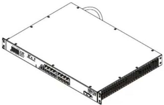
natural_image
Illustration of a rectangular electronic device with ports and connectors (no text or symbols visible)PROTECT YOUR INVESTMENT!
Register your product for quicker service and ultimate peace of mind.
You could also win an ISOBAR6ULTRA surge protector— a \$100 value!

text_image
QR code image containing encoded data, no visible human-readable textwww.tripplite.com/warranty

text_image
TRIPP·LITE
1111 W. 35th Street, Chicago, IL 60609 USA • www.tripplite.com/support
Copyright © 2016 Tripp Lite. All rights reserved.
Important Safety Instructions

SAVE THESE INSTRUCTIONS!
This manual contains important instructions and warnings that should be followed during the installation, operation and storage of this Tripp Lite product. Failure to heed these warnings may affect your warranty.
PDU/Switch Location Warnings
- The switch is designed for indoor use only, in a controlled environment, away from excess moisture, temperature extremes, conductive contaminants, dust or direct sunlight.
- For best performance, maintain an indoor temperature between 32°F and 104°F (0°C and 40°C) with relative humidity between 10% and 90% (non-condensing).
- Install in accordance with National Electrical Code standards. Be sure to use the proper overcurrent protection for the installation in accordance with the plug/equipment rating.
- Leave adequate space around all sides of the switch for proper ventilation.
- Keep the switch away from high-frequency, strong-current devices (e.g., radio transmitting stations, transmitters and broadband amplifiers).
- Use electromagnetic shielding (if required).
- For rackmount configuration, ensure both the rack and switch are properly grounded.
- If the switch is not rack mounted, securely place it on a sturdy, flat surface.
- The electrical outlets supplying power to the equipment should be installed near the equipment and easily accessible.
- Improper installation can cause product damage that is not covered by the warranty.
- Do not expose the switch's connected networking cables to outdoor elements.
- CAUTION – Do not install this device if there is not at least 30 feet (10 meters) or more of wire between the electrical outlet and the electrical service panel.
- Do not use this product near water (e.g., in a wet basement, or near a swimming pool).
PDU/Switch Connection Warnings
- Use of this equipment in life support applications where failure of this equipment can reasonably be expected to cause the failure of the life support equipment or to significantly affect its safety or effectiveness is not recommended. Do not use this equipment in the presence of a flammable anesthetic mixture with air, oxygen or nitrous oxide.
- Keep the switch's input power off during installation.
- Use only the power cord that came included with the switch.
- Make sure the power supply voltage matches the specifications indicated on the switch.
- The total power requirement for equipment connected to the switch must not exceed the maximum load rating for the PDU's circuit breaker.
- Do not connect the switch to an ungrounded outlet or to extension cords or adapters that eliminate the connection to ground.
- Do not drill into or attempt to open any part of the switch housing. There are no user-serviceable parts inside.
- Do not attempt to modify the switch, including the input plugs and power cables.
- Do not attempt to use the switch if any part of it becomes damaged.
- Make sure network cables are properly seated. A clicking sound will be made when a cable is installed correctly.
- If the power cord is damaged, do not attempt to connect the switch. Contact a Tripp Lite Service Representative for assistance.
- Never attempt to install or use the switch during a thunderstorm.
Accessing the Management Configuration Interface
After powering the switch for the first time, the Network Smart Switch can be configured using a Web browser. To access the switch, the management computer and the switch must be set to the same subnet. The IP address of the management computer must be configured manually. The switch's default IP address is 192.168.1.200 and the default subnet mask is 255.255.255.0.
The Network Smart Switch contains software for viewing, changing and monitoring how it works. This management software is not required for the switch to function. The ports can be used without the management software. However, the management software enables the setup of VLAN, Trunking and additional features. The use of these features can also improve the efficiency of the switch, which results in the improvement of its overall performance as well as the performance of the network.
For more information about configuring the switch, visit www.tripplite.com to view the Network Smart Switch Web Configuration Guide.
Product Features
NSS-G16D2
Front Panel:
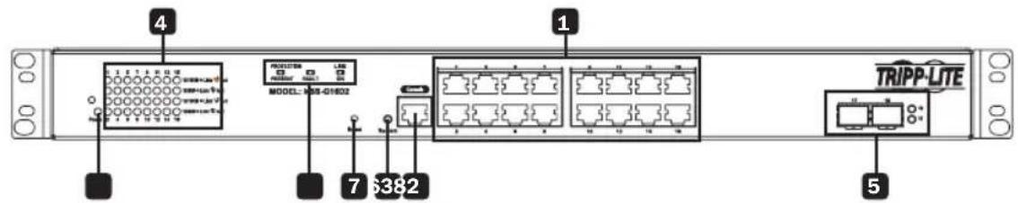
text_image
4 MODEL: M-15-G1802 7 6382 1 TRIPP-LITE 5Rear Panel:
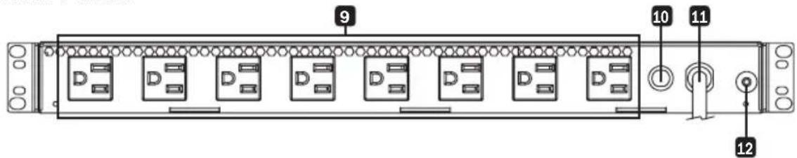
text_image
9 10 11 121 Gigabit Ethernet Ports: These 16 twisted-pair RJ45 ports support auto-negotiable 10/100/1000 Mbps and auto MDI/MDIX cross-over detection functions for true “plug and play” capability.
Note: Not compatible with PoE (Power over Ethernet) applications.
2 Power ON/OFF LED: An LED illuminates to indicate the switch is receiving power.
3 System Status LED: This LED will illuminate solid green when the system is loading and will blink to indicate the system is ready.
4 Port Status LEDs: Of these 32 LEDs, 16 illuminate orange for 10/100 Mbps LEDs connection status and blink to indicate activity on each port. When the switch discovers a 1000 Mbps connection, the other 16 LEDs will illuminate green for connection status and blink to indicate activity on each port.
5 MiniGBIC: The MiniGBIC (gigabit interface converter) ports are connection points for MiniGBIC modules so the switch can uplink to other switches using optical fiber. When the MiniGBIC ports are active, the LEDs adjacent to the ports will react to interface traffic.
Product Features
6 Console Port: This RJ45 port is used for command line access to the switch.
7 Reset Button: Pressing the reset button performs a factory reset.
Note: This button is semi-recessed and will need to be pressed with a small object, such as a paperclip.
8 AC Power Diagnostic LEDs: The three LEDs on the front panel show current power conditions (left to right):
Protection Present (Green LED): Indicates surge-suppression components are intact and providing full protection against spikes and surges. This LED should illuminate any time the unit is plugged in and power is present. If the Protection Present LED does not illuminate, some of the surge suppression components are not functioning and the unit should be returned for repair as soon as possible. You may still use the unit; however, connected equipment will be protected from spikes and surges at a lesser level than normal.
Fault (Red LED)*: Indicates a wiring fault has been detected. If this LED illuminates at any time while the unit is plugged in, the fault should be repaired by a qualified electrician as soon as possible. This LED indicates the phases are reversed, ground is missing or some other sort of wiring error exists in the circuit the unit is plugged into. The Line Fault detector circuitry will identify most common wiring faults, but will not necessarily detect every possible type of fault.
Line OK (Green LED): Indicates that nominal AC power is present with no wiring faults detected. When this LED is illuminated, AC power is safe for connected equipment.
9 NEMA 5-15R Outlets: This switch includes 8 NEMA 5-15R receptacles.
10 Circuit Breaker: If the current drawn by the equipment connected to the Smart Switch outlets exceeds the Maximum Load Rating, the 12A thermal circuit breaker will trip to prevent possible damage and its plunger will pop up. If this happens, disconnect excess equipment and allow the breaker to cool at least one minute before depressing the plunger to reset the unit.
11 AC Input: Permanently attached input cord with a NEMA 5-15P input plug.
12 Grounding Lug: Use this screw to connect your switch to ground.
* If the Line Fault (Red LED) indicator illuminates, carefully check the AC receptacle the unit is plugged into. The receptacle must be tight and securely grounded. A loose AC receptacle may cause the Line Fault LED to illuminate. The Red LED indicates the presence of a wiring fault, but does not indicate the exact nature of the fault. Only qualified electricians should make necessary outlet repairs.
If the Line Fault indicator illuminates and power is not present at the outlets, the PDU's surge-suppression components have been compromised as a result of surge damage. For service, contact Tripp Lite Customer Support at www.tripplite.com/support to remedy the problem or receive instructions about return, repair or exchange.
Product Features
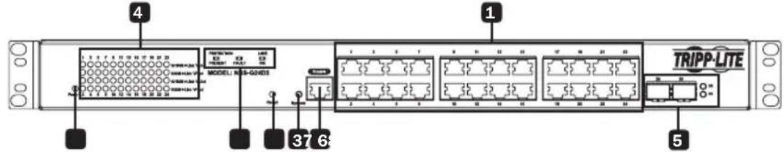
NSS-G24D2
Front Panel:
text_image
4 1 MODELI: M-3-GND3 37 6 5 TRIPP-LITERear Panel:
text_image
Rear Panel. 9 10 11 121 Gigabit Ethernet Ports: These 24 twisted-pair RJ45 ports support auto-negotiable 10/100/1000 Mbps and auto MDI/MDIX cross-over detection functions for true “plug and play” capability.
Note: Not compatible with PoE (Power over Ethernet) applications.
2 Power ON/OFF LED: An LED illuminates to indicate the switch is receiving power.
3 System Status LED: This LED will illuminate solid green when the system is loading and will blink to indicate the system is ready.
4 Port Status LEDs: Of these 48 LEDs, 24 illuminate orange for 10/100 Mbps LEDs connection status and blink to indicate activity on each port. When the switch discovers a 1000 Mbps connection, the other 24 LEDs will illuminate green for connection status and blink to indicate activity on each port.
5 MiniGBIC: The MiniGBIC (gigabit interface converter) ports are connection points for MiniGBIC modules, so the switch can uplink to other switches using optical fiber. When the MiniGBIC ports are active, the LEDs adjacent to the ports will react to interface traffic.
6 Console Port: This RJ45 port is used for command line access to the switch.
7 Reset Button: Pressing the reset button performs a factory reset.
Note: This button is semi-recessed and will need to be pressed with a small object, such as a paperclip.
Product Features
8 AC Power Diagnostic LEDs: The three LEDs on the front panel show current power conditions (left to right):
Protection Present (Green LED): Indicates surge-suppression components are intact and providing full protection against spikes and surges. This LED should illuminate any time the unit is plugged in and power is present. If the Protection Present LED does not illuminate, some of the surge suppression components are not functioning and the unit should be returned for repair as soon as possible. You may still use the unit; however, connected equipment will be protected from spikes and surges at a lesser level than normal.
Fault (Red LED)*: Indicates a wiring fault has been detected. If this LED illuminates at any time while the unit is plugged in, the fault should be repaired by a qualified electrician as soon as possible. This LED indicates the phases are reversed, ground is missing or some other sort of wiring error exists in the circuit the unit is plugged into. The Line Fault detector circuitry will identify most common wiring faults, but will not necessarily detect every possible type of fault.
Line OK (Green LED): Indicates that nominal AC power is present with no wiring faults detected. When this LED is illuminated, AC power is safe for connected equipment.
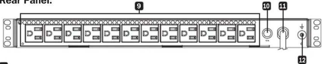
9 NEMA 5-15R Outlets: This switch includes 12 NEMA 5-15R receptacles.
10 Circuit Breaker: If the current drawn by the equipment connected to the Smart Switch outlets exceeds the Maximum Load Rating, the 12A thermal circuit breaker will trip to prevent possible damage and its plunger will pop up. If this happens, disconnect excess equipment and allow the breaker to cool at least one minute before depressing the plunger to reset the unit.
11 AC Input: Permanently attached input cord with a NEMA 5-15P input plug.
12 Grounding Lug: Use this screw to connect your switch to ground.
* If the Line Fault (Red LED) indicator illuminates, carefully check the AC receptacle the unit is plugged into. The receptacle must be tight and securely grounded. A loose AC receptacle may cause the Line Fault LED to illuminate. The Red LED indicates the presence of a wiring fault, but does not indicate the exact nature of the fault. Only qualified electricians should make necessary outlet repairs.
If the Line Fault indicator illuminates and power is not present at the outlets, the PDU's surge-suppression components have been compromised as a result of surge damage. For service, contact Tripp Lite Customer Support at www.tripplite.com/support to remedy the problem or receive instructions about return, repair or exchange.
Installation
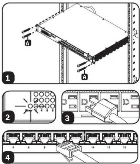
1U Rackmount Installation
1 Mount the switch using four user-supplied rackmount screws A. The user must determine the fitness of the rackmount screws to hold the unit in the rack before installation.
2 Connect the switch to a properly grounded outlet. The POWER LED will illuminate when the switch turns on.
3 Connect equipment to the PDU outlets. Make sure the load connected does not exceed the PDU's circuit breaker rating.
4 Connect network cables to the network switch.
Warranty and Product Registration
5-Year Limited Warranty
TRIPP LITE warrants its products to be free from defects in materials and workmanship for a period of five (5) years from the date of initial purchase. TRIPP LITE's obligation under this warranty is limited to repairing or replacing (at its sole option) any such defective products. To obtain service under this warranty, you must obtain a Returned Material Authorization (RMA) number from TRIPP LITE or an authorized TRIPP LITE service center. Products must be returned to TRIPP LITE or an authorized TRIPP LITE service center with transportation charges prepaid and must be accompanied by a brief description of the problem encountered and proof of date and place of purchase. This warranty does not apply to equipment which has been damaged by accident, negligence or misapplication or has been altered or modified in any way.
EXCEPT AS PROVIDED HEREIN, TRIPP LITE MAKES NO WARRANTIES, EXPRESS OR IMPLIED, INCLUDING WARRANTIES OF MERCHANTABILITY AND FITNESS FOR A PARTICULAR PURPOSE. Some states do not permit limitation or exclusion of implied warranties; therefore, the aforesaid limitation(s) or exclusion(s) may not apply to the purchaser.
EXCEPT AS PROVIDED ABOVE, IN NO EVENT WILL TRIPP LITE BE LIABLE FOR DIRECT, INDIRECT, SPECIAL, INCIDENTAL OR CONSEQUENTIAL DAMAGES ARISING OUT OF THE USE OF THIS PRODUCT, EVEN IF ADVISED OF THE POSSIBILITY OF SUCH DAMAGE. Specifically, TRIPP LITE is not liable for any costs, such as lost profits or revenue, loss of equipment, loss of use of equipment, loss of software, loss of data, costs of substitutes, claims by third parties, or otherwise.
PRODUCT REGISTRATION
Visit www.triplite.com/warranty today to register your new Tripp Lite product. You'll be automatically entered into a drawing for a chance to win a FREE Tripp Lite product!*
* No purchase necessary. Void where prohibited. Some restrictions apply. See website for details.
Regulatory Compliance Identification Numbers
For the purpose of regulatory compliance certifications and identification, your Tripp Lite product has been assigned a unique series number. The series number can be found on the product nameplate label, along with all required approval markings and information. When requesting compliance information for this product, always refer to the series number. The series number should not be confused with the marketing name or model number of the product.
FCC Notice, Class A
This device complies with part 15 of the FCC Rules. Operation is subject to the following two conditions: (1) This device may not cause harmful interference, and (2) this device must accept any interference received, including interference that may cause undesired operation.
Note: This equipment has been tested and found to comply with the limits for a Class A digital device, pursuant to part 15 of the FCC Rules. These limits are designed to provide reasonable protection against harmful interference when the equipment is operated in a commercial environment. This equipment generates, uses, and can radiate radio frequency energy and, if not installed and used in accordance with the instruction manual, may cause harmful interference to radio communications. Operation of this equipment in a residential area is likely to cause harmful interference in which case the user will be required to correct the interference at his own expense. The user must use shielded cables and connectors with this equipment. Any changes or modifications to this equipment not expressly approved by Tripp Lite could void the user's authority to operate this equipment.
Tripp Lite has a policy of continuous improvement. Specifications are subject to change without notice.

text_image
TRIPP·LITE
1111 W. 35th Street, Chicago, IL 60609 USA • www.tripplite.com/support
natural_image
Isometric line drawing of a server rack unit with ports and connectors (no text or symbols)
text_image
TRIPP·LITE
1111 W. 35th Street, Chicago, IL 60609 EE. UU. • www.tripplite.com/support
text_image
Diagram showing two electrical switch configurations: one with a grid and pin layout, the other with a terminal block labeled D.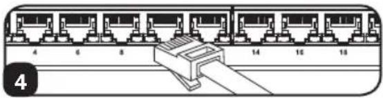
natural_image
Diagram of a 14-pin Ethernet connector with pin numbering (no text or symbols on the diagram itself)Garantía
natural_image
Isometric line drawing of a server rack unit with ports and connectors (no text or symbols)
text_image
TRIPP·LITE
Manufacturing Excellence
1111 W. 35th Street, Chicago, IL 60609 USA • www.tripplite.com/support
CONSERVEZ CES INSTRUCTIONS!
text_image
Diagram showing two electrical switch panel configurations with labeled terminals and a close-up of the internal circuit.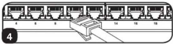
natural_image
Diagram of a 16-pin Ethernet connector with pin numbering (4 to 18) and a central connector (no text or symbols on the diagram itself)Garantie
1111 W. 35th Street, Chicago, IL 60609 USA • www.tripplite.com/support