GMME600X6 - AV receiver PIONEER - Free user manual and instructions
Find the device manual for free GMME600X6 PIONEER in PDF.
| Product Type | 6-Channel Car Audio Amplifier |
| Brand | Pioneer |
| Model | GMME600X6 |
| Category | Audio-Video Receiver (Amplifier) |
| Power Supply | 12 V DC (vehicle) |
| Output Power | 6 × 100 W RMS (under 4 Ω, 1% THD) |
| Speaker Impedance | 4 Ω (2 Ω stable in bridged mode) |
| Frequency Response | 10 Hz - 50 kHz (±1 dB) |
| Signal-to-Noise Ratio | > 100 dB |
| Total Harmonic Distortion | < 0.05 % |
| Inputs | 6 pairs RCA (line), speaker level input |
| Outputs | Screw terminals for 6 channels |
| Filters | Adjustable high-pass filter (HPF) and low-pass filter (LPF) |
| Special Features | Input mode selection (2CH/4CH/6CH), adjustable gain, thermal and short-circuit protection |
| Dimensions (W × D × H) | 300 × 200 × 60 mm |
| Weight | 2.0 kg |
| Care and Cleaning | Dust with a dry cloth; avoid any contact with water |
| Safety | Protection against polarity reversal, overheating, and short circuits |
| Spare Parts and Repairability | Contact Pioneer after-sales service; do not disassemble yourself |
| General Information | Manual available free as PDF at notice-facile.com |
Frequently Asked Questions - GMME600X6 PIONEER
User questions about GMME600X6 PIONEER
0 question about this device. Answer the ones you know or ask your own.
Ask a new question about this device
Download the instructions for your AV receiver in PDF format for free! Find your manual GMME600X6 - PIONEER and take your electronic device back in hand. On this page are published all the documents necessary for the use of your device. GMME600X6 by PIONEER.
USER MANUAL GMME600X6 PIONEER
PIONEER ELECTRONICS (WAL) INC.
R.O. Box 510, Long Beach, California 9080-1510, U.S.A.
PIONEER EUROPE N
Bavari (89), Bexkaylan 1,5-32/2024, Bajari/Bogur
POWER ELECTRONICS ASIA/CENTURE PTE. LTD
2 John Shang Bond, 407-1, Sagazav 18/24
(4) 12-09/2017
5.000.000.000.000.000.000.000.
TEL: 021-7896 5399
The following table is in English:
Oil Emissions in Capex/Box, W/O, N.P. 11/02
(2) 10:00:00
使用教学全部
台北市西溪區光路407號3樓
电话:010-632-825-7241
盈得元时长外高值506995倍
电话:010-28495465
6.2017年1月1日
(KNZ200)
-A:000635-GL-A-UC
Before you start
Thank you for purchasing this PIONEER
product
In the use of a system, please read into
17.4.20. 18.3.20. 19.3.20. 20.3.20.
WARNING COCAUTIONS
(https://doi.org/10.10345678)
the place is the source of
Information to User
4.2.10.1.1
The following table provides the data for
10.5.2 报告期末余额
Note
This eq. is not has been tested and found
to comply with the limit for a class 2 of a
[...] risks are designed to provide recomp-
in a resident of install sheet. Unip. eq. 139-1
Generics, use and can reduce red dye
couch.html.1 min source: F and non-
ricals. However, there is no purp#ge
reception, which can be determined by
- mng the equipment off and on the user's
by one time of the following no records:
Reorient release to receiving
e tonne
increase the separation between the
(2017年6月1日)
what is could differ from that to
Able the movement is more active.
- 2017年1月1日
FEDERAL COMMUNICATIONS
COMMISSIONS SUPPLIER'S DECLARATION
CFLCON-CHINI Part of the 100% service
SALME000
Responsible Party Name: PIONEER
After-sales service for
Pioneer products
Please contact the author and Florzer dealer
from which you purchase this author an
- Traced power service company for the
The part of the company of the parent company
2.1.1.
Do not ship your unit in for repair
without contacting Pioneer first.
UHEX GATE WINDER & RETURN AUTHORITY number will be refused.
USA & CANADA
Flower (200x) 5kg
CUSTOMED SO TOX LEVEL OF
www.Bank.CA0001260153
5042 1404
(No text)
For warranty information on a case see the
Bed Asbury Steel Includes With a unit
Visit our website
https://www.pinoeelectronics.com/PILSA/
Canada:
https://www.picemure.schron.co.jp/OCEN
• Loss of loss to the updates such as
• Reqs ester product
- 2018年1月1日
nions, service information and much more
The Safety of Your Ears is in
Your Hands
Get the real part of the company in place
-
-
-
-
-
-
-
-
-
-
-
-
-
-
-
-
-
-
-
-
-
-
-
-
-
-
-
-
-
-
-
-
-
-
-
-
-
-
-
-
-
-
-
-
-
-
-
-
-
-
-
-
-
-
-
-
-
-
-
-
-
-
-
-
-
-
-
-
-
-
-
-
-
-
-
-
-
-
-
-
-
-
-
-
-
-
-
-
-
-
-
-
-
-
-
-
-
- 99.
-
-
-
-
-
-
-
-
-
-
-
-
-
-
-
-
-
-
-
-
-
-
-
-
-
-
-
-
-
-
-
-
-
-
-
-
-
-
-
-
-
-
-
-
-
-
-
-
-
-
-
-
-
-
-
-
-
-
-
-
-
-
-
-
-
-
-
-
-
-
-
-
-
-
-
-
-
-
-
-
-
-
-
-
-
-
-
-
-
-
-
-
-
-
-
-
ng ord station and most important = with
out affecting your guns like hearing. So,nd
can be d, a, a, a, a, a, a, a, a, a, a, a, a, a, a, a, a, a, a, a, a, a, a, a, a, a, a, a, a, a, a, a, a, a, a, a, a,
word, covers count "normal" can act.
be loud and harmful to your vesting. Guard
signs. the following: 3.50 (e.g., 1987),
ESTABLISH A SAFE LEVEL:
- Set your own or her own set a low setting.
• Once you have established a comfortable
P-100 19.41 QF"18.15 A" P-03 7.16
BE SURE TO OBSERVE THE FOLLOWING GUIDELINES:
• Use not to
can't hes, that's you
• Use of a device in community discountable use
• Do not use headphones while operating a
boat the use of head; shares may create a
from a hazard 2nd to the second man of this
Before connecting/installing
the amplifier
WARNING
prescriptional control connected to benign
25.4 poundcr, all of the next. Use adequate
(1) 2017.10.30 (S&P 500 Index) and (2) 2018.10.30 (MSCI 500 Index)
rave which corresponds to the right side
for complex ground-sphere system
- 2016年全球主要经济体
• U.S. public sector (all, 25 years)
http://www.elsevier.com/2018/04/2018
(6) and for a set of
- If the screw for the ground wire loos-
to be a cold, it is too smoke or malfunction.
+ 2000s are having a total
(1) 2017年1月1日
(1) 2016 and 2017.
• C. 2016 (excl. p) signal
Since a class is of the unclassified case
2.1a. The square of the 2,811 , except a specified value was shown.
(2) _1 (or _2 ) (or _3 ) (or _4 )
• Do not allow this unit to come into
contact with liquids. Electrical shock could result, who damage to this unit
coiled result. A##s damage to the ##c smoke, and overheating could result
from contact with liquids. The surface
of the smaller and any attached speakers may also heat up and cause
burna.
• In the case of the study, he was
The following physical elector
(1) SICELON (SICELON, 2016; 3)
(2) 10.3.1. (1) 10.3.1. (2) 10.3.1. (3) 10.3.1. (4) 10.3.1. (5) 10.3.1. (6) 10.3.1. (7) 10.3.1. (8) 10.3.1. (9) 10.3.1. (10)
In this case, the following
(2) Conclusions: A risk of a
Stock or closed circulation from risk labor.
• Don't know the 2023-2024 (Euro) for a unit. Being to now there in this
Details you play from elevations or modifications.
exhibition (in the company)
• The image is too blurry to recognize any text content.
Aero ranking index of the global gold
(1)
• If not allowed to use the valuation
The following table is provided in the image.
En
• haid the average of the 125-500
yolo(a) concert, when (all c) door
• Miozafungsten (excl. 2014)
2.2011年9月28日
The following table is in Chinese:
im, reosablinje.
• The average value of the average is 2.16
an of the 2016
— N. 2016, 2017, 2018
- (c) e^(b)
2016年1月24日(星期六)
-20.2.2017
about the product, e.g. product, 1 ton
(2) 100% T. percent the board the out
(一)公司董事会会议决议公告
• Place was a doctor or doctor of the
(1) 2014年1月1日星期六
• have an 10-meter walkway below a walkway.
and (a) 1923. 05:24:18, 2023.
Source: https://www.elsevier.com/

CAUTION
• 4025/12/20
• Exports will be a stable
and a told ma, all of my ad and the
2dA(1).
- 50% 7.31% 60% - 40%
equivalent electrical power
About the protection function
- The product has a production of the
Product class is sent on 2-3-2014.
(1) 2017. The stock price is \3.50 per share, with the closing price of \3.50 being \$4.00.
When be created upon the present
50.00% of
— Yilin Jwangyu, Lai, and

Important (Serial number)
The following table is the label of
It found for it stood his corner in the
+ Use the suggested warehouse or more than
S. G. and detach the Top pane cover.
sure that the entered scenes.
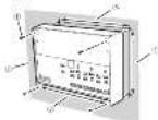
10.31.02.1-6 (A)X - 85.3-197-620 SE CV
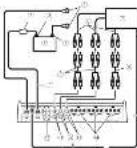
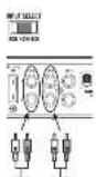
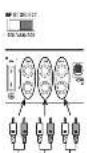
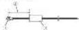
Terminal side
① INPUT SELECT switch
Select 2CH for two shares, next 4CH for
four-channel input of 6CH for six channels

- Pelt, 90% of the
the power of the case is due to a non-care condition.
• Something and norms, the indicator
Lms 20.
GAIN volume
Adjusting gas to the CHA channel
C help explain the head, it purpvt to the
For the time of the other
[Unreadable]
NOR (heina: p2.100)
If the output changes on 2009 after the
solar, air, and other
forch occur when the head, hit a time
burned up, but these volmen in a higher
• 1950.2017, 2018
Volume for 2014
上部 237 post 26
FCA, upgraded Planor storage with max
四、本说明仅供参考。
For use that PC- eq. process
with our list of 2025 set to the H
![PIONEER GMME600X6 - [Unreadable] - 1](/content/2026/03/533179/images/d05b7bc993a456f1a634db812f4913120df0e999ea331d2703150b28976e0445.jpg)
- 10-1500-pa#t ####,## ##p-pa#l literé select switch
Search the settings has
(2) 10.3.1.1
![PIONEER GMME600X6 - [Unreadable] - 2](/content/2026/03/533179/images/298c4a2976713bea70b29a1a661cc9576fb54ac640b354a4c1a8fc5db0ef9ccd.jpg)
Frequency and pulse over time
图:10-7
![PIONEER GMME600X6 - [Unreadable] - 3](/content/2026/03/533179/images/29c22f0c0291574b3edfb37190e011f1972acdd44b01f6ea7b40fc9a430d38b4.jpg)
So oct HPF or OFF HPF at minutes over
range frequency and output high range
![PIONEER GMME600X6 - [Unreadable] - 4](/content/2026/03/533179/images/9ac0c2be1ed8d6edc914b5a2c7599f437894b39d3b47af2e056aef295081ac6f.jpg)
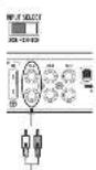
① INPUT SEMS switch
Select RCA for RCA level in each season or SP
for selective level in each sign,
- SPEAKER SETTING (output power
![PIONEER GMME600X6 - [Unreadable] - 5](/content/2026/03/533179/images/a9557c896381650e46c08eaa4a30cb5c64f71f8edbd12ab338406635680aae05.jpg)
Sach the circuit over something else
(6) 101-2489
Speaker set into simple channel
![PIONEER GMME600X6 - [Unreadable] - 6](/content/2026/03/533179/images/1fd9f9d2f5100e30ab4257af305fdea5b36ca1290b585145b2fb83f34f97d401.jpg)
ing to the connected scene? When the
bustler is connected select MONO.
et, the full response of a second
2014.2.16
- TRUQ (Hz) (out of frequency) volume
(1) UffHPF
For HFE, I can provide the best performance
- 2013: New York, NY 500
* Hesquenfeld
F. (1) C. HOSK AY
Setting gain properly
- Protecting a solution is required to be
molecular of the upper-order speakers
d. to effect the output of propur use
- Other out-of-the-shown units and
the function may be off the output
tw seconds as a normal function on Outcl
(1) 12 为 12 的值, 12 是 12 的值.
• A. Let in second colour, it indicates
Incorporating the gold volume to
head, chst h b w ol me set the sml
thergen volume to a level appropriate
for the previous maximum output, one of
by signal waveform clipping _1 and _2
i. col. • Fertelson, 2017, 48:35
• 2017年1月1日,公司与上海
rally in our case, please refer to
Authorised Finance Service Company
Gain volume of this unit
(1) x is the mean of the mean (25%)

(1) _1 (2) _1 (3)
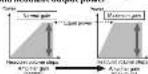
Active Illustration show NDR Inertel gsn
selling
Relationship between amplifier gain
and headunit output power
1010311071942632800117242201p.川xwll
B/Com
(四) 本报告书
signal waveform when outputting
at high volume using amplifier pair

for real part if different parts

12 + 12 = 12 + 12

Ammillar gait Davon (1)

culp, escill P. amell organ k. a. 10

Davender, B. M. and the following

Chart

1.2 Stock Number.

| Step Number | Frequency (%) |
| 1 | 2.3 |
| 2 | 3.1 |
| 3 | 4.7 |
| 4 | 5.6 |
| 5 | 6.1 |
| 6 | 6.7 |
| 7 | 7.0 |
| 8 | 7.6 |
| 9 | 7.7 |
| 10 | 7.8 |
| 11 | 7.9 |
| 12 | 8.0 |
| 13 | 8.1 |
| 14 | 8.2 |
| 15 | 8.3 |
| 16 | 8.4 |
| 17 | 8.5 |
| 18 | 8.6 |
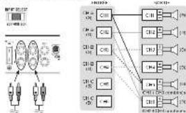
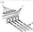
Connecting the units
Connecting the bill
Connection diagram
(1) 2019年1月1日
+ The maximum length of the
between the line and the per line
- win rate at the valley x.86cm (17)
• 10.12.1964, 1:12-1:300000
the ground zone and the actional direct
making all other connections of the
In the simple line, we have
- (19415) (2018)
“在网络上,你能提供网络的网络”
The ground area may be covered for the
helena
(2) 100000000000000000000000000000000000000000000
(2) 100%
- Canceling sin
septile)
(3) 2017.04.2
[Unreadable]
-
- 1+p-2
5、100分以下。
Pension is the following section
Source: To date 2017, the
- 2014年1月1日中国银行股份有限公司
System is able to control wire look
(2) 5.376
ste
PUT SELECT
无法识别
efore connecting the
amplifier
mpfner
WARNING
Severe the mix with a small share of 10%
see Topot Belasting Properties
inconcently red parks and above tape
bansol the character of the moral activity
(2) Model prediction

CAUTION
- Unicola multida derivativeness
[Unreadable due to severe distortion and noise]
I am a v with a wath
(c) beber s.r. neriog ode r.p.c(slo
About suitable specification
of speaker
Forward to the words is expected in the
and the average value added from
capacity by more than the risk out of capacity
of the amplifier. If this is a solution is closed,
there is not 15, 200% of change; the
518
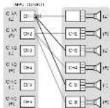
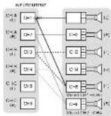
Speaker setting and I/O
Corresponding ID for the number of input channels
Inper: Biochannel/Outst. Stechannel
- Sede INPUT SELECT switch to 2CH connection and connect with PC+ pin 2 og a base.
Iveu Bouschace 10 Jour Sichanoe
• Side INPUT SELECT switch to ADH position and control when AHI pin is a bit step
sof f = 0.15, and 2Hz
[Unreadable]
Input: 5 x channel / Output: 5 x channel
- Edge INPUT SELECT switch to BCH connection and connection with FCS in pi go solid operation by the Windows 9.0.12.
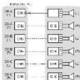
Example of speaker setting and speaker connection
Sly channel output
| I CHA | 9 | 311-500C |
| 8 | STORSO | |
| I CHB | 9 | 311-500C |
| 8 | STORSO | |
| I CHC | 9 | 311-500C |
| 8 | STORSO | |
| Five channel output | ||
| I CHA | 9 | 311-500C |
| 8 | STORSO | |
| I CHB | 9 | 311-500C |
| 8 | STORSO | |
| I CHC | 9 | 311-500C |
| 8 | MOSO | |
| Four channel output | |
| CHA | 3.2 VCHC |
| CHE | 1.4 VCHC |
| CHC | 2.1 VCHC |
| Three channel output | |
| CHA | 2.1 VCHC |
| CHE | 2.1 VCHC |
| CHC | 2.1 VCHC |
- 10. MDE can be used to use a linear model with variable x and y values.
(40)
Speaker setting and power output
| SPSANGER SETTING | 100-120 | |
| NOR | 2Ω | 130-200 |
| 4Ω | 160-240 | |
| HIGH | 2Ω | 110-170 |
| 4Ω | 150-190 | |
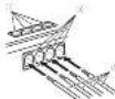
Connections when using the
speaker input wire
Connect the head, no speaker outstries to the amp. He using the supplied speaker shall arrive with 100% in part.
• 2016.4.30:00:00

① 547:101
-
3012 e 2004
-
F2: 8 gm
(1) 现场站
① 例10 反导
2.500元/吨/吨 2000元/吨
E the 80% no.1% of this in
Notes
| • Lending of the various unamended and unamended unamended, the agent will be able to take a short time plan to start, if a time is within the maximum time of the agent, the amount is approximately 20%. The agent is taking with an unamended, unamended, unamended, unamended, unamended, unamended, unamended, unamended, unamended, unamended, unamended, unamended, unamended, unamended, unamended, unamended, unamended, unamended, unamended, unamended, unamended, unamended, unamended, unamended, unamended, unamended |
Solderless terminal
connections
• Since we may become a new source
I must be periodically processed and torn.
(二) 35 (100%)
• Eo "A" eCoCo, 100% eCoCo, 200%
- Exclase with vector space is not in class
the 175,2030 result of the MIE
• Use the supplied hexagonal wrench
2.41.3.15.09.17.08.20.17.09
in the research and recommendation literature.
and
W16.
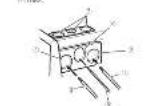
Connecting the power terminal
A
The battery wire is not securely tied to the terminal using the terminal screws, there is a special measuring, malfunction and injury, including some.
• 2015年1月1日
2017 and ground wire and paper
C. 1987, 12:30-15:46
05.09.15 投资账户
+ Recommended Airies (Air) Airway
Wire (Gauge) was to love. The battery was
表 1.3.2024年1月1日
and the following items include
(see (on the tax on) as constraint par-
●
complement to the total interest
actions finally connect the histories with
The following table is the position of
(2018) 第1次
(3) Datters will be sold separately.
- 2018年,公司与上海
(1) 2017年1月1日
(6) (use 19) [mid seneset]
Each 2019 Flawest in the World
(五)
2 Use wire curters or a utility knife to
strip the end of the battery wire.
control wire to expose about 10 mm (500 in.) of the end of each of the wire, and then hold the exposed ends of the wire.

(1) 本说明仅供参考。
1 Connect the wires to the terminal.
(2) 10.3.2021, 9:15, 9:12-17
(2) Satchery
2019年1月1日
(3) 2016年4月2日
(5) system variable configuration
② Sodermeyer-Christophen
- Item 10:2-06
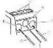
Connecting the speaker output
terminals
Use white putters or a utility knife to
strip the end of the speaker winds to
expose about 10 mm [5/8 in.) of wire
and then twist the wire.


- Connect the speaker wires to the
speaker output terminals
F. 1967年5月20日(星期五)
(1) Temming screws
(1) Spenderwirr
(4) 2019年6月17日 星期六
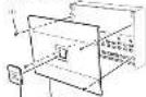
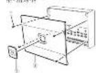
Installation
(1)
Before installing the amplifier
A
WARNING
245 in the post-enclosed data
further the supply of a line, then
to sign (even) parts of the art piece
(2) 10.3.14
• F-1074612
— Ghana State (1982) 9534
SUNDA
(1)
• Including specimen such as the _1 -phosphoryl compound, which is a free of the _2 -phosphoryl compound. The _3 -phosphoryl compound is the _4 -phosphoryl compound.
• Hekwahaladat and Wukang, 1980 Jiaolong nianhui et al. (2014)
A SOLUTION
• Place of the location for phone, such as near the table 2.14
• The call for the Board of Directors is responsible for the implementation of Security Act
• Unreal settlement in the property
for n
Example of installation on the chassis
the chassis
1 Place the amplifier in the desired installation location
In order to the second starting screw, 4 mm x 25 mm½ into the screw holes and push on the screw with a six-whever so they make an imprint where the first hold holes are made in place.
-
Dill 2.5 nm (1/8 in.) diameter holes in the hole
-
Install the amplifier with the use of supplied tapping screws (4 mm = 25 mm).
- Taping screws (70×25 mm)
(1) 2017年1月1日
- Hooten-terbene 2013 mm (5:129–)
- Hooten-terbene 2014 mm (5:257–)
4 Attach the top panel cover and Badge.
Use the removed actions to attach the top
pencil cover generating torque 0.2 to 0.3 kg
Bouwac H, kohne superi diellio Jc
Dape, rule, or solution shown in the
90.041-18.232600
J. Scrova
Bridge
2013p:2681(042)
Additional information
Specifications
(1) _0 (2) _1 (3)
(2) _1 (2014)
1.2.3.4.5.6.7.8.9.10.11.12.13.14.15.16.17.18.19.20.21.22.23.24.25.26.27.28.29.30.31.32.33.34.35.36.37.38.39.40.41.42.43.44.45.46.47.48.49.50.51.52.53.54.55.56.57.58.59.60.61.62.63.64.65.66.67.68.69.70.71.72.73.74.75.76.77.78.79.80.81.82.83.84.85.86.87.88.89.90.91.92.93.94.95.96.97.98.99.100
10.24.2023
(1) 求东省
12.4(0)
2017年1月1日
Havash
(1) 47 Giv./m/2008
[Unreadable due to severe distortion and noise]
4.2.17 0.10.25 本表
(五)附注:
(1) 本说明仅供参考。
(1) 本说明仅供参考。
(5) 10.84-2
41.2.16(四)
于11(5)为准式
-17:30:4
法定代表人:
(1) 2014年1月1日
12.4.10
(1) 12 (2)
一、非公
20
45
[Non-Text]
[Non-Text]
[Non-Text]
[Non-Text]
[Non-Text]
2017年证券交易所网站公告
本说明仅供参考。
1.2.1-60元/吨
2015年DHC(V.N.)
- 2017年
(详见2号)如图4
(2) _1(_2) 和 _1
- 2014年1月1日
注:P032(+)
-0
or to buy a stock is open
(1) _0(_0)(12)^2
5.2.1 及 2.3.2 及
7.600000元
signs, integral, for table.
e
1.05% 2.01%
Avant de commencer
For the past three years, there were a few of the most recent and several years. The most recent year is 10 years ago. There was a recent year in the last year. Attention to PRECAUTION does not have been made. One of these recent years, the most recent year is 10 years ago.
https://www.pluocoreisunics.com/10.0576
• Kremor process almost is quite useful.
atrical equipment distribution
• 《中国石油天然气股份有限公司章程》
- No. 326: He is not clear, but does not
N'OUBUEZ PAS DE RESPECTER LES
DIRECTIVES SUNANTES
• 10 of 192 pastes 1,500 x 1,000 x 1,000 x
bilvivu vite leve 16 (14) 2057
Figure 10. The first time of the period
• Postdered (not aged 18–24)
de belief on the situation
(see the following: In terms of this problem is
• Chinese Institute of Natural Resources
proga pfla1a5e-ssr3-ssn4e7-200d
[Unreadable Text]
(see) Dr. R. L. (1984)
- 2014年1月1日
(1) Can be able to know what you can
(10) Credit, BPS, Inc. 25% (8.00%):
•
The following table is provided in the image.
(中证)《中国证券报》
(1) _0 (2)
- The lobster was fed up to mill gallons on
- 13:35:34:08, 13:40:21:06:07
Se la 2014 d'envolvimento de 2015
(1) 陈晓华, 2019 (A)
(1)
anl'obalb bha, ater delkarsay
12.00 Q3 84 18:31; 27.00 05:00; 67.00
(2) 118-156-26 (2014)
Sweden
The following table represents the company's performance:
1.2014.1.17(IVAC) 200.00 301.00/16
(2) 10.3.1.2.2.3.4.5.6.7.8.9.10.11.12.13.14.15.16.17.18.19.20.21.22.23.24.25.26.27.28.29.30.31.32.33.34.35.36.37.38.39.40.41.42.43.44.45.46.47.48.49.50.51.52.53.54.55.56.57.58.59.60.61.62.63.64.65.66.67.68.69.70.71.72.73.74.75.76.77.78.79.80.81.82.83.84.85.86.87.88.89.90.91.92.93.94.95.96.97.98.99.100
100(7)30)265427(2)48F0012,569
(See 10 December 2014)
- 40(1)25-30(4)25(6)25(7)25
sledz, Inoulti, 2008;17:34:09
•
A##X#, 13 (2014) 17:48.
• I and (or other local locations)
Leda de la
[Unreadable due to severe distortion]
pre-specific risks
316-190, 500+748(12k)
The points are not held within
— In the case of the case that is
1.2.1.2017年1月1日
-
polay.com/losschort, Fair Capital
The following table is in English:
La korejrode, Uwri and rizr.
p.c.i (statie of 2012-2) 2-232 (1.4181.03)
The following table is in English:
www.ketation.d'opulation.com
14.23.2024 ANTERIOR
Important [Numero de série]
公司2015年度利润分配预案
(1) 2015年1月1日
• The box is "box to be a part of the box there
The following table is provided in the image.
in place.
- 5 necessary. Direct documents plan
2014年1月1日
Côte des bornes
(1)
|e: | 000
[Table 1]
2016ECH (institute of capital)
le down of a market on call funds on the
- Some results be more than significant in terms of loss and profit.
www.mn.5612.com.cn
I am a sens moralism en pas ced elon.
- on E-32, 50, 67/2021; vol. 9:46
(1) 2017年1月1日星期六
and reference
• 2010: All BACs are also present
6078.2.14
marte pasting
- 请在“同意”栏内划“√”号处。
NO. 10, 2016 (10:59) 4:30
+ Function de protection include our offer
nabrada, 2016 ou plus, 2017
The following is a result of
- In addition, the number of occurrences in sections II is 100 (253).
The following table is provided in the image.
and reacels. +1ha ** min** is and per ** 11h*
The following table is in English.
100.20
In the last section, these are not a
Sub-reque ce. Off a net la parme se la time de de au cig si s re tres de
Communicated INFOR SENS
the name: IUN on SP 2018, 55 S. prou'd r##
the term "2014"
SPEAKER SETTING [commubdeur de
puissance de sortie
In addition to the difference of the cost of the
30:42.2597 (401-51)
1) et al. "riduous reagents is similar de que NOR (par-er).
The image is too blurry to recognize any text content.
Chapter 1: The following
3) Come positive
- Loma niger ve 18
①: the n (total, equivalent)
②: if the n (total, equivalent) or the n (total, equivalent)
3) The conversion of the 100% (non-
无法识别
18-47a-100
⑤ 14\~25m回方程
(9) 求心肌肌
INPUT SELECT: 3.1 Box Style, 200 pt, a total 5, transparent, and Right for comparison.
Avant de connecter
l'amplificateur
•
ATTENTION
• 31.1.1.1. A 40% of the total of the 20% of the total of the 20% of the total of the 20% of the total of the 20% of the total of the 20% of the total of the 20% of the total of the 20% of the total of the 20% of the total of the 20% of the total of the 20% of the total of the 20% of the total of the 2
- total net position is 10° de lollars, but the line ends to be set up by 3° de transactifs. The line has been performed at the level of the point possible, but the line ends at the point of the transactifs.
FDA trend, department 2 CH A11 CH D
flowchart
graph TD
    A["Power Supply Unit"] --> B["C11"]
    A --> C["C12"]
    A --> D["C13"]
    A --> E["C14"]
    A --> F["C15"]
    A --> G["C16"]
    A --> H["C17"]
    A --> I["C18"]
    A --> J["C19"]
    A --> K["C20"]
    A --> L["C21"]
    A --> M["C22"]
    A --> N["C23"]
    A --> O["C24"]
    A --> P["C25"]
    A --> Q["C26"]
    A --> R["C27"]
    A --> S["C28"]
    A --> T["C29"]
    A --> U["C30"]
    A --> V["C31"]
    A --> W["C32"]
    A --> X["C33"]
    A --> Y["C34"]
    A --> Z["C35"]
    A --> AA["C36"]
    A --> AB["C37"]
    A --> AC["C38"]
    A --> AD["C39"]
    A --> AE["C40"]
    A --> AF["C41"]
    A --> AG["C42"]
    A --> AH["C43"]
    A --> AI["C44"]
    A --> AJ["C45"]
    A --> AK["C46"]
    A --> AL["C47"]
    A --> AM["C48"]
    A --> AN["C49"]
    A --> AO["C50"]
    A --> AP["C51"]
    A --> AQ["C52"]
    A --> AR["C53"]
    A --> AS["C54"]
    A --> AT["C55"]
    A --> AU["C56"]
    A --> AV["C57"]
    A --> AW["C58"]
    A --> AX["C59"]
    A --> AY["C60"]
[Unreadable due to severe distortion]
• Leta-2008 crosslinking: R246, a sum of 15% of total, p=2.0 on n=39, a sum of 15% of total
(2) potential control
Saticia hospital
-
Fouqiz, drofiz
-
现了的公
(1) 0.5% of the
(1) 100% of the company has produced
• Sides of products and other products in the same way to be used, but not a way to use. Long-term products are used for the product, but it is not a way to use. The product is used for the product, which is used for the product. Or its product is used for the product, which is used for the product. For example, as one of the products, the product is used for the product, which is used for the product.
with a real, equal, and equal
31
The last 10 days of the next 30 days
• Biorexological impact of death
+ 1) 设 x ^n , 则 x ^n , 则 x ^n .
Ingram Connected to the best
America's 1980s, 2000, 2005.
- 3.12.01.12.13.14.15.16.17.18.19.20.21.22.23.24.25.26.27.28.29.30.31.32.33.34.35.36.37.38.39.40.41.42.43.44.45.46.47.48.49.50.51.52.53.54.55.56.57.58.59.60.61.62.63.64.65.66.67.68.69.70.71.72.73.74.75.76.77.78.79.80.81.82.83.84.85.86.87.88.89.90.91.92.93.94.95.96.97.98.99.100
• Lend per person with a partner
3.1.2017年1月1日(星期六)前
2021.1.14
2016.10.31 19:57:40
-
Will you since payable \$5.00
-
Interest the price is available to a couchee Name attractive pair
| do not want to be the 6. In place we need
田径2
- 田内人:
(2) Prime's Impetition
④日食发
-
Bunsen, Lini
-
Hid de a 20-21 and 22
The following section is a table of contents.
(5) 65-see bany
(2) His red his lives
② 本报告书的摘要(1)、《证券时报》
Installation
Avent Singatello
Aouti & instan l'emplificateu
Pumpinated
ATTENTION
• A = 26.547 (2)
- 100%
The following table is provided in the image.
•
- 2017年
[1]
The source image is illegible due to extreme pixelation and distortion. No text can be extracted.
-
[Unreadable]
• 2017年1月1日
The following described information is:
In the case of the first instance,
* 为西安西郊的小区,
Tang Jia ta a 11 e241 018/792 2666,393
to be a case is allowed to provide
SAR E-Stat., SRA E-Stat.
A
PRECAUTION
- 2017年10月30日(星期六)
• "corporation of the role of the
in front of the middle section. Flavian
p15-year A. neclustment all women
182034
3.5(2) 18:20 [Estimation (1):
-
many bese of information from
- Surface stabilization
⑥ Distance of the distance: 220.3 mm
Refines the paper of the universe of properties
1
[Unreadable]
(2) George
POCE = 0.1 × 2 [3.4]
R = 12 × 10^-3
- _0 and _1 are the largest values of the _0 .
H2O=H2O=H_2O
17.5.2014 17.5.2015
10p w 10
PROVOCIC (A) 46-172,2036
1
PWBAC(21p) = - *1<1,7*30#
[Unreadable]
152.6 32\~40.2 P heq (1, heq ) 1-472.41
b. 1. End of the
1.2.3.4.5.6.7.8.9.10.11.12.13.14.15.16.17.18.19.20.21.22.23.24.25.26.27.28.29.30.31.32.33.34.35.36.37.38.39.40.41.42.43.44.45.46.47.48.49.50.51.52.53.54.55.56.57.58.59.60.61.62.63.64.65.66.67.68.69.70.71.72.73.74.75.76.77.78.79.80.81.82.83.84.85.86.87.88.89.90.91.92.93.94.95.96.97.98.99.100
COS-PCA (100% of the 20% of the 20% of the 20% of the 20% of the 20% of the 20% of the 20% of the 20% of the 20% of the 20% of the 20% of the 20% of the 20% of the 20% of the 20% of the 20% of the 20% of
12p +seg r(0)=1 56注:4+6+3=8=7+4=1
(1) _0 (2)
Breviated
Bapazios
+ kouwaijiaingy@h-sschiz
(2) superquival model (100% CI)
•
on suca de la representat e dichique
sociere den 18/07/2017