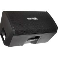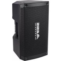
Strike Amp 8 - Musical instrument ALESIS - Free user manual and instructions
Find the device manual for free Strike Amp 8 ALESIS in PDF.



User questions about Strike Amp 8 ALESIS
0 question about this device. Answer the ones you know or ask your own.
Ask a new question about this device
Download the instructions for your Musical instrument in PDF format for free! Find your manual Strike Amp 8 - ALESIS and take your electronic device back in hand. On this page are published all the documents necessary for the use of your device. Strike Amp 8 by ALESIS.
USER MANUAL Strike Amp 8 ALESIS
User Guide (English)
Introduction
Thank you for purchasing the Strike Amp 12 or Strike Amp 8. At Alesis Drums, we know how serious music is to you. That's why we design our equipment with only one thing in mind—to make your performance the best it can be.
Box Contents
Strike Amp 12 or Strike Amp 8
Power Cable
User Guide
Safety & Warranty Manual
Support
For the latest information about this product (documentation, technical specifications, system requirements, compatibility information, etc.) and product registration, visit alesis.com.
For additional product support, visit alesis.com/support.
Setup
Items not listed under Introduction > Box Contents are sold separately.
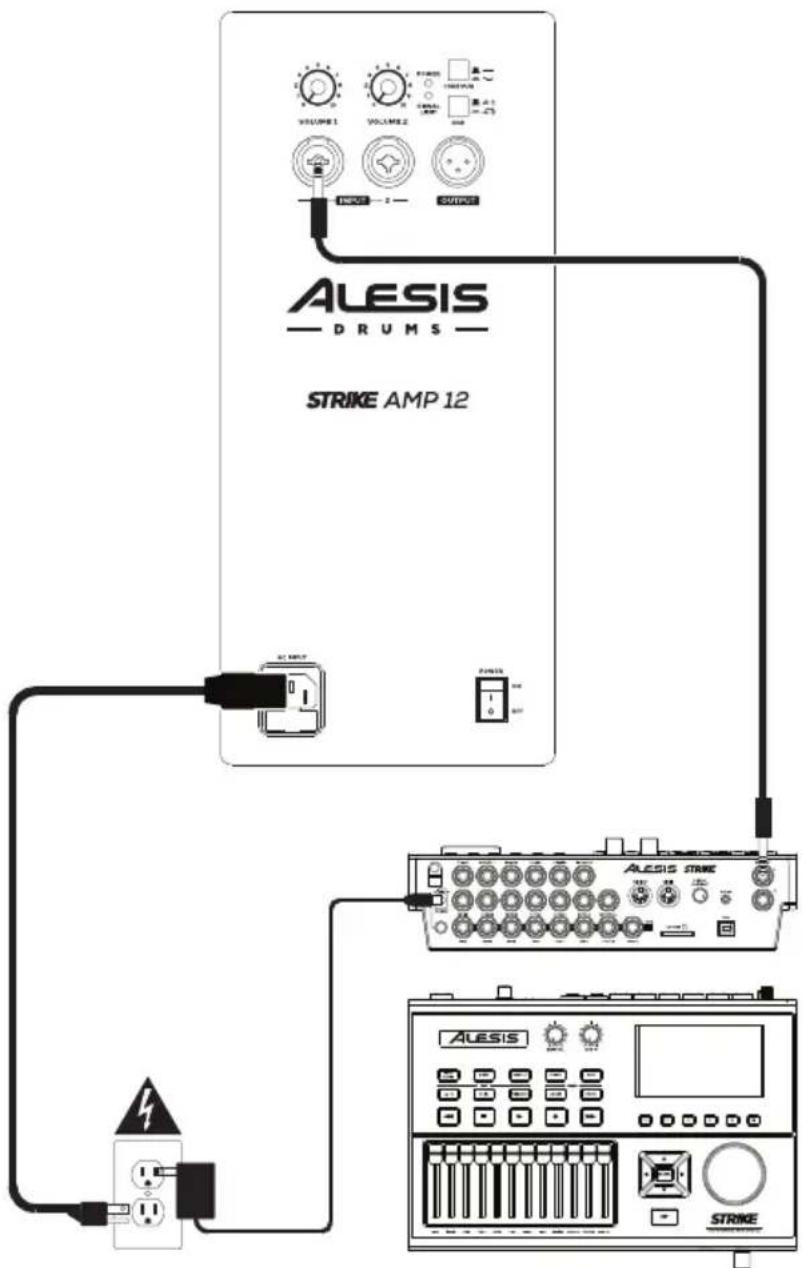
Example A: One Strike Amp (Mono)
Connect the Left (Mono) output of your drum module to the input on a Strike Amp.
flowchart
graph TD
    A["Input Signal"] --> B["Resistor"]
    B --> C["AMP 12"]
    C --> D["ALESIS Trigger"]
    C --> E["ALESIS"]
    C --> F["Strike"]
    style A fill:#f9f,stroke:#333
    style D fill:#ccf,stroke:#333
    style E fill:#ccf,stroke:#333
    style F fill:#ccf,stroke:#333
Power Outlet Drum Module
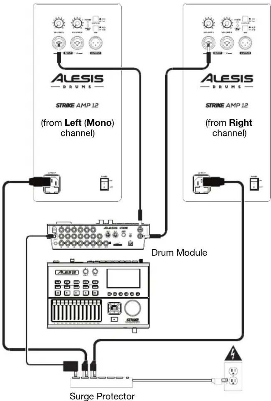
Example B: Two Strike Amps (Stereo)
Connect the Right and Left (Mono) outputs of your drum module to the inputs of your Strike Amps.
flowchart
graph TD
    A["ALESIS DRUM"] --> B["STRIKE AMP 12 (from Left (Mono) channel)"]
    C["ALESIS DRUM"] --> D["STRIKE AMP 12 (from Right channel)"]
    B --> E["Drum Module"]
    D --> E
    E --> F["Surge Protector"]
    F --> G["Ground"]
    style A fill:#f9f,stroke:#333
    style C fill:#f9f,stroke:#333
    style E fill:#ccf,stroke:#333
    style F fill:#cfc,stroke:#333
Example C: Two Strike Amps (Mono)
Connect the Left (Mono) output of your drum module to the input of one Strike Amp, and then connect the output of that Strike Amp to the input of another.
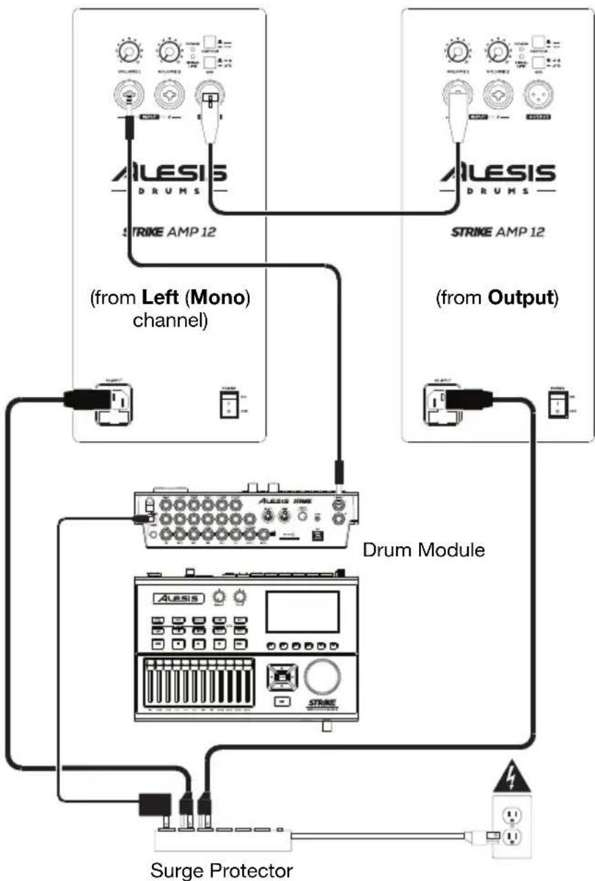
flowchart
graph TD
    A["ALESIS DRUMS"] -->|STRIKE AMP 12| B["(from Left (Mono) channel)"]
    C["ALESIS DRUMS"] -->|STRIKE AMP 12| D["(from Output)"]
    B --> E["Drum Module"]
    D --> E
    E --> F["Surge Protector"]
    F --> G["Output"]
Strike Amp 12 Features
Rear Panel
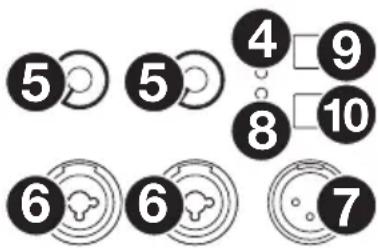
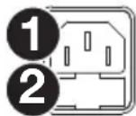
- AC Input: Use the included power cable to connect this input to a power outlet. Make sure the Power Switch is set to off when connecting or disconnecting the cable.
- Fuse: If the unit's fuse is broken, lift this tab to replace the fuse. Replace it with a fuse with an appropriate rating (printed under the unit's power cable input). Using a fuse with an incorrect rating can damage the unit and/or fuse.
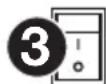
- Power Switch: Use this switch to power the loudspeaker on or off. Make sure Volume knob is set to its minimum (counterclockwise) position before turning it on.
- Power LED: This LED lights up when the loudspeaker is on.
- Volume: Turn each knob to adjust the volume of each input.
- Input: Use a standard XLR cable or 1/4" (6.35 mm) TRS cable (not included) to connect your audio source to this input.
- Output: Use a standard XLR cable (not included) to connect this output to the input of another loudspeaker (i.e., another Strike Amp).
- Signal Limit LED: This LED lights up green when an audio signal is sent to the loudspeaker—it flashes at lower levels and lights solidly at higher levels. The LED lights up red when output limit/protection is active—if the LED is lit red continuously, reduce the volume of your audio source.
- Contour: Engage (depress) this button to emphasize low and high frequencies by +3 dB. Disengage (raise) the switch for a flatter response for live performance or for maximum output.
- Ground Switch: Engage (depress) this switch to reduce hum or noise.
text_image
5 5 4 9 8 10 6 6 7the

STRIKE AMP 12
Strike Amp 8 Features
Rear Panel
- AC Input: Use the included power cable to connect this input to a power outlet. Make sure the Power Switch is set to off when connecting or discon necting the cable.
- Fuse: If the unit's fuse is broken, lift this tab to replace the fuse. Replace it with a fuse with an appropriate rating (printed under the unit's power cable input). Using a fuse with an incorrect rating can damage the unit and/or fuse.
- Power Switch: Use this switch to power the loudspeaker on or off. Make sure the Volume knob is set to its minimum (counterclockwise) position before turning it on.
- Power LED: This LED lights up when the loudspeaker is on.
- Volume: Turn each knob to adjust the volume of each input.
- Input: Use a standard XLR cable or 1/4" (6.35 mm) TRS cable (not included) to connect your audio source to this input.
- Output: Use a standard XLR cable (not included) to connect this output to the input of another loudspeaker (i.e., another Strike Amp).
- Signal Limit LED: This LED lights up green when an audio signal is sent to the loudspeaker—it flashes at lower levels and lights solidly at higher levels. The LED lights up red when output limit/protection is active—if the LED is lit red continuously, reduce the volume of your audio source.
- Contour: Engage (depress) this button to emphasize low and high frequencies by +3 dB. Disengage (raise) the switch for a flatter response for live performance or for maximum output.
- Ground Switch: Engage (depress) this switch to reduce hum or noise.
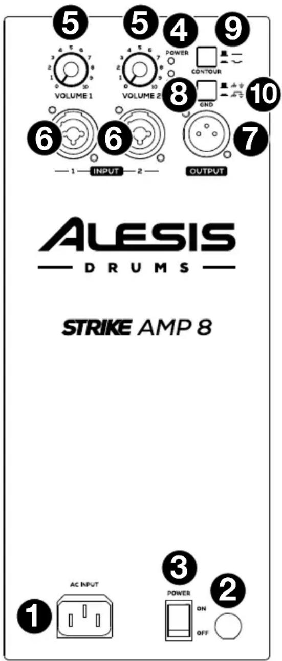
text_image
5 4 5 4 9 VOLUME 1 POWER CONTOUR 6 VOLUME 2 8 GND 1 INPUT 2 OUTPUT 7 ALESIS — DRUMS — STRIKE AMP 8 1 AC INPUT 3 POWER ON OFF 2Assistance technique
flowchart
graph TD
    A["Steckdose"] --> B["Drum-Modul"]
    B --> C["ALESIS DRUM"]
    C --> D["STRIKE AMP 12"]
    D --> E["Control Signals: VOLUME 1, VOLUME 2, VOLUME 3, VOLUME 4, VOLUME 5, VOLUME 6, VOLUME 7, VOLUME 8, VOLUME 9, VOLUME 10"]
    C --> F["Control Signals: VOLUME 10, VOLUME 11, VOLUME 12, VOLUME 13, VOLUME 14, VOLUME 15, VOLUME 16, VOLUME 17, VOLUME 18, VOLUME 19"]
    C --> G["Control Signals: VOLUME 18, VOLUME 20, VOLUME 22, VOLUME 23, VOLUME 24, VOLUME 25"]
Strike Amp 12 Technical Specifications
| Output Power | 2000 W (peak, 1300 LF + 700 HF)1000 W (continuous RMS, 650 LF + 350 HF) | |
| Drivers | Low-Frequency | 12.0" (305 mm) low-frequency driver, 3.0" (76 mm)high-temperature voice coil |
| High-Frequency | 1.4" (35 mm) voice coil, neodymium-magnethigh-frequency driver with precision waveguide | |
| Crossover Frequency | 2.0 KHz | |
| Maximum SPL | 131 dB (peak), 128 dB (continuous) (dB-SPL @ 1 m) | |
| Frequency Response | 53 Hz - 20 kHz ( ± 3 dB) | |
| Frequency Range | 46 Hz - 22 kHz (-10 dB) | |
| Horn Coverage | 90° horizontal x 60° vertical (nominal) | |
| Equalization | Contour switch with low- and high-frequency +3 dB boost | |
| Connectors | (2) XLR/TRS 1/4" (6.35 mm) combo inputs(1) XLR link output(1) IEC power cable input | |
| Controls | Power switch, (2) volume control knobs (1 per input), EQ contour switch,ground-lift switch | |
| Indicators | (2) power LEDs (1 front-panel, 1 rear-panel), clip limiter LED | |
| Protection | Electronic clip, thermal & transducer overdrive | |
| Power | Connection | IEC |
| Input | 100 V~, 110V~; 220–240 V~; 50/60 Hz (switchable) | |
| Fuse | 100–120V T10AL AC250V220–240V T5AL AC250V | |
| Consumption | 800 W | |
| Enclosure | Trapezoidal, injection-molded polypropylene enclosure with perforatedsteel grille | |
| Dimensions (height x width x depth) | 23.8" x 13.9" x 13.8"605 x 354 x 350 mm | |
| Weight | 35.9 lb.16.3 kg | |
Specifications are subject to change without notice.
Strike Amp 8 Technical Specifications
| Output Power | 2000 W (peak, 1300 LF + 700 HF)1000 W (continuous RMS, 650 LF + 350 HF) | |
| Drivers | Low-Frequency | 8.0" (203 mm) driver, 2.5" (65 mm) high-temperature voice coil |
| High-Frequency | 1.4" (35 mm) neodymium driver with precision waveguide | |
| Crossover Frequency | 2.5 KHz | |
| Maximum SPL | 129 dB (peak), 126 dB (continuous) (dB-SPL @ 1 m) | |
| Frequency Response | 62 Hz - 20 kHz (±3 dB) | |
| Frequency Range | 52 Hz - 22 kHz (-10 dB) | |
| Horn Coverage | 90° horizontal x 60° vertical (nominal) | |
| Equalization | Contour switch with low- and high-frequency +3 dB boost | |
| Connectors | (2) XLR/TRS 1/4" (6.35 mm) combo inputs(1) XLR link output(1) IEC power cable input | |
| Controls | Power switch, (2) volume control knobs (1 per input), EQ contour switch, ground-lift switch | |
| Indicators | Power LED (rear panel), clip limiter LED | |
| Protection | Electronic clip, thermal & transducer overdrive | |
| Power | Connection | IEC |
| Input | 100 V~, 110Voltage, 220-240 V~; 50/60 Hz (switchable) | |
| Fuse | 100-120V T10AL AC250V220-240V T5AL AC250V | |
| Consumption | 800 W | |
| Enclosure | Trapezoidal, injection-molded polypropylene enclosure with perforated steel grille | |
| Mounting | Standard 36 mm pole socket | |
| Dimensions (height x width x depth) | 17.1" x 10.1" x 9.6"434 x 256 x 245 mm | |
| Weight | 20.2 lb.9.2 kg | |
Trademarks & Licenses
Alesis is a trademark of inMusic Brands, Inc., registered in the U.S. and other countries.
All other product or company names are trademarks or registered trademarks of their respective owners.