
HCM574E - Surveillance Camera HONEYWELL - Free user manual and instructions
Find the device manual for free HCM574E HONEYWELL in PDF.
| Product type | Monochrome surveillance camera |
| Brand and model | Honeywell HCM574E |
| Dimensions (W x H x D) | 58 mm x 66 mm x 131 mm |
| Weight | 680 g |
| Power supply | 12 VDC/24 VAC ±15% |
| Maximum power consumption | 3.2 W |
| Image sensor | 1/3" CCD Interline |
| Resolution | 580 TV lines |
| Minimum sensitivity | 0.15 lux @ F1.2 (50 IRE) |
| Lens mount | C/CS adjustable |
| Compatible lens types | Fixed, manual, video or DC auto iris |
| Automatic electronic shutter (AES) | Yes, from 1/50 to 1/100000 s |
| Backlight compensation (BLC) | Yes, switchable on/off |
| Automatic gain control (AGC) | Low (30 dB) or high (36 dB), selectable |
| Synchronization | Internal (INT) or line lock (LL) |
| Video output | 1.0 Vp-p, 75 ohms, unbalanced BNC |
| Signal-to-noise ratio | 50 dB |
| Operating temperature | -10°C to +50°C |
| Mounting | 1/4-20 screw (top and bottom) |
| Warranty | 2 years from date of manufacture |
| Maintenance | Entrust to qualified personnel; technical support at +1.800.796.CCTV |
| Safety | Do not open (risk of electric shock); installation by qualified personnel; Class 2 power supply |
| Spare parts and repairability | Contact Honeywell customer service for parts and repairs |
Frequently Asked Questions - HCM574E HONEYWELL
User questions about HCM574E HONEYWELL
0 question about this device. Answer the ones you know or ask your own.
Ask a new question about this device
Download the instructions for your Surveillance Camera in PDF format for free! Find your manual HCM574E - HONEYWELL and take your electronic device back in hand. On this page are published all the documents necessary for the use of your device. HCM574E by HONEYWELL.
USER MANUAL HCM574E HONEYWELL
E-Series Cameras NTSC/EIA
HCC334E HCM384E
HCC484E HCM574E
Installation Guide
Revisions
Issue Date Revisions
1.00 09/04 New document, based on HCMU00919
Rev A (HCC334E/HCC484E User
Manual) and HCMU000920 Rev A
(HCM384E/HCM574E User Manual).
1.01 05/05 Translated to French and Spanish.
Added figure 2.
Explanation of Graphical Symbols
This symbol indicates the presence of uninsulated “dangerous voltage” within the product’s enclosure that may be of sufficient magnitude to constitute a risk of electric shock to persons.

This symbol indicates the presence of important operating and maintenance (servicing) instruction in the literature accompanying the product.
natural_image
Warning symbol of a lightning bolt inside a triangle (no text or numbers)CAUTION
RISK OF ELECTRIC SHOCK DO NOT OPEN

CAUTION: TO REDUCE THE RISK OF ELECTRIC SHOCK, DO NOT REMOVE COVER (OR BACK). NO USER-SERVICEABLE PARTS INSIDE. REFER SERVICING TO QUALIFIED SERVICE PERSONNEL.
Warnings
Installation and servicing should be performed only by qualified and experienced personnel.
Low voltage cameras must be powered from a UL Listed Class 2 power supply.
For outdoor use, an appropriate protective housing conforming to IP65.

To prevent fire or shock hazard, do not expose this camera to rain or moisture.
Safeguards
This camera range is designed for use in general-purpose CCTV applications and no other purpose.
Only operate your camera between the temperature of -10^ to +50^ ( 14^ to 122^ ).
Do not operate your camera outside its specified power supply range.
Camera must only be used in clean, dry, dust-free environments unless housed in suitable protective housings to IP65 or better.
Electromagnetic Compatibility (EMC)

This is a Class B product. In a domestic environment this product may cause radio interference, in which case the user may be required to take adequate measures.
INTENDED PURPOSE:
SECURITY AND SURVEILLANCE CCTV APPLICATIONS.
The product must be installed and maintained in accordance with good installation practice to enable the product to function as intended and to prevent problems. Refer to Honeywell Video Systems for installation guidance.
Manufacturer's Declaration of Conformance
The manufacturer declares that the equipment supplied with this guide is compliant with the essential protection requirements of the EMC directive 89/336/EEC and the Low Voltage Directive LVD 73/23 EEC, conforming to the requirements of standards EN 55022 for emissions, EN 50130-4 for immunity, and EN 60065 for Electrical Equipment safety.
Contents
Introduction 1
Features 1
Package Contents 2
Camera Settings....2
Camera Back 2
AI/AES Mode Selector 3
Auto Iris Lens Type Selector (Video Drive or Direct DC Drive) . . 3
Backlight Compensation 3
AGC Low / AGC High 3
Synchronization Selection (LL/INT) 4
Line Lock Phase Adjustment Potentiometer 4
DD Lens Level Adjustment Potentiometer 4
Power LED 5
Composite Video Output BNC Connector 5
Power Supply....5
Lens Selection 5
Back Focus Adjustment 6
Lens Installation 7
Installing Fixed Iris Lenses 7
Installing Manual Iris Lenses 7
Installing Auto Iris Lenses 7
Installing Direct (or D.C.) Drive Lenses. 7
Installing Video Drive Lenses 8
Complete the Installation 9
Mounting the Camera 9
Connecting the Camera 10
Troubleshooting 11
Service and Support 12
Service and Support 12
Limited Warranty 12
Specifications 13
General Specifications 13
Functional Specifications 14
Video Specifications 14
Introduction
Honeywell's E-Series (color and monochrome) cameras are ideally suited for use in day-to-day surveillance applications. The E-Series cameras are designed for exceptional value and performance for everyday use. Their off-the-shelf feature set is designed for high picture quality in standard applications and they require little to no adjustment after installation.
Note All the information in this guide pertains to both color and monochrome models, unless otherwise stated.
Features
| Features | HCC334E | HCC484E | HCM384E | HCM574E |
| Mono | √ | √ | ||
| Color | √ | √ | ||
| Image Sensor: | 1/3" 1/3" 1/3" 1/3" | |||
| Resolution (TV lines) | 330 480 380 580 | |||
| Sensitivity (lux @ F1.2) | 0.75 0.70 0.20 0.15 | |||
| Backlight Compensation (BLC) automatic on/off: | √ | √ | √ | √ |
| Auto Electronic Shutter (AES): | √ | √ | √ | √ |
| Lens Mount C/CS adjustable: | √ | √ | √ | √ |
| Lens Support DD or Video Drive Auto Iris: | √ | √ | √ | √ |
| Line Lock with phase adjust: | √ | √ | √ | √ |
| Supply: Low Voltage (12 VDC/24 VAC) | √ | √ | √ | √ |
Package Contents
Check that the items received match those listed on the order form and packing slip. The E-Series camera packing box should include, in addition to this User Guide:
• One E - Series camera
- One dust cover
- H e x s c r e w d r i v e r
If any parts are missing or damaged, contact the dealer you purchased the camera from or call Honeywell Customer Service.
Camera Settings
Camera Back
Figure 1 Rear View
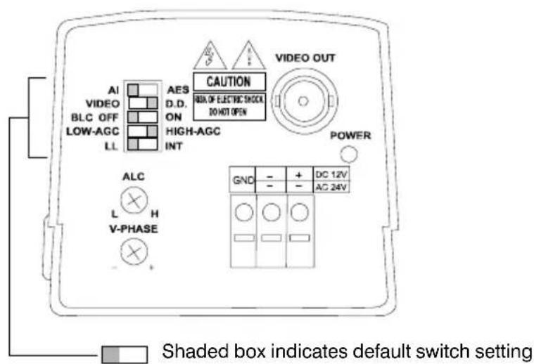
AI/AES Mode Selector
The Auto Electronic Shutter (AES) feature compensates for excessive light levels by automatically adjusting the shutter speed of the camera. Select AES for manual iris lenses. The default setting is AI.
Auto Iris Lens Type Selector (Video Drive or Direct DC Drive)
Automatic iris lenses (Direct Drive (DC) or Video Drive types) are connected to the camera via a 4-pin square socket located at the side of the camera. Select the AI switch on the rear of the camera for all automatic iris lenses. Then set the Auto Iris Lens Type Selector to VIDEO (Video drive) or DD (Direct DC drive), depending on your particular lens. The default setting is DD.
Backlight Compensation
If a strong background light such as a window exists in a scene, the camera tries to compensate by reducing the overall exposure. This means that areas surrounding the window become too dark. Set the backlight compensation (BLC) to ON to eliminate the effect of an area of strong background lighting in a scene. The default setting is BLC OFF.
BLC will only function with a manual iris lens when the Electronic Iris feature is switched on. For Direct Drive and Video drive lenses, BLC will function even though the Electronic Iris feature is switched off.
AGC Low / AGC High
The Automatic Gain Control feature can improve picture quality when the level of scene illumination is low. For most applications, select AGC HIGH (the default setting).
Synchronization Selection (LL/INT)
This switch is used to select the synchronisation mode of the camera. When the camera is connected to an AC supply (either Mains or 24V Low Voltage), the Line-lock (LL) mode can be used to lock the camera's frame rate to the mains frequency so that each camera in the system is triggered at the same point on the supply's AC-cycle. See also Line Lock Phase Adjustment Potentiometer. The default setting is LL.
WARNING! The LL/INT switch must be set to INT when operating from 12 VDC.
Line Lock Phase Adjustment Potentiometer
When the camera is in Line-lock mode it is possible to adjust the point on the AC cycle at which the camera triggers. This facility is provided so that cameras that are connected to different mains phases may still be synchronized.
The V-Phase adjustment potentiometer allows the line lock phase trigger point to be adjusted by: 1:120°. Rotating the potentiometer clockwise advances the trigger point and turning it counterclockwise retards the trigger point. The factory default setting is the zero crossing point. If all cameras in a system are on the same mains phase then no line lock phase adjustment should be made. See also Synchronization Selection (LL/INT).
DD Lens Level Adjustment Potentiometer
The Direct Drive lens level is controlled by this potentiometer. The video output signal is converted into DC voltage by circuitry within the camera. The potentiometer sets a reference voltage against which this derived DC voltage is compared. If the DC voltage is less than the reference level, the lens iris opening is increased. If the DC voltage is greater than the reference level, the lens iris opening is decreased. This control loop attempts to continually match the DC voltage derived from the video signal to the reference voltage set by the potentiometer. This feature allows the installer to set the required video output amplitude (for example, 1 Vp-p) that the lens should strive to maintain.
Power LED
In normal operation, the LED on the rear panel of the camera is illuminated when power is connected to the camera.
Composite Video Output BNC Connector
To obtain a 1.0 Vp-p composite video signal, connect a video coaxial cable terminated with a 75 Ohm BNC connector to the BNC socket marked VIDEO OUT.
Power Supply
The voltage required to operate the camera is clearly marked on the rear panel of the camera. Connections are indicated above the terminals on the rear panel of the camera.
Lens Selection
Suitable lens types are C- and CS-mount in fixed iris, manual iris, video auto iris, or direct drive auto iris versions. Cameras are factory set for CS-mount lenses.
If using a C-mount lens, rotate the back focus adjustment mechanism fully clockwise (when viewed from the front of the camera) before fitting the lens. See “Back Focus Adjustment” on page 6.
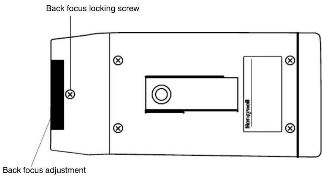
Back Focus Adjustment
The back focus adjustment is accessible at the front end of the camera housing to adjust the back focal length or picture focus.
The range of adjustment allows both C- and CS- mount lenses to be used without the need for a spacer ring.
To use the back focus mechanism:
- Unlock the back focus mechanism by loosening the locking screw (see Figure 2).
Figure 2 Back Focus Adjustment Lock
-
Rotate the back focus adjustment ring as required. When viewed from the front of the camera, clockwise adjustment moves the CCD sensor away from the back of the lens; counter clockwise adjustment moves the CCD sensor towards the back of the lens.
-
Tighten the back focus locking screw.
Lens Installation
Installing Fixed Iris Lenses
To install a fixed iris lens:
- Turn the back focus adjustment ring fully clockwise (when viewed from the front). See “Back Focus Adjustment” on page 6.
- Fit the lens to the camera and rotate clockwise until the lens is fully screwed into the camera.
- If the lens has a focusing ring fitted, set it to infinity ( ) then adjust the back focus. See “Back Focus Adjustment” on page 6.
- Ensure the shutter control is set to Auto Electronic Shutter (AES).
Installing Manual Iris Lenses
To install a manual iris lens:
- Turn the back focus adjustment ring fully clockwise (when viewed from the front).
- Fit the lens to the camera and rotate clockwise until the lens is fully screwed into the camera.
- Ensure the shutter control is set to Auto Electronic Shutter (AES).
- Adjust the back focus using the back focus ring on the front of the camera. See "Back Focus Adjustment" on page 6.
Installing Auto Iris Lenses
Installing Direct (or D.C.) Drive Lenses
To install a Direct or D.C. Drive Lens:
- Turn the back focus adjustment ring fully clockwise (when viewed from the front.)
- Fit the lens to the camera and rotate clockwise until the lens is fully screwed into the camera.
If the lens is equipped with a 4-pin connector, plug the connector into the terminal on the side of the camera.
If the lens is not equipped with the connector, connect it according to Figure 3 below.
Figure 3 Connector Pinouts (Direct Drive or DC Drive)
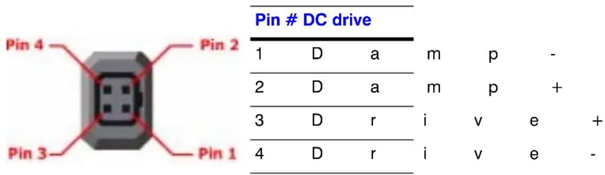

Warning The maximum load for this type of lens must not exceed 25 mA.
- Set the Auto Iris selector (see Figure 1) to AI.
- Set the Auto Iris lens selector to DD for Direct Drive lenses.
- Adjust the back focus using the back focus mounting ring on the front of the camera. See "Back Focus Adjustment" on page 6.
- With typical scene illumination, set the ALC Level adjustment potentiometer (see Figure 1), lens iris for the correct exposure. This can be achieved either visually, or by using an oscilloscope to set the output of the camera to 1 Vp-p.
Installing Video Drive Lenses
To install a video drive lens:
- Turn the back focus adjustment ring fully clockwise (when viewed from the front). See "Back Focus Adjustment" on page 6.
- Fit the lens to the camera and connect it according to Figure 4 below.
Figure 4 Connector Pinouts (Video Drive)
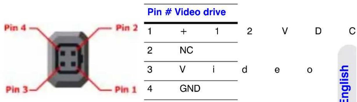

Warning The maximum load for this type of lens must not exceed 25 mA.
- Set the Auto Iris selector (see Figure 1) to AI.
- Set the Auto Iris lens selector switch to VIDEO for video auto iris lenses.
- Adjust the back focus using the back focus mounting ring on the front of the camera. See "Back Focus Adjustment" on page 6.
- With typical scene illumination, set the ALC Level adjustment potentiometer for the correct exposure. This can be done visually. More accurate results will be achieved using a video level meter or oscilloscope to set the output of the camera to 1 Vp-p.
- If the scene lighting conditions are extremely uneven, it may be necessary to adjust the Peak Average potentiometer on the lens. For more information, please refer to the instructions that came with the lens.
Complete the Installation
Mounting the Camera
Mounting points are provided on the top and bottom of the camera and are used to mount the camera on a bracket or tripod. They are designed to accept standard 1/4-20 mounting bolts.
The mounting bracket must be capable of supporting the weight of the camera and its lens. In cases where the lens is substantially heavier than the camera, it is better to use the mounting point on the lens itself.
Note Some installation codes dictate that the mounting bracket must be capable of supporting up to four times the combined weight of the camera and lens.
The mounting bracket is not evaluated by UL.
Connecting the Camera
- Connect the camera to a monitor using compatible coaxial cable.
- Connect the camera to a power supply appropriate for your installation.
- Plug in the power supply and switch on the power to the camera.
- Adjust the lens for optimum picture quality. See "Camera Settings" on page 2.
Troubleshooting
If this happens ... Try this ...
No power / LED not lit • Check the power connections.
- Verify that the power supply is working. (Use a camera that is known to be good.)
No video • Check power connections.
- Check BNC connections. (Use a camera that is known to be good).
- Check the lens. Remove the lens. If video is present, the lens is the source of problem.
Power but picture is black •
D C Check that the Auto Iris lens selector switch is set to DC.
- Increase DC level.
- Check wiring connections.
- Manual Iris. Check that iris is not closed.
Video iris • Verify that Auto Iris lens selector switch is set
to AI. Increase level on lens.
- Check wiring conditions.
- Try lens on another camera or known good lens on camera.
Dark picture • Check lens iris.
- Check coax termination is 75 Ohm.
Picture noise / grainy during daylight operation
Verify lens iris level with AGC function disabled.
Picture too bright
• Manual Iris. Switch AES ON.
• DC Iris. Switch AI ON, adjust ALC.
• Video Iris. Switch AI ON, reduce level on lens.
Picture not sharp (out of focus)
- Adjust focus on lens.
- Adjust back focus.
Picture goes soft (out of focus) in low light
Adjust focus under low light conditions or use a neutral density filter under normal lighting conditions.
Camera roll
When operating 12 VDC, set Line Lock (LL) switch to INT (Internal).
Service and Support
Service and Support
Refer servicing to qualified personnel or contact Honeywell Technical Support at +1.800.796.CCTV for assistance.
Limited Warranty
Honeywell International Inc. ("Seller"), warrants this camera to be in conformance with its own plans and specifications and to be free from defects in materials and workmanship under normal use and service for a period of up to two (2) years from the date of manufacture. Seller's obligation shall be limited to repairing or replacing, at its option, free of charge for materials or labor, any product which is proved not in compliance with Seller's specifications or proves defective in materials or workmanship under normal use and service. Seller shall have no obligation under this Limited Warranty or otherwise if the product is altered or improperly repaired or serviced by anyone other than Honeywell factory service. For warranty service, contact your local Honeywell representative or Honeywell Technical Support at +1.800.796.CCTV.
THERE ARE NO WARRANTIES, EXPRESS OR IMPLIED, OF MERCHANTABILITY, OR FITNESS FOR A PARTICULAR PURPOSE OR OTHERWISE, WHICH EXTEND BEYOND THE DESCRIPTION ON THE FACE HEREOF. IN NO CASE SHALL SELLER BE LIABLE TO ANYONE FOR ANY CONSEQUENTIAL OR INCIDENTAL DAMAGES FOR BREACH OF THIS OR ANY OTHER WARRANTY, EXPRESS OR IMPLIED, OR UPON ANY OTHER BASIS OF LIABILITY WHATSOEVER, EVEN IF THE LOSS OR DAMAGE IS CAUSED BY THE SELLER'S OWN NEGLIGENCE OR FAULT.
Seller does not represent that the products it sells may not be compromised or circumvented; that the products will prevent any personal injury or property loss by burglary, robbery, fire or otherwise; or that the products will in all cases provide adequate warning or protection. Customer understands that a properly installed and maintained alarm may only reduce the risk of a burglary, robbery, fire or other events occurring without providing an alarm, but it is not insurance or a guarantee that such will not occur or that there will be no personal injury or property loss as a result. CONSEQUENTLY, SELLER SHALL HAVE NO LIABILITY FOR ANY PERSONAL INJURY, PROPERTY DAMAGE OR OTHER LOSS BASED ON A CLAIM THE PRODUCT FAILED TO GIVE WARNING. HOWEVER, IF SELLER IS HELD LIABLE, WHETHER DIRECTLY OR INDIRECTLY, FOR ANY LOSS OR DAMAGE ARISING UNDER THIS LIMITED WARRANTY OR OTHERWISE, REGARDLESS OF CAUSE OR ORIGIN, SELLER'S MAXIMUM LIABILITY SHALL NOT IN ANY CASE EXCEED THE PURCHASE PRICE OF THE PRODUCT, WHICH SHALL BE THE COMPLETE AND EXCLUSIVE REMEDY AGAINST SELLER. This warranty replaces any previous warranties and is the only warranty made by Seller on this product. No increase or alteration, written or verbal, of the obligations of this Limited Warranty is authorized.
Specifications
General Specifications
Color Monochrome
HCC334E HCC484E HCM384E HCM574E
| Image Sensor: 1/3 Format Interline CCD sensor | ||||
| Pixel Elements:(H) x (V) | 510 x 492,250K pixels | 768 x 494,380K pixels | 510 x 492250K pixels | 768 x 494,380K pixels |
| ScanningFrequency: | 2:1 InterlaceH: 15750 Hz, V: 59.94 Hz | |||
| OperationTemperature: | -10°C ~ 50°C, (14°F ~ 122°F) | |||
| StorageTemperature: | -20°C ~ 60°C (-4°F ~ 140°F) | |||
| Output Terminals: BNC 75 Ohm unbalanced | ||||
| Input Terminals: 3 pin Push Lock Terminal Block | ||||
| Power Source: 12 VDC/24 VAC ± 15% | ||||
| PowerConsumption: | 4.2W Max. 3.2W Max. | |||
| Power Indicator: Green LED on rear panel | ||||
| IRIS Connector: 4 pin connector on side (Panasonic standard)(Video/DC drive) | ||||
| Lens Mount: CS ~ C mount, adjustable | ||||
| Back Focus Adjust: CS mount 11 mm ~ C mount 18 mm | ||||
| Mounting Hole: For 1/4-20 screw, top and bottom of camera housing | ||||
| CameraDimensions: | 2.27 in. (W) x 2.57 in. (H x 5.16 in. (D)58 mm x 66 mm x 131 mm | |||
| Weight: | 1.5 lb. (680 g) | |||
Functional Specifications
Color Monochrome
HCC334E HCC484E HCM384E HCM574E
Exposure Control: Auto Electronic Shutter / Video Auto IRIS / DC Auto IRIS
AES: Auto Luminance Control 1/50 \~ 1/100000 sec Max.
Auto IRIS Control: Video Drive / DC Drive
Auto IRIS Lens Video or Direct Drive
Type:
BLC: Center area for Auto IRIS and AES
White Balance: Automatic N/A
Auto White 2500K \~ 9500K N/A
Balance Range:
SYNC System: INT / Line Lock via Dip switch
Video Specifications
Color Monochrome
HCC334E HCC484E HCM384E HCM574E
Resolution, 330 480 380 580
Normal Mode (TV
Lines):
Minimum 0.75 0.70 0.20 0.15
Illumination:
(lux @ F1.2)
(50IRE Video Output)
Video Output: 1.0 Vp-p, 75 Ohm, BNC unbalanced
S/N Ratio: 50 dB
AGC Low: 30 dB
AGC High: 36 dB
Gamma 0.45
Compensation:
Honeywell
Video Systems
www.honeywell.video.com
+1.800.796.CCTV (North America)
© 2005 Honeywell International Inc.
All rights reserved. No part of this publication may be reproduced by any means without written permission from Honeywell Video Systems. The information in this publication is believed to be accurate in all respects. However, Honeywell Video Systems cannot assume responsibility for any consequences resulting from the use thereof. The information contained herein is subject to change without notice. Revisions or new editions to this publication may be issued to incorporate such changes.
Caméras
NTSC/EIA
HCC334E HCM384E
HCC484E HCM574E
© 2005 Honeywell International Inc.
© 2005 Honeywell International Inc.

- E-Series Cameras NTSC/EIA
- Installation Guide
- Revisions
- Issue Date Revisions
- Explanation of Graphical Symbols
- CAUTION
- Warnings
- Safeguards
- Electromagnetic Compatibility (EMC)
- INTENDED PURPOSE:
- Manufacturer's Declaration of Conformance
- Contents
- Introduction 1
- Camera Settings....2
- Lens Installation 7
- Complete the Installation 9
- Troubleshooting 11
- Service and Support 12
- Specifications 13
- Introduction
- Package Contents
- Camera Settings
- Camera Back
- AI/AES Mode Selector
- Auto Iris Lens Type Selector (Video Drive or Direct DC Drive)
- Backlight Compensation
- AGC Low / AGC High
- Synchronization Selection (LL/INT)
- Line Lock Phase Adjustment Potentiometer
- DD Lens Level Adjustment Potentiometer
- Power LED
- Composite Video Output BNC Connector
- Power Supply
- Lens Selection
- Back Focus Adjustment
- Lens Installation
- Installing Fixed Iris Lenses
- Installing Manual Iris Lenses
- Installing Auto Iris Lenses
- Installing Direct (or D.C.) Drive Lenses
- Installing Video Drive Lenses
- Complete the Installation
- Mounting the Camera
- Connecting the Camera
- Troubleshooting
- If this happens ... Try this ...
- Power but picture is black •
- Picture noise / grainy during daylight operation
- Picture too bright
- Picture not sharp (out of focus)
- Picture goes soft (out of focus) in low light
- Camera roll
- Service and Support
- Limited Warranty
- Specifications
- General Specifications
- Color Monochrome
- HCC334E HCC484E HCM384E HCM574E
- Functional Specifications
- Video Specifications
- Honeywell
- Caméras
- NTSC/EIA
Brand : HONEYWELL
Model : HCM574E
Category : Surveillance Camera