
HomePro 22F - Hedge trimmers Shindaiwa - Free user manual and instructions
Find the device manual for free HomePro 22F Shindaiwa in PDF.



User questions about HomePro 22F Shindaiwa
0 question about this device. Answer the ones you know or ask your own.
Ask a new question about this device
Download the instructions for your Hedge trimmers in PDF format for free! Find your manual HomePro 22F - Shindaiwa and take your electronic device back in hand. On this page are published all the documents necessary for the use of your device. HomePro 22F by Shindaiwa.
USER MANUAL HomePro 22F Shindaiwa
Minimize the risk of injury to yourself and others! Read this manual and familiarize yourself with the contents. Always wear eye and hearing protection when operating this unit.
PANOL

jADVERTENCAi
The Shindaiwa 22 Series has been designed and built to deliver superior performance and reliability without compromise to quality, comfort, safety or durability.
Shindaiwa engines represent the leading edge of high-performance engine technology, delivering exceptionally high power with remarkably low displacement and weight. As an owner/operator, you'll soon discover for yourself why Shindaiwa is simply in a class by itself!
IMPORTANT!
The information contained in this owner's/operator's manual describes 22 Series Trimmers available at the time of publication.
Shindaiwa Inc. reserves the right to make changes to products without prior notice, and without obligation to make alterations to units previously manufactured.

WARNING!
The engine exhaust from this product contains chemicals known to the State of California to cause cancer, birth defects or other reproductive harm.
Contents
Attention Statements
Throughout this manual are special "attention statements".

WARNING!
A statement preceded by the triangular attention symbol and the word "WARNING" contains information that should be acted upon to prevent serious bodily injury.
CAUTION!
A statement preceded by the word "CAUTION" contains information that should be acted upon to prevent mechanical damage.
IMPORTANT!
A statement preceded by the word "IMPORTANT" is one that possesses special significance.
NOTE:
A statement preceded by the word "NOTE" contains information that is handy to know and may make your job easier.

Read and follow this operators manual. Failure to do so could result in serious injury.

Wear eye and hearing protection at all times during the operation of this unit.
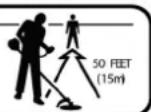
Keep bystanders at least 50 feet (15 m) away during operation.

Beware of thrown or ricocheted objects.

Do not operate this machine with a blade.
IMPORTANT!
The operational procedures described in this manual are intended to help you get the most from your unit as well as to protect you and others from harm. These procedures are guidelines for safe operation under most conditions, and are not intended to replace any safety rules and/or laws that may be in force in your area. If you have questions regarding your 22 Series power tool, or if you do not understand something in this manual, your Shindaiwa dealer will be glad to assist you. You may also contact Shindaiwa, Inc. at the address printed on the back of this Manual.
General Safety Instructions
Work Safely
Shindaiwa trimmers operate at very high speeds and can do serious damage or injury if they are misused or abused. Never allow a person without training or instruction to operate your 22 Trimmer!

WARNING!
Never make unauthorized attachment installations. Do not use attachments not approved by Shindaiwa for use on this unit.
Stay Alert
You must be physically and mentally fit to operate this unit safely.

WARNING!
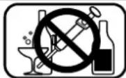
Never operate power equipment of any kind if you are tired or if you are under the influence of alcohol, drugs, medication or any other substance that could affect your ability or judgement.

WARNING!
Minimize the Risk of Fire
NEVER smoke or light fires near the engine.
ALWAYS stop the engine and allow it to cool before refueling. Avoid overfilling and wipe off any fuel that may have spilled.
ALWAYS inspect the unit for fuel leaks before each use. During each refill, check that no fuel leaks from around the fuel cap and/or fuel tank. If fuel leaks are evident, stop using the unit immediately. Fuel leaks must be repaired before using the unit.
ALWAYS move the unit to a place well away from a fuel storage area or other readily flammable materials before starting the engine.
NEVER place flammable material close to the engine muffler.
NEVER run the engine without the spark arrester screen in place.

Figure 1
WARNING!
Use Good Judgment
ALWAYS wear eye protection to shield against thrown objects.
NEVER run the engine when transporting the unit.
NEVER run the engine indoors!
Make sure there is always good ventilation. Fumes from engine exhaust can cause serious injury or death.
ALWAYS clear your work area of trash or hidden debris that could be thrown back at you or toward a bystander.
ALWAYS use the proper cutting tool for the job.
ALWAYS stop the engine immediately if it suddenly begins to vibrate or shake. Inspect for broken, missing or improperly installed parts or attachments.
NEVER extend trimming line beyond the length specified for your unit.
ALWAYS keep the unit as clean as practical. Keep it free of loose vegetation, mud, etc.
ALWAYS hold the unit firmly with both hands when cutting or trimming, and maintain control at all times.
ALWAYS keep the handles clean.
ALWAYS disconnect the spark plug wire before performing any maintenance work.
Wear close-fitting clothing to protect legs and arms.
Gloves offer added protection and are strongly recommended.Do not
wear clothing or jewelry that could get caught in
machinery or underbr
Secure hair so it is above shoulder
level. NEVER wear shorts!
Wear hearing protection devices and a broad-brimmed hat or helmet.
Always wear eye protection such as goggles or safety glasses.
Keep a proper footing and do not overreach—maintain your balance at all times during operation.
Always operate with both hands firmly gripping the unit.
Keep away from the rotating trimmer line at all times, and never lift a moving attachment above waist-high.
Always make sure the appropriate cutting attachment shield is correctly
installed and in good condition.
Wear appropriate footwear (non-skid boots or shoes): do not wear open-toed shoes or sandals. Never operate the unit while barefoot!
Avoid long-term operation in very hot or very cold weather.
Make sure bystanders or observers outside the 50-foot "danger zone" wear eye protection.
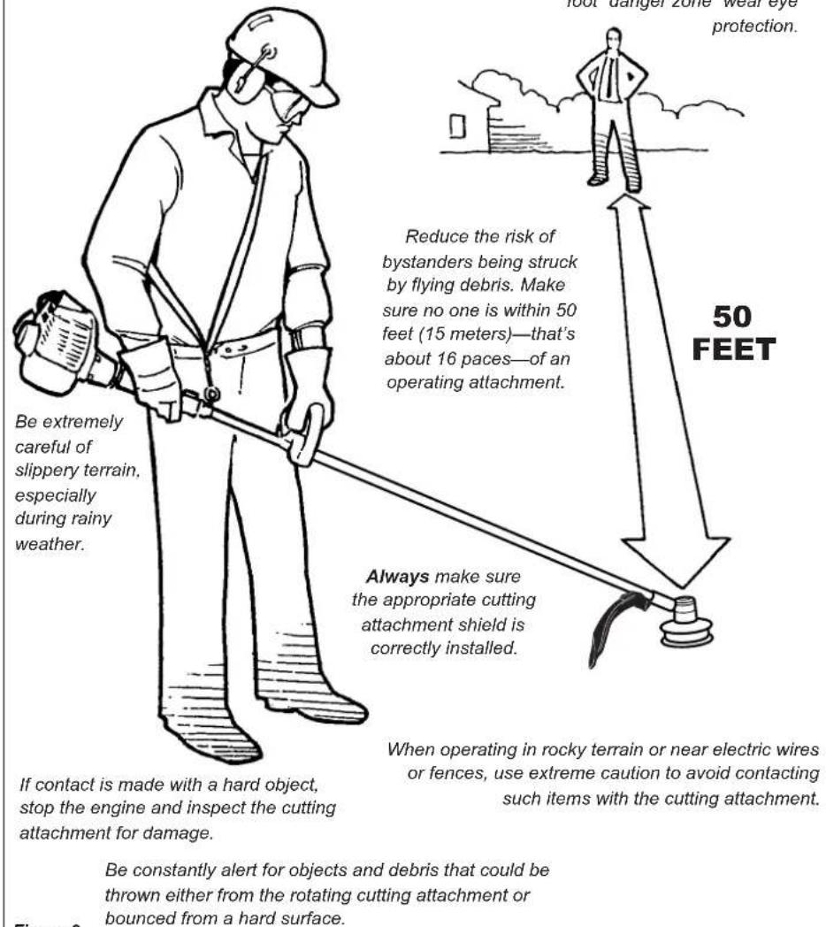
Figure 2
Safety Labels
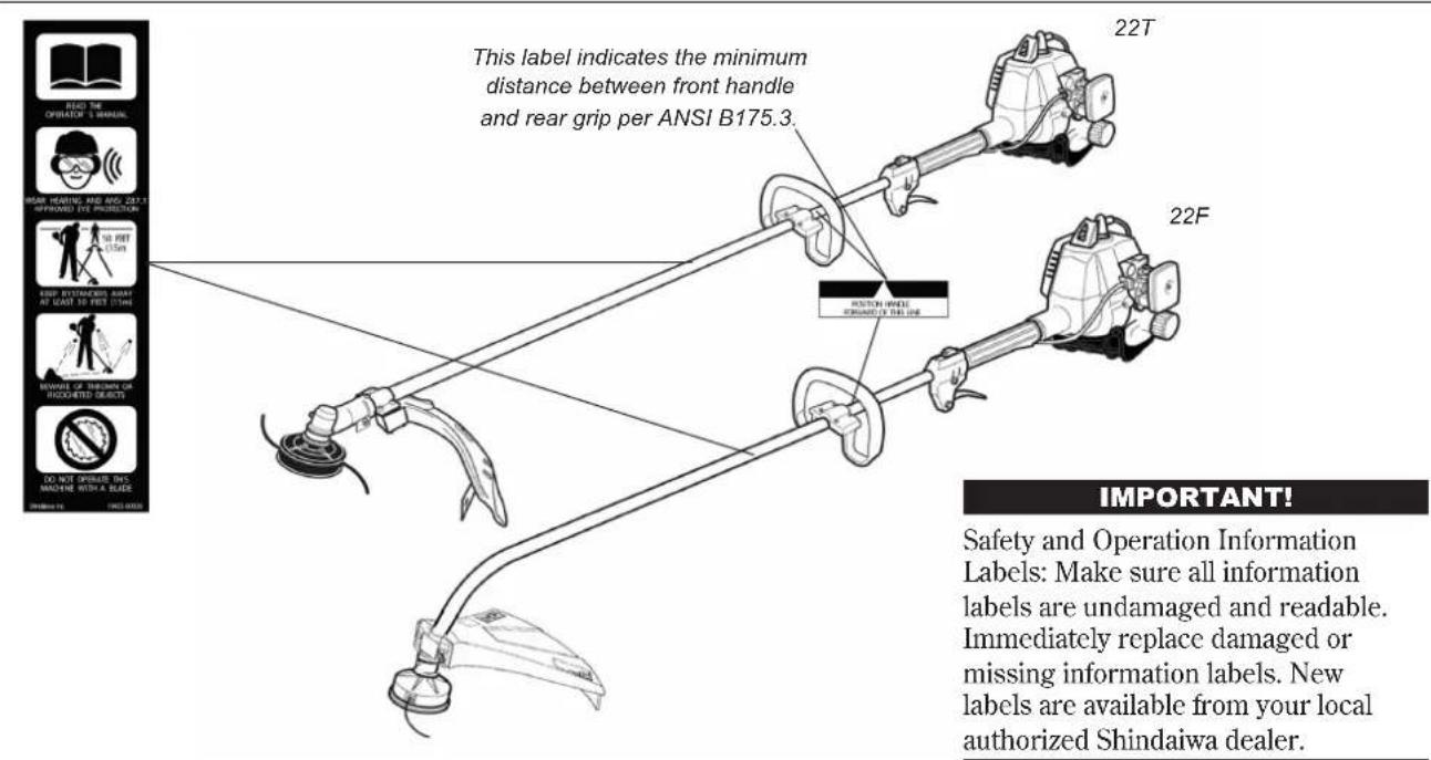
Figure 3
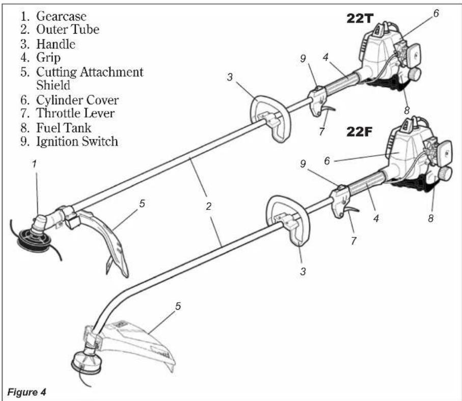
Using the illustrations in this manual as a guide, familiarize yourself with your unit and its various components. Understanding your unit helps ensure top performance, long service life, and safer operation.

WARNING!
Do not make unauthorized modifications or alterations to either of these units or their components.
Specifications
Engine Model.. S220
Engine Type 2-cycle, vertical cylinder, air cooled
Dry weight, 22T
(excluding guard and
cutting attachment) .4.1 kg/9.0 lb
Dry weight, 22F
(excluding guard and
cutting attachment) 4.2kg / 9.3lb
Bore x Stroke 31 mm x 28 mm/1.22" x 1.10"
Displacement 21.1 cc/1.29 cu.in.
Maximum Power
Output .0.9 hp/0.7 kw @ 7500 rpm (min-1)
Transmission Type ....Automatic,centrifugal clutch with bevel gear
Fuel/Oil Ratio 50:1 with Shindaiwa Premium 2-cycle Engine Oil
Fuel Tank Capacity .400 ml/13.6 ounces
Carbureton .Walbro WYL (w/primer)
Ignition System Electronic
Spark Plug.......Champion CJ-8.
For electromagnetic
compliance (EMC) use
NGK BMR6A
Air Cleaner Semi-wet type
Starting Method . . . . . . . . . . . . . . . . . . . . . . . . . . . . . . . . . . . . . . Recoil Starter
Stopping Method.........Slide switch
Handle .........Loop type
EPA Emission
Compliance Period* .......Category B
- The EPA emission compliance referred to on the emission compliance label located on the engine, indicates the number of operating hours for which the engine has been shown to meet Federal emission requirements. Category C = 50 hours (Moderate), B = 125 hours (Intermediate) and A = 300 hours (Extended).
Specifications are subject to change without notice.
Inspect
The 22F and 22T come fully assembled with the exception of the cutting attachment shield and cutting attachment. Before completing the assembly, carefully inspect the unit and all components for any damage and make sure all components are there.
Prior to Assembly
Before assembling, make sure you have all the components required for a complete unit:
Engine and shaft assembly
Cutting attachment shield
Cutting attachment
Kit containing cutting attachment shield
mounting bracket and hardware, this owner/operator's manual and tool kit for routine maintenance. Tool kits vary by model and may include a hex wrench set, a spark plug/screwdriver combination wrench, and a spanner.
IMPORTANT!
The terms "left", "left-hand", and "LH"; "right", "right-hand", and "RH"; "front" and "rear" refer to directions as viewed by the operator during normal operation.
Assembly and Adjustments Handle
Handle.
- The handle is attached to the outer tube at the factory and positioned vertically. See Figure 5.
- Loosen the 4 screws on the handle and rotate the handle 90 degrees. See Figure 5.
- Position the handle forward of the Handle Positioning Label at the best position for operator comfort (usually about 10 inches ahead of the throttle housing).
- Secure the handle by alternately tightening the four screws in a diagonal or "criss-cross" fashion.
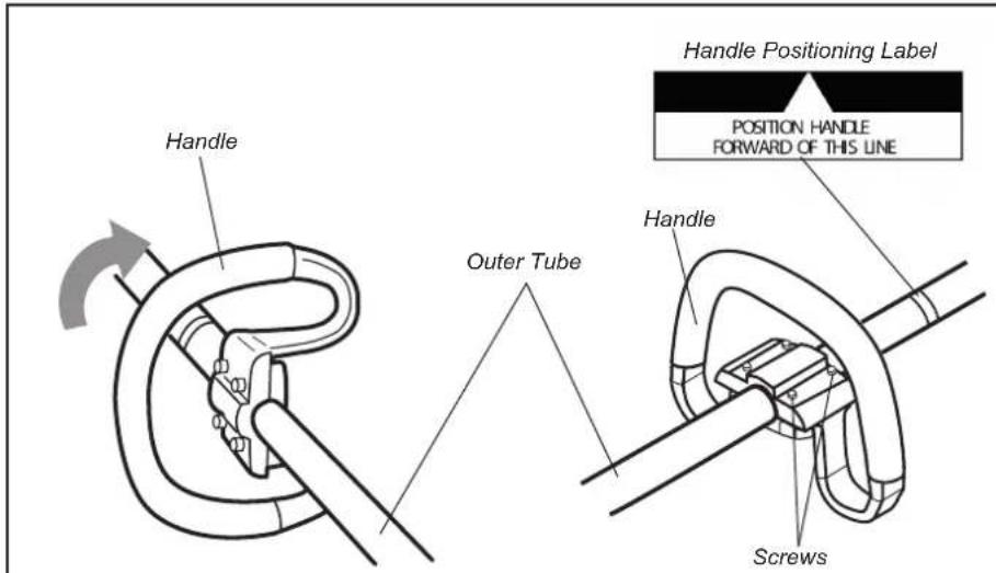
Figure 5
Assembly and Adjustments Adjust Throttle Lever Free Play
Adjust Throttle Free Play
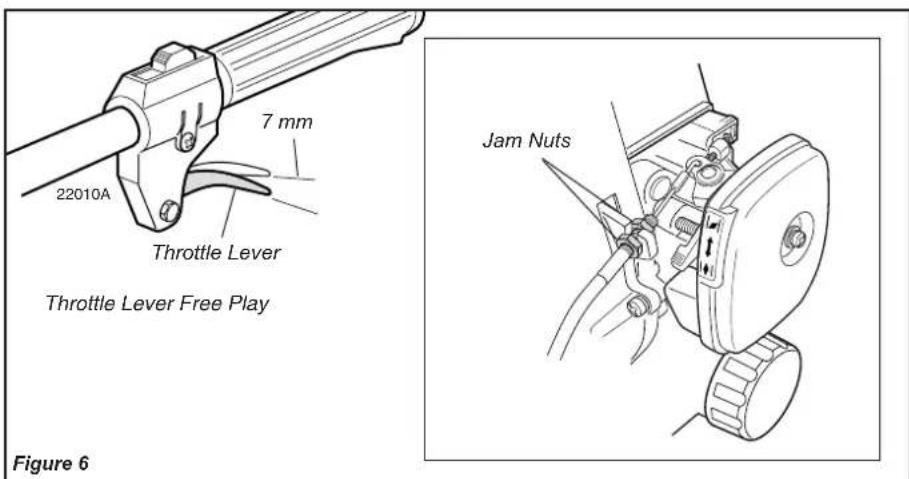
The throttle lever free play should be approximately 7mm . Make sure that the throttle lever operates smoothly without binding. If it becomes necessary to adjust the lever's free play, refer to the illustration and proceed as follows:
- Loosen the cable jam nuts to free the cable from the support.
- Adjust the jam nuts until the throttle lever has approximately 7mm of free play.
- Tighten the jam nuts to secure the cable assembly to the support.
Assembly and Adjustments 22F Cutting Attachment Shield Installation
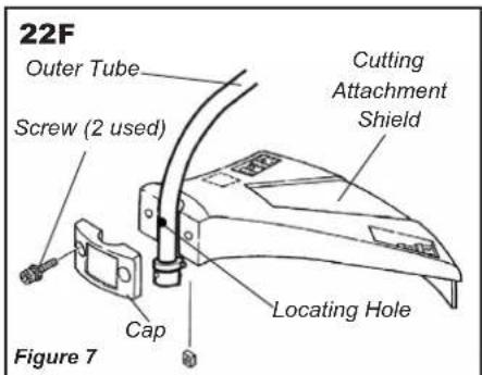
- Install the shield and clamp as shown in Figure 7.
- Align the hole in the outer tube with the locator on the cap; install the two (2) screws finger tight.
- Tighten the screws alternately to secure the cutting attachment shield in place.

WARNING!
NEVER operate the 22F
without the cutting attachment shield installed and tightly secured!
Assembly and Adjustments 22T Cutting Attachment Shield Installation
Install the Cutting Attachment Shield
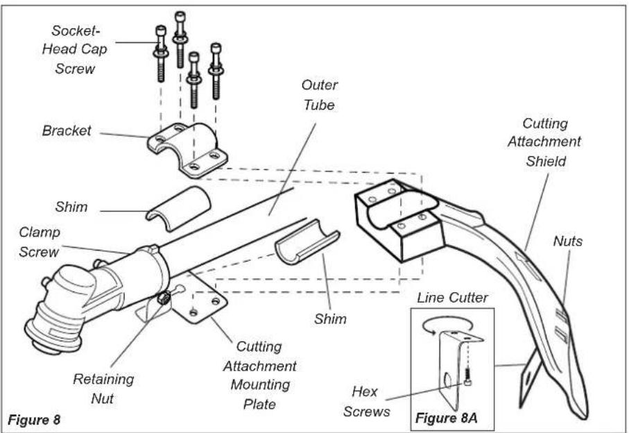
- Insert the cutting attachment shield between the outer tube and the cutting attachment mounting plate. See Figure 8.
NOTE:
It may be necessary to loosen the retaining nut and clamp screw to adjust cutting attachment shield mounting plate.
Fit the two shims and the bracket over the outer tube and loosely install the four socket-head screws. See Figure 8.
CAUTION!
Make sure the clamp screw and retaining nut are securely tightened before tightening the four socket head cap screws.

WARNING!
NEVER operate the 22T
without the cutting attachment shield installed and tightly secured!
The line cutter can be positioned in 2 positions to obtain different line length for cutting.

WARNING!
The line cutter is very sharp. Wear gloves to protect your hands when handling.
To Change Position of Line Cutter.
- Remove the 2 hex screws with a 4mm hex wrench. See Figure 8A.
- Rotate line cutter. See Figure 8A.
- Reinstall the two hex screws and tighten them securely.
NOTE:
Be careful to not lose the 2 nuts in the cutting attachment shield, they are not captured.
Assembly Trimmer Head Installation
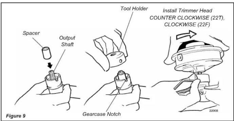
- Position the trimmer with the gearcase output shaft pointing up; as shown in the illustration.
- Install the spacer onto the output shaft.
- Install the tool holder and align the hole on the side of the holder with the notch on the gearcase; as shown in the illustration.
- Insert a 4mm hex wrench through the tool holder hole and the gearcase notch to lock the tool holder to the gearcase.
- While holding the tool holder locked with the 4mm hex wrench, thread the trimmer head onto the output shaft.
- Remove the hex wrench to unlock the tool holder. Rotate the trimmer head by hand to ensure that it does not bind and rotates freely.
CAUTION!
Some gasolines contain alcohol as an oxygenate! Oxygenated fuels may cause increased operating temperatures. Under certain conditions, alcohol-based fuels may also reduce the lubricating qualities of some mixing oils. Never use any fuel containing more than 10% alcohol by volume! Generic oils and some outboard motor oils may not be intended for use in high-performance air-cooled 2-cycle engines, and should never be used in your Shindaiwa engine.
CAUTIONI
This engine is designed to operate on a 50:1 mixture consisting of unleaded gasoline and premium 2-cycle mixing oil only.
Use only fresh, clean unleaded gasoline with a pump octane of 87 or higher.
Mix all fuel with a premium 2-cycle air-cooled mixing oil at a 50:1 gasoline/ oil ratio.
Examples of 50:1 mixing quantities
1 gallon of gasoline to 2.6 oz. mixing oil
5 liters of gasoline to 100ml mixing oil
IMPORTANT!
Mix only enough fuel for your immediate needs! If fuel must be stored longer than 30 days and ONE oil with fuel stabilizer is not used, it should first be treated with a fuel stabilizer such as StaBilTM.

WARNING!
Minimize the risk of fire!
STOP engine before refueling.
ALWAYS allow the engine to cool before refueling!
Wipe all spilled fuel and move the engine at least 10 feet (3 meters) from the fueling point and source before restarting!
NEVER start or operate this unit if there is a fuel leak.
NEVER start or operate this unit if the carburetor, fuel lines, fuel tank and/or fuel tank cap are damaged.
NEVER smoke or light any fires near the engine or fuel source!
NEVER place any flammable material near the engine muffler!
Never operate the engine without the muffler and spark arrester in good working condition.
- Place the trimmer on a flat, level surface.
- Clear any dirt or other debris from around the fuel filler cap.
- Remove the fuel cap, and fill the tank with clean, fresh fuel.
- Reinstall the fuel filler cap and tighten firmly.
Starting the Engine
Starting a Cold Engine
IMPORTANT!
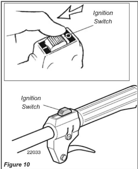
Engine ignition is controlled by a two-position on-off switch mounted on the throttle body. This switch is typically labeled "I" for START and "O" for STOP.
- Slide the ignition switch to the "T" (ON) position.
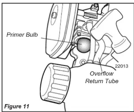
- Prime the engine by repeatedly pressing and releasing the carburetor primer bulb until fuel can be seen flowing through the transparent overflow return tube.
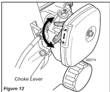
- Close the carburetor's choke by moving the choke lever up toward the spark plug.
WARNING!
KEEP WELL CLEAR OF THE TRIMMER HEAD-IT MAY ROTATE WHEN THE ENGINE IS STARTED!
Place the trimmer on the ground during starting.
Make sure you have secure footing and keep a firm grip on the unit.
- Keep bystanders and pets clear when starting.
- Never operate the trimmer unless the trimmer head is installed!
Starting a Warm Engine
When starting a warm engine, perform steps one and two and make sure that the choke lever is in the down position (open the choke).
IMPORTANT!
The primer system only pushes fuel through the carburetor. Repeatedly pressing the primer bulb will not flood the engine with fuel.
- Hold the outer tube firmly with your left hand and use your
right hand to pull the starter handle slowly upward until you feel the starter engage.
- To start the trimmer, pull the starter handle upward rapidly.
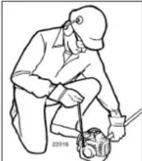
Figure 13
IMPORTANT!
The recoil starter will provide trouble free operation if the following recommendations are observed:
Always engage the starter before attempting to start the engine.
- Never pull the starter cord to its full length.
Always rewind the starter cord slowly.
After the engine starts or fires
- Open the choke by moving the choke lever down (toward the fuel tank).
- If the engine stops, repeat the starting procedure previously described.
- When the engine starts, clear excess fuel from the combustion area by revving the engine several times with the throttle lever.

WARNING!
The trimmer head will rotate as the engine accelerates!
IMPORTANT!
Operating the throttle will automatically disengage the fast idle setting.
If the engine does not start
Repeat the appropriate starting procedures for a hot or cold engine. If the engine still fails to start, use the procedure for "Starting a Flooded Engine."
Starting a Flooded Engine
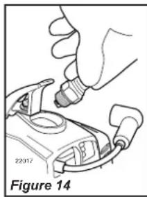
- Disconnect the spark plug boot and unscrew the spark plug using the spark plug wrench provided with the unit (turn counterclockwise to remove).
-
If the spark plug is fouled with carbon or coated with fuel, clean or replace the spark plug as necessary. For spark plug specifications and gapping procedure, refer to page 11.
-
Crank the engine several times to clear excess fuel from the combustion chamber, making sure that the choke is open and the ignition switch is in the "O" (STOP) position.
CAUTION!
Incorrect spark plug installation can result in serious engine damage!
- Install the spark plug and tighten same using the spark plug wrench provided with the unit. If a torque wrench is available, torque the spark plug to 148-165 inch-pounds (170 - 190kg / cm)
- Repeat the starting procedures for a warm engine.
- If the engine still fails to start or fire, refer to the troubleshooting chart at the end of this manual.
Stopping the Engine
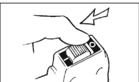
Figure 15
- Let the engine idle for a period of two to three minutes to allow engine to cool and temperature to stabilize.
- Slide the ignition switch to the "O" (STOP) position.
Engine Idle
Checking and Adjusting
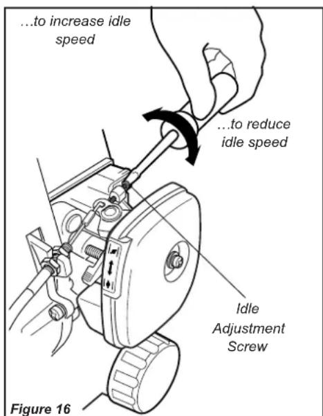
The engine must return to idle speed whenever the throttle lever is released. Engine idle speed is adjustable and must be properly set to permit the clutch shoes to disengage from the clutch drum. The correct engine idle speed also provides air flow to maintain engine cooling.
Idle Adjustment Procedure
-
Start the engine and allow it to idle for two to three minutes until it warms up.
-
If the cutting attachment rotates at engine idle speed, turn the idle speed adjustment screw counterclockwise until the cutting attachment stops turning.
- If a tachometer is available, the engine idle speed should be final-adjusted to 3000rpm± 250rpm (min^1)

WARNING!
The cutting attachment must NEVER rotate at engine idle speeds! If the idle speed cannot be adjusted by the above procedure, return the trimmer to your Shindaiwa dealer for inspection.
CAUTION!
Carburetor mixture adjustments are set at the factory and cannot be serviced in the field.
Never operate the unit with the cutting attachment shield or other protective devices removed!

WARNING!
A cutting attachment shield or other protective device is no guarantee of protection against thrown objects. YOU MUST ALWAYS GUARD AGAINST FLYING DEBRIS!
Use only authorized Shindaiwa parts and accessories with your Shindaiwa trimmer. Do not make modifications to the unit without the written approval of Shindaiwa, Inc.
ALWAYS make sure the trimmer head is properly installed and firmly tightened before operation.
NEVER use a cracked, warped, or worn out trimmer head: replace it with a serviceable one.
ALWAYS make sure the trimmer head fits properly into the appropriate holder. If a properly installed head vibrates, replace it with new one and recheck its operation.
ALWAYS stop the engine immediately and check for damage if you strike a foreign object or if the trimmer head becomes entangled. Do not operate with broken or damaged equipment.
NEVER allow the engine to run at high speed without a load. Engine operation at high speed without a load could damage the engine.
NEVER operate a unit with worn or damaged fasteners or attachment holders.
Cutting Grass
Your Shindaiwa 22T/22F grass trimmer is equipped with a semi-automatic nylon trimmer head.
Engine Operating Speeds
Operate the unit at full throttle while cutting grass.
CAUTION!
Do not push the rotating line into trees, wire fences or any material that could tangle or break the nylon lines.
CAUTION!
Operation of trimmer without a cutting attachment shield and using excessive line length can lead to premature clutch failure.
CAUTION!
Operation at low rpm can lead to premature clutch failure.
Trimming and Mowing Grass
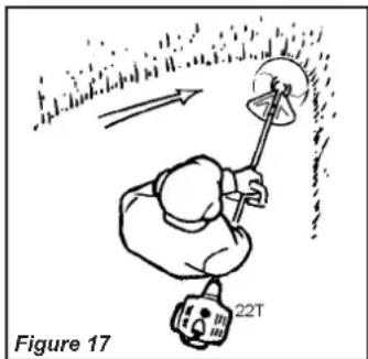
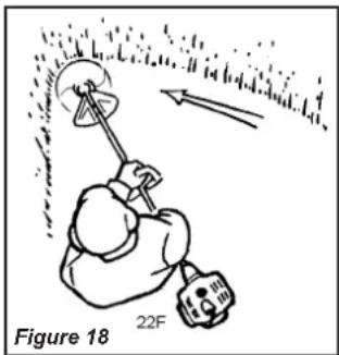
Hold the grass trimmer as shown in the above illustration. The trimmer head should be angled slightly into the area to be cut. To ensure maximum trimmerline service life, cut only with the tip of the trimmer line. Sweep the trimmer head left to right (22T), and right to left (22F) to trim the grass. During cutting operations, the trimmer head should be kept horizontal to the ground at all times.
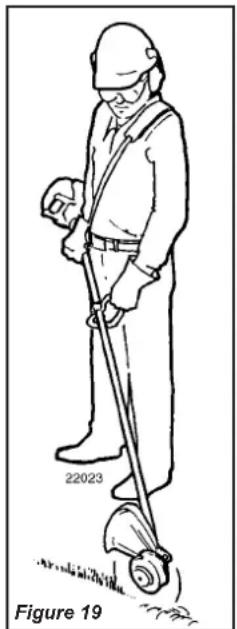
Edging
Tilt the handle approximately 100 degrees to the right (from horizontal) and move forward while holding the trimmer vertical.
IMPORTANT!
MAINTENANCE, REPLACEMENT OR REPAIR OF EMISSION CONTROL DEVICES AND SYSTEMS MAY BE PERFORMED BY ANY REPAIR ESTABLISHMENT OR INDIVIDUAL. ALL WARRANTY REPAIRS MUST BE PERFORMED BY A DEALER OR SERVICE CENTER AUTHORIZED BY SHINDAIWA CORPORATION THE USE OF PARTS THAT ARE NOT EQUIVALENT IN PERFORMANCE AND DURABILITY TO AUTHORIZATION PARTS MAY IMPAIR THE EFFECTIVENESS OF THE EMISSION CONTROL SYSTEM AND MAY HAVE A BEARING ON THE OUTCOME OF A WARRANTY CLAIM.

WARNING!
Before performing any maintenance, repair or cleaning work on the unit, make sure the engine and cutting attachment are completely stopped. Disconnect the spark plug wire before performing service or maintenance work.

WARNING!
Non-standard parts may not operate properly with your unit and may cause damage and lead to personal injury.
NOTE:
Using non-standard replacement parts could invalidate your Shindaiwa warranty.
Muffler

WARNING!
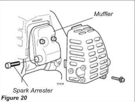
Never operate this unit with a damaged or missing muffler or spark arrester! Operating with missing or damaged exhaust components is a fire hazard, and may also damage your hearing.
Hard starting or a gradual loss of performance may be caused by carbon deposits lodged in the muffler's spark arrester screen. In such cases, performance can usually be restored by removing the spark arrester screen and giving it a thorough cleaning with a stiff bristle brush.
In case of heavy carbon deposits or when there is no improvement in performance after cleaning the spark arrester screen, consult with your nearest Shindaiwa dealer.
Spark Plug
Keep the spark plug and wire connections tight and clean.
Fasteners
Make sure nuts, bolts, and screws (except carburetor adjusting screws) are tight.
Daily Maintenance
Prior to each work day, perform the following:
Remove any dirt and debris from the engine, check the cooling fins and air cleaner for clogging, and clean them as necessary.
Carefully remove any accumulations of dirt or debris from the muffler and fuel tank. Dirt buildup in these areas can lead to engine overheating, premature wear or fire.
Check for loose or missing screws or components. Make sure the trimmer head is securely fastened.
Check the unit for leaking fuel or grease.
10-Hour Maintenance
Every 10 hours of operation...
(more frequently in dusty or dirty conditions):
Remove the air cleaner element from the carburetor and wash it with soap and water. Rinse the element thoroughly with clean water.
Squeeze out the water and allow the element to dry before reinstalling.
10/15-Hour Maintenance
CAUTION!
Do not operate the unit if the air cleaner or element is damaged, or if the element is wet.
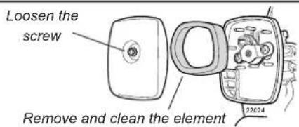
Figure 21
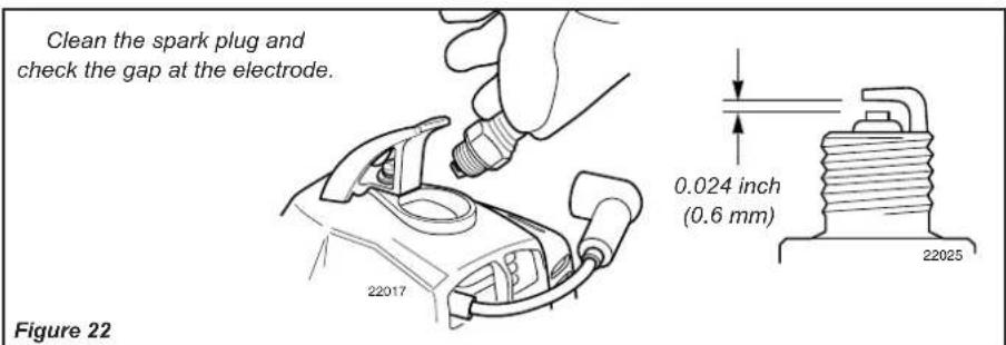
Every 10 to 15 hours of operation: Remove and clean the spark plug. Adjust the spark plug electrode gap to 0.024-inch (0.6mm) .If the plug must be replaced, use only a Champion CJ8 or equivalent type spark plug of the correct heat range.For Electromagnetic Compliance (EMC) use NGK BMR6A.See Figure 22.
CAUTION!
Before removing the spark plug, clean the area around the plug to prevent dirt and debris from getting into the engine's internal parts.
Every 50 hours of operation (more frequently in dusty or dirty conditions):
Remove and clean the cylinder cover and clean grass and dirt from the cylinder fins.
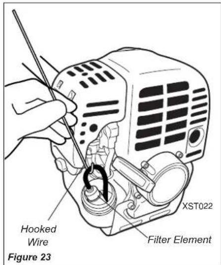
Use a hooked wire to extract the fuel filter from inside the fuel tank. See Figure 23.
CAUTION!
Make sure you do not pierce the fuel line with the end of the hooked wire. The line is delicate and can be damaged easily.
Remove and replace the filter element. Before reinstalling the new filter element, inspect the condition of all the fuel system components (fuel pick-up line, fuel return line, tank vent line, tank vent, fuel cap and fuel tank). If damage, splitting or deterioration is noted, the unit should be removed from service until it can be inspected or repaired by a Shindaiwa-trained service technician.
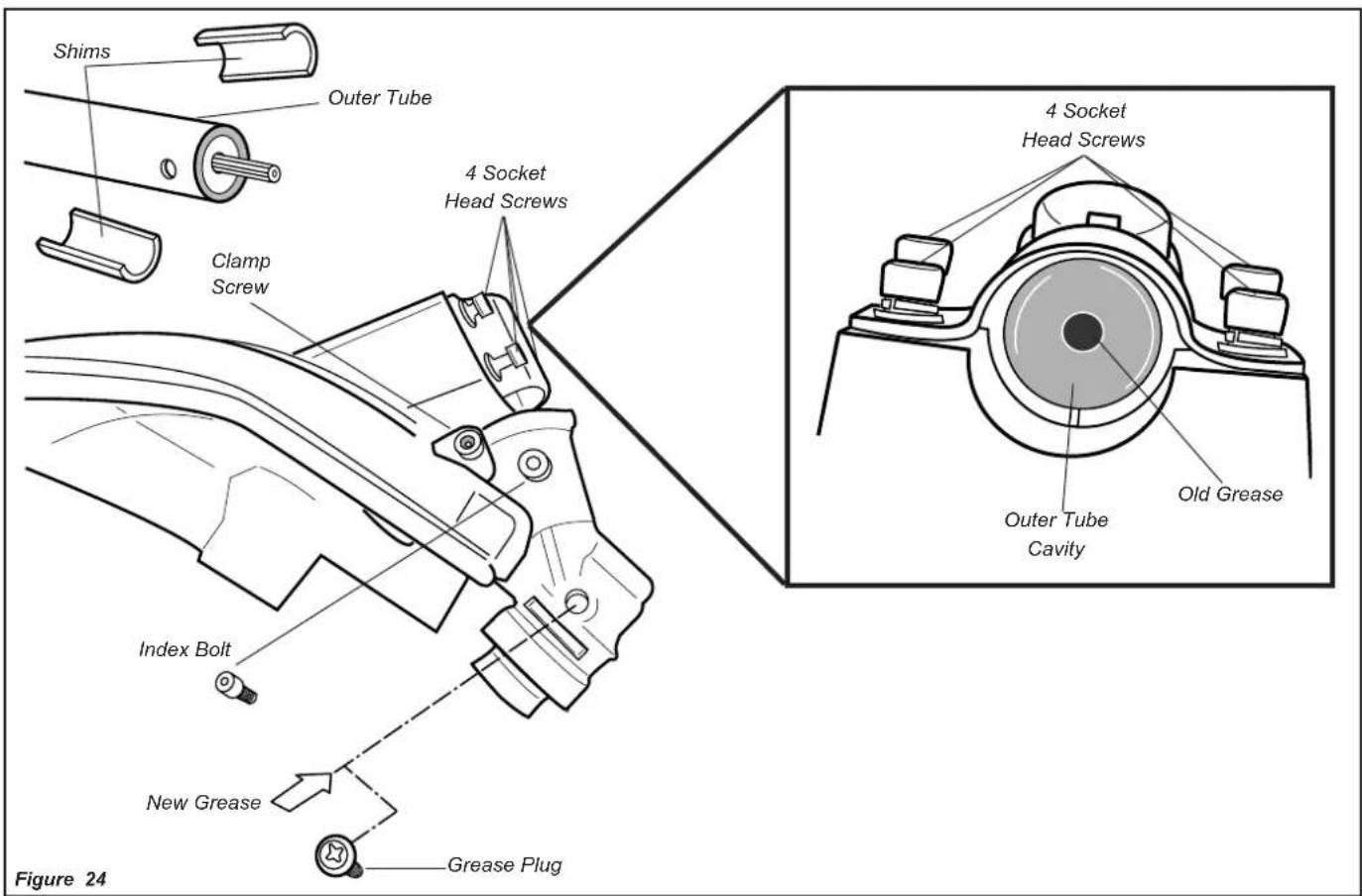
Gearcase Lubrication (22T Only)
- To perform this operation, first remove the gearcase and debris shield from the outer tube as follows. See Figure 24.
CAUTION!
Do not remove the D-shaped shim washer! The shim washer prevents damage from overtightening the tube clamp screw.
Remove the index bolt from the gearcase.
Loosen the gearcase clamp screw.
Loosen the four socket head cap screws that secure the cutting attachment shield.
- Slide the gearcase and cutting attachment shield off the tube. (Do not lose the two shims).
-
Remove the filler plug and press new grease into the gearcase until old grease is purged from the gearcase, which can be seen in the outer tube cavity.
-
Clean up the excess grease and reinstall the cutting attachment shield, two shims and the gearcase.
Long Term Storage
Whenever the unit will not be used for 30 days or longer, use the following procedures to prepare it for storage:
Clean external parts thoroughly.
Drain all the fuel from the fuel tank.
IMPORTANT!
All stored fuels should be stabilized with a fuel stabilizer such as STA-BIL™, if ONE oil with fuel stabilizer is not used.
CAUTION!
Gasoline stored in the carburetor for extended periods can cause hard starting and could also lead to increased service and maintenance cost.
To remove the remaining fuel from the fuel lines and carburetor and with the fuel drained from the fuel tank.
- Prime the primer bulb until no more fuel is passing through.
- Start and run the engine until it stops running.
-
Repeat steps 1 and 2 until the engine will no longer start.
-
Remove the spark plug and pour about 1/4 ounce of 2-cycle mixing oil into the cylinder through the spark plug hole. Slowly pull the recoil starter 2 or 3 times so oil will evenly coat the interior of the engine. Reinstall the spark plug.
Before storing the unit, repair or replace any worn or damaged parts.
Remove the air cleaner element from the carburetor and clean it thoroughly with soap and water. Let dry and reassemble the air cleaner.
Store the unit in a clean, dust-free area.
Troubleshooting Guide
| TROUBLE SHOOTING THE ENGINE | ||
| PROBLEM | PROBABLE CAUSE | CORRECTIVE ACTION |
| Engine won't start or starts but will not run. | Incorrect starting procedures. | Follow the starting procedures outlined in page 8 of this manual. |
| Fouled spark plug. | Clean/gap or replace spark plug. | |
| Fuel filter plugged. | Replace fuel filter. | |
| Choke lever in the start (up) position. | Move choke lever to the run (down) position. | |
| The ignition switch is in "O" (OFF) position. | Move switch to "I" (ON) position and restart. | |
| Engine starts, but has low power. | Spark arrester screen clogged with carbon. | Clean/replace spark arrester screen. |
| Dirty air filter. | Remove, clean and reinstall filter. | |
| Incorrect carburetor mixture adjustment setting. | Consult with an authorized servicing dealer. | |
| Engine hesitates or low power output. | Plugged spark arrester screen, exhaust port ot muffler. | Consult with an authorized servicing dealer |
| Incorrect carburetor mixture adjustment setting. | Consult with an authorized servicing dealer. | |
| Runs erratically. | Incorrectly gapped or faulty spark plug. | Clean/gap or replace plug. |
| Smokes excessively. | Incorrect carburetor mixture adjustment setting. | Consult with an authorized servicing dealer |
| Incorrect fuel / oil mixture. | Use properly mixed fuel (50:1 mixture). | |
| Engine is overheating. | Trimmer line is too long. | Shorten trimmer line. |
| Carburetor mixture is too lean. | Consult with an authorized servicing dealer | |
| Fan, fan cover, cylinder fins dirty or damaged. | Clean, repair, or replace as necessary. | |
| Carbon deposits on the piston or in the muffler. | Consult with an authorized servicing dealer | |
TROUBLE SHOOTING THE TRIMMER HEAD
| PROBLEM | PROBABLE CAUSE | CORRECTIVE ACTION |
| Line won't feed. | Line is tangled inside trimmer head. | Remove spool from unit; disassemble. Untangle line, wind correctly in direction indicated on spool. |
| Upon removing spool, line appears to be melted together. | Trim off damaged line and rewind line. | |
| Line wound in wrong direction inside trimmer head. | Remove spool and wind line in direction indicated on line element. | |
| Insufficient line inside trimmer head. | Remove spool and install new line. | |
| Internal damage to trimmer head caused by bumping too hard on ground while advancing line. | Disassemble trimmer head and examine parts for damage. Replace parts or entire head. | |
| Line snaps off or frays. | Improper trimming procedures, or poor quality line. | See General Trimming instructions or replace line. |
| Trimmer head and shaft | Weed wrap. | Remove weed wrap. |
Emission System Warranty Statement
The following statement only applies to United States and its territories
Shindaiwa Corporation
Federal Emission Design And Defect Limited Warranty Utility And Lawn And Garden Engines
Shindaiwa Corporation warrants to the initial purchaser and each subsequent owner, that this utility equipment engine (herein engine) is designed, built and equipped to conform at the time of initial sale, to all applicable regulations of the U.S. Environmental Protection Agency (EPA), and that the engine is free of defects in materials and workmanship that would cause this engine to fail to conform with EPA regulations during its warranty period. This emission warranty is applicable in all States, except the State of California.
For parts listed under PARTS COVERED, the dealer authorized by Shindaiwa Corporation will, at no cost to you, make the necessary diagnosis, repair, or replacement of any defective emission-related component to ensure that the engine complies with applicable U.S. EPA regulations.
MANUFACTURERS WARRANTY COVERAGE
When sold within the U.S., this engine's emission control system is warranted for a period of two (2) years from the date this product is first delivered to the original retail purchaser.
OWNER'S WARRANTY RESPONSIBILITIES
As the engine owner, you are responsible for the performance of the required maintenance listed in your owner's manual. Shindaiwa Corporation recommends that you retain all receipts covering maintenance on your engine, but Shindaiwa Corporation cannot deny a warranty claim solely for the lack of receipts or for your failure to ensure the performance of all scheduled maintenance.
As the engine owner, you should however be aware that Shindaiwa Corporation may deny your warranty coverage if your engine or a part has failed due to abuse, neglect, improper maintenance or unapproved modifications.
You are responsible for presenting your engine to the nearest dealer authorized by Shindaiwa Corporation when a problem exists.
If your Shindaiwa Dealer is unable to answer questions regarding your warranty rights and responsibilities, you should then contact your Shindaiwa Distributor.
For the name and telephone number of the Shindaiwa Distributor in your area, please call Shindaiwa Inc. at (503) 692-3070 between the hours of 8:00 AM and 5:00 PM Pacific Standard Time.
PARTS COVERED
Listed below are the parts covered by the Federal Emission Design and Defect Warranty. Some parts listed below may require scheduled maintenance and are warranted up to the first scheduled replacement of that part. The warranted parts include:
- Carburctor Internal Components
- Valve Assembly-throttle, Jet, Metering Diaphragm
- Ignition System Components
- Ignition Coil
Flywheel Rotor
The emission control system for your particular Shindaiwa engine may also include certain related hoses and connectors.
LIMITATIONS
The Federal Emission Design and Defect Warranty shall not cover any of the following:
(a) conditions resulting from tampering, misuse, improper adjustment (unless they were made by the dealer or service center authorized by Shindaiwa Corporation during a warranty repair), alteration, accident, failure to use the recommended fuel and oil, or not performing required maintenance services,
(b) the replacement parts used for required maintenance services,
(c) consequential parts used for required maintenance services,
(d) diagnosis and inspection fees that do not result in eligible warranty service being performed, and
(c) any non-authorized replacement part, or malfunction of authorized parts due to use of non-authorized parts.
MAINTENANCE AND REPAIR REQUIREMENTS
You are responsible for the proper use and maintenance of the engine. You should keep all receipts and maintenance records covering the performance of regular maintenance in the event questions arise. These receipts and maintenance records should be transferred to each subsequent owner of the engine. Shindaiwa Corporation reserves the right to deny warranty coverage if the owner has not properly maintained the engine. Shindaiwa Corporation will not deny warranty repairs, however, solely because of the lack of repair, maintenance or failure to keep maintenance records.
MAINTENANCE, REPLACEMENT OR REPAIR OF EMISSION CONTROL DEVICES AND SYSTEMS MAY BE PERFORMED BY ANY REPAIR ESTABLISHMENT OR INDIVIDUAL; HOWEVER, WARRANTY REPAIRS MUST BE PERFORMED BY A DEALER OR SERVICE CENTER AUTHORIZED BY Shindaiwa Corporation THE USE OF PARTS THAT ARE NOT EQUIVALENT IN PERFORMANCE AND DURABILITY TO AUTHORIZED PARTS MAY IMPAIR THE EFFECTIVENESS OF THE EMISSION CONTROL SYSTEM AND MAY HAVE A BEARING ON THE OUTCOME OF A WARRANTY CLAIM.
If other than the parts authorized by Shindaiwa Corporation are used for maintenance replacements or for the repair of components affecting emission control, you should assure yourself that such parts are warranted by their manufacturer to be equivalent to the parts authorized by Shindaiwa Corporation in their performance and durability.
OBTAINING WARRANTY SERVICE
All repairs qualifying under this limited warranty must be performed by a dealer authorized by Shindaiwa Corporation
If any emission-related part is found defective during the warranty period, it is your responsibility to present the product to an authorized Shindaiwa dealer. Bring your sales receipts showing the date of purchase for this engine. The dealer authorized by Shindaiwa Corporation will perform the necessary repairs or adjustments within a reasonable amount of time and furnish you with a copy of the repair order. All parts and accessories replaced under this warranty become the property of Shindaiwa Corporation
To locate an authorized Shindaiwa dealer near you, contact your Shindaiwa Distributor. For the name and telephone number of the Shindaiwa Distributor in your area, please call Shindaiwa Inc. at (503) 692-3070 between the hours of 8:00 AM and 5:00 PM Pacific Standard Time.
THIS WARRANTY IS ADMINISTERED BY:
Shindaiwa Inc.
11975 SW Herman Road
Tualatin, Oregon 97062
Fax: 503 692-6696
www.shindaiwa.com
Shindaiwa Corporation
Head Office: 6-2-11 Ozuka-Nishi,
Asaminami-Ku, Hiroshima,
731-3167, Japan
FAX: 81-82-849-2481
©2005 Shindaiwa, Inc.
Part Number 81018
Shindaiwa is a registered trademark.
Specifications subject to change without notice.
A征求意见 of the general public on the proposed legislation was published by the Minister of Education, Science and Technology (Ministry of Education, Science and Technology) in 2014.

Advertencia!
Toda informacion
Potencia .0.9 hp/0.7 kw @ 7500 rpm (min)
Carburant .50:1 with Shindaiwa Premium
2-cycle Engine Oil
compliance (EMC) use
NGK BMR6A
Filtre a air Semi-wet type
Examples of 50:1 mixing quantities
1 gallon of gasoline to 2.6 oz. mixing oil
5 litres of gasoline to 100ml mixing oil
IMPORTANT!
Tualatin, Oregon 97062
©2005 Shindaiwa, Inc.
Piecenuo 81018

shindaiwa
Shindaiwa Inc.
11975 S.W. Herman Road
Tualatin, Oregon 97062
Fax: 503 692-6696
www.shindaiwa.com
Shindaiwa Corporation
Head Office: 6-2-11 Ozuka-Nishi,
Asaminami-Ku Hiroshima,
731-3167, Japan
Fax: 81-82-849-2481
©2005 Shindalwa, Inc.
Part Number 81018
Specifications subject to change without notice.
shindaiwa
Shindaiwa Inc.
11975 SW Herman Road.
Tualatin, Oregon 97062
Fax: 503 692-6696
www.shindaiwa.com
Shindaiwa Corporation
Head Office: 6-2-11 Ozuka-Nishi,
Asaminami-Ku, Hiroshima,
731-3167, Japan
FAX:81-82-849-2481
©2005 Shindaiwa, Inc.
Tualatin, Oregon 97062
©2005 Shindaiwa, Inc.
Piecenumber81018