
ZHC6122X - Basket ZANUSSI - Free user manual and instructions
Find the device manual for free ZHC6122X ZANUSSI in PDF.

| Product type | Extractor hood / recirculation hood |
| Brand | Zanussi |
| Model | ZHC6122X |
| Dimensions (W x D x H) | 598 x 500 x 132 mm |
| Weight | 12 kg |
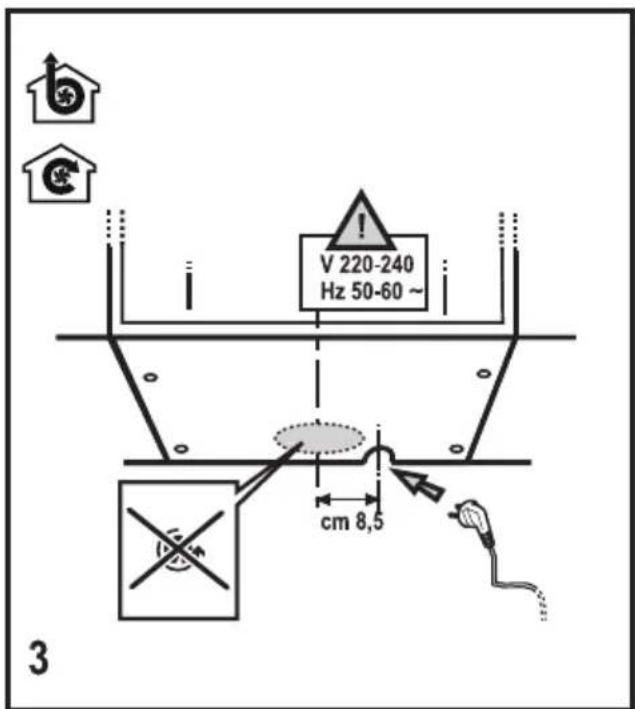
| Power supply | 220-240 V, 50 Hz |
| Suction power | 3 speeds (minimum, medium, maximum) |
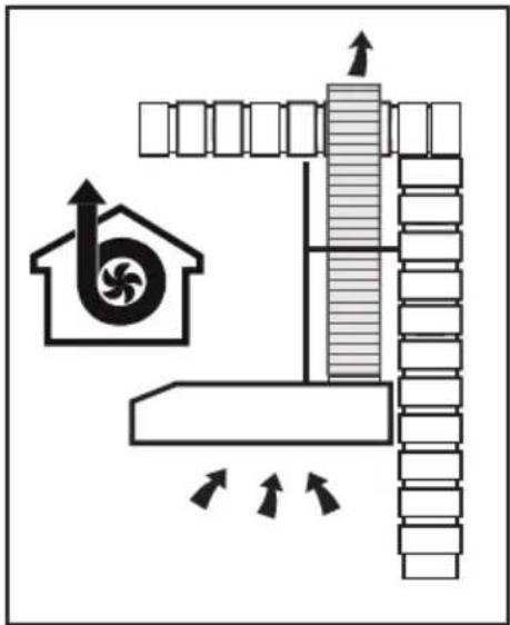
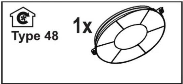
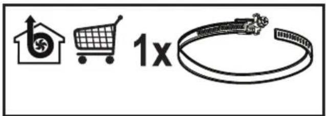
| Installation type | External extraction or internal recirculation |
| Lighting | LED 3W, socket E14 (max) |
| Grease filter | Dishwasher safe, clean once a month |
| Activated carbon filter | Not washable, replace every 4 months |
| Minimum cooking distance | ≥ 50 cm (electric hob) / ≥ 65 cm (gas or mixed hob) |
| Material | Stainless steel |
| Control | Mechanical buttons |
| Main functions | Light ON/OFF control, motor stop, speed selection |
| Safety | Disconnect before maintenance, do not flambé under the hood, ensure sufficient ventilation |
| Exterior maintenance | Damp cloth with mild detergent, no alcohol or abrasives |
| Bulb replacement | LED bulb 3W E14 only |
| Recommended use | Switch on 5 min before cooking, leave on for 15 min after |
| Recycling | Do not dispose with household waste, take to recycling center |
Frequently Asked Questions - ZHC6122X ZANUSSI
User questions about ZHC6122X ZANUSSI
0 question about this device. Answer the ones you know or ask your own.
Ask a new question about this device
Download the instructions for your Basket in PDF format for free! Find your manual ZHC6122X - ZANUSSI and take your electronic device back in hand. On this page are published all the documents necessary for the use of your device. ZHC6122X by ZANUSSI.
USER MANUAL ZHC6122X ZANUSSI
natural_image
Diagram of a building interior with air flow indicators and a fan-shaped structure (no text or symbols)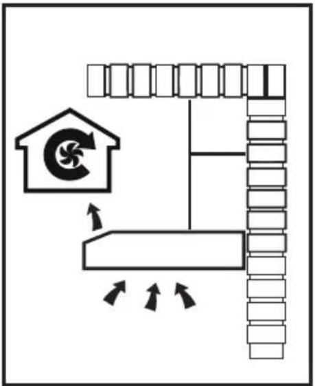
flowchart
graph TD
    A["House Icon"] --> B["Recycle Path"]
    B --> C["Flow Direction Arrows"]
    C --> D["Return to House"]
    style A fill:#f9f,stroke:#333
    style D fill:#bbf,stroke:#333
natural_image
Illustration of a hand using a tool to cut or adjust a mechanical component (no text or symbols visible)natural_image
Technical diagram of a mechanical device with internal components and labeled parts (no readable text or symbols)COMANDI
⚠ SAFETY INFORMATION
Before any cleaning or maintenance operation, disconnect hood from the mains by removing the plug or disconnecting the mains electrical supply.
Always wear work gloves for all installation and maintenance operations.
This appliance can be used by children aged from 8 years and above and per sons with reduced physical, sensory or mental capabilities or lack of experience and knowledge if they have been given supervision or instruction concerning use of the appliance in a safe way and understand the hazards involved.
Children shall not be allowed to tamper with the controls or play with the appliance.
Cleaning and user main te nance shall not be made by children without supervision.
The premises where the appliance is installed must be sufficiently ventilated, when the kitchen hood is used together with other gas combustion devices or other fuels.
The hood must be regularly cleaned on both the inside and outside (AT LEAST ONCE A MONTH).
This must be completed in accordance with the maintenance instructions provided in this manual.
Failure to follow the instruc tions provided in this user guide regarding the cleaning of the hood and filters will lead to the risk of fires.
The flaming of foods beneath the hood itself is severely prohibited.
The use of exposed flames is detrimental to the filters and may cause a fire risk, and must therefore be avoided in all circumstances.
Any frying must be done with care in order to make sure that the oil does not overheat and ignite.
CAUTION: Accessible parts of the hood may become hot when used with cooking appliances. When connecting the hood to the electrical network, only certified electrical adaptors are allowed and not power strips.
SAFETY INSTRUCTIONS
For lamp replacement use only lamp type indicated in the Maintenance/Replacing lamps section of this manual.

WARNING! Do not connect the appliance to the mains until the installation is fully complete.
With regards to the technical and safety measures to be adopted for fume discharging it is important to closely follow the regulations provided by the local authorities.
The ducting system for this appliance must not be connected to any existing ventilation system which is being used for any other purpose such as discharging exhaust fumes from appliances burning gas or other fuels.
Do not use or leave the hood without the lamp correctly mounted due to the possible risk of electric shocks.
Never use the hood without effectively mounted grids.
The hood must NEVER be used as a support surface unless specifically indicated.
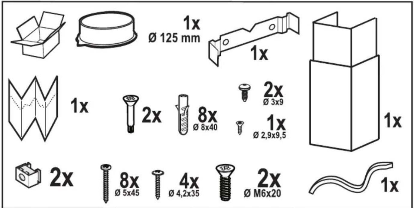
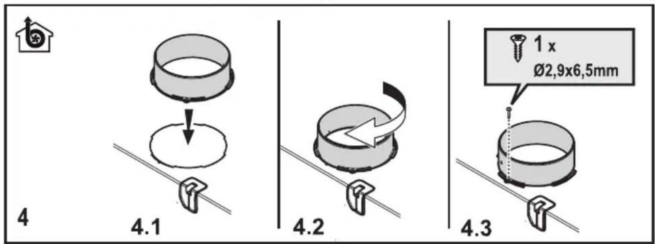
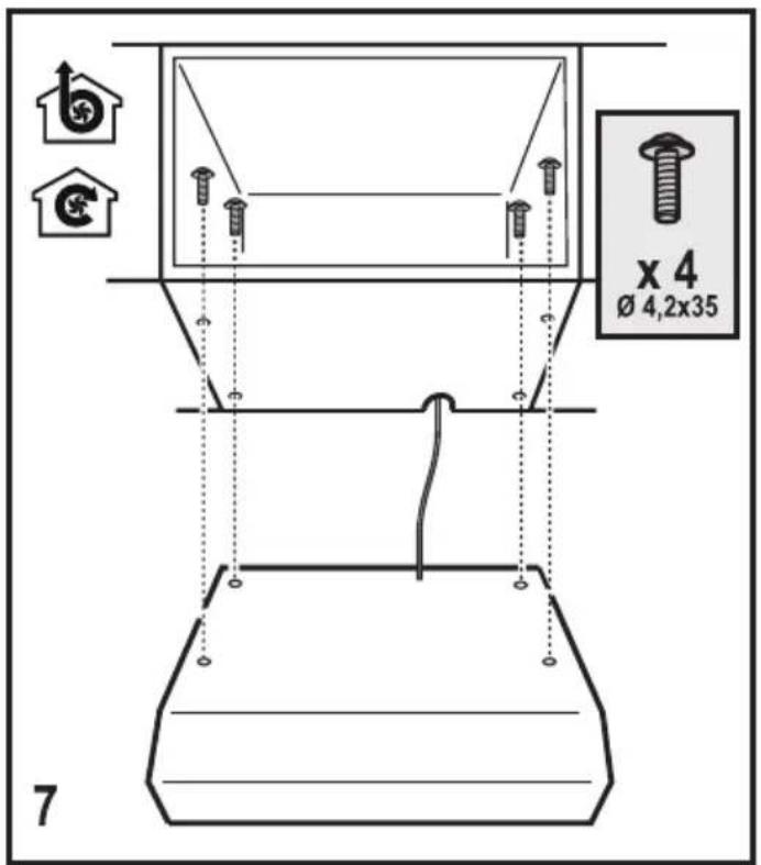
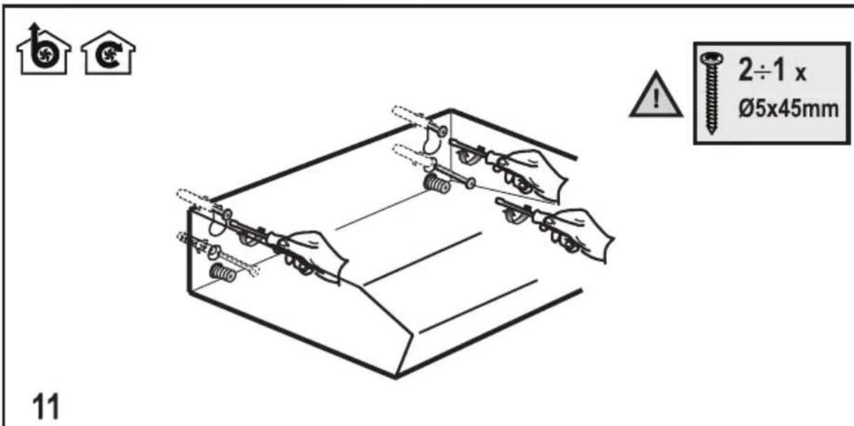
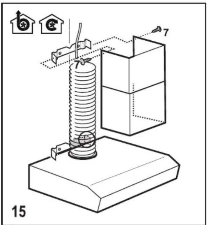
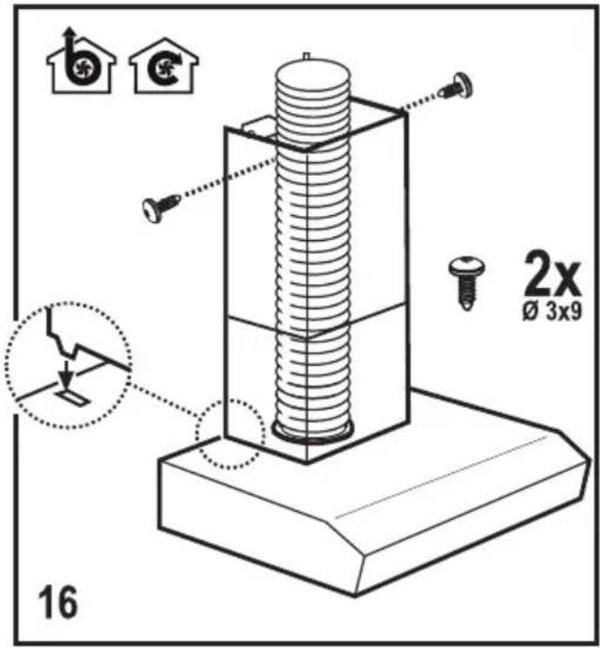
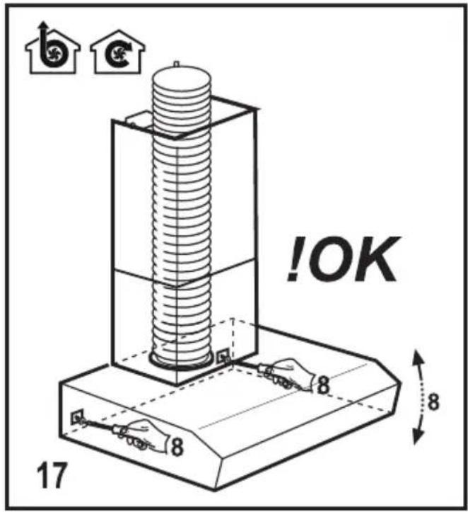
Use only the fixing screws supplied with the product for installation or, if not supplied, purchase the correct screws type.
Use the correct length for the screws which are identified in the Installation Guide.
In case of doubt, consult an authorised service assistance centre or similar qualified person.

WARNING! Failure to install the screws or fixing device in accordance with these instructions may result in electrical hazards.
ENVIRONMENT CONCERNS
Recycle the materials with the symbol
. Put the packaging in applicable containers to recycle it. Help protect the environment and human health and to recycle waste of electrical and electronic appliances. Do not dispose appliances
marked with the symbol with the household waste. Return the product to your local recycling facility or contact your municipal office department for household waste or the shop where you purchased this product.
USE
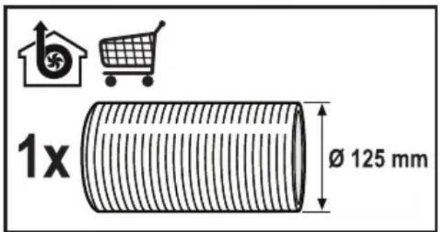
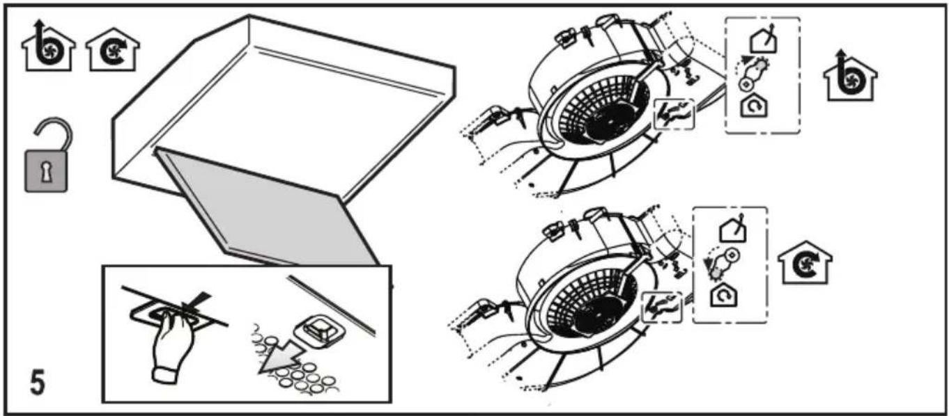
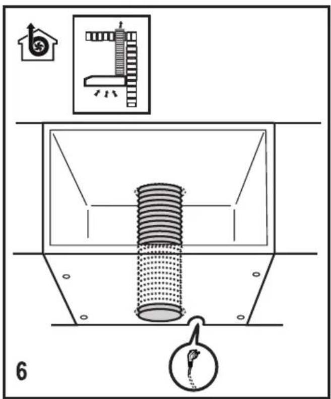
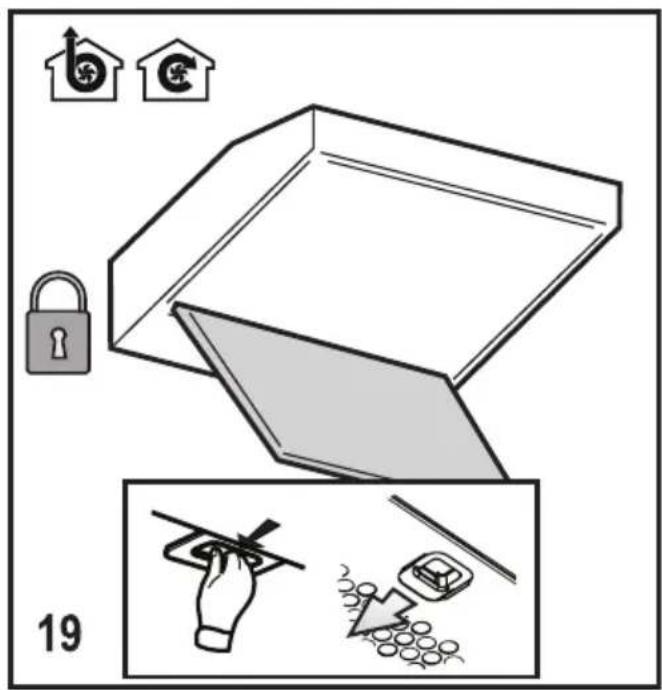
The hood is designed to be used either for
exhausting or filter version .
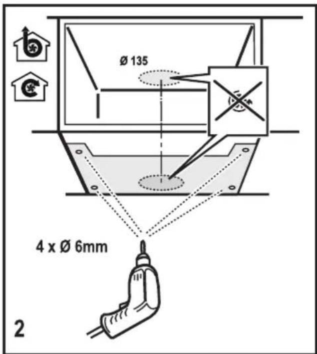
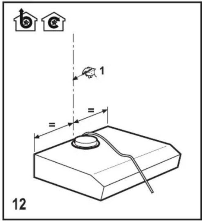
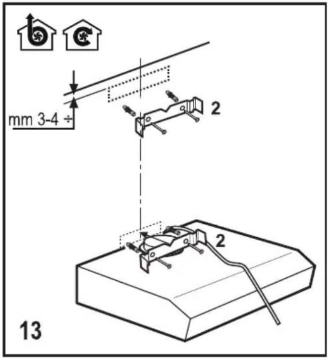
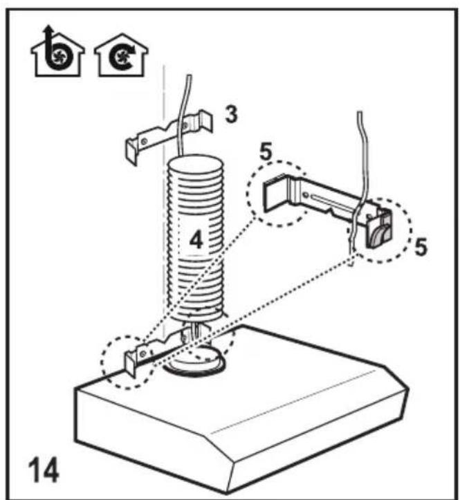
INSTALLATION
The mains power supply must correspond to the rating indicated on the plate situated inside the hood. If provided with a plug connect the hood to a socket in compliance with current regulations and positioned in an accessible area, after installation. If it not fitted with a plug (direct mains connection) or if the plug is not located in an accessible area, after installation, apply a double pole switch in accordance with standards which assures the complete disconnection of the mains under conditions relating to over-current category III in accordance with installation instructions.

Warning! Before re-connecting the hood circuit to the mains supply and checking the efficient function, always check that the mains cable is correctly assembled.
Warning! Power cable replacement must be undertaken by the authorised service assistance centre or similar qualified person.
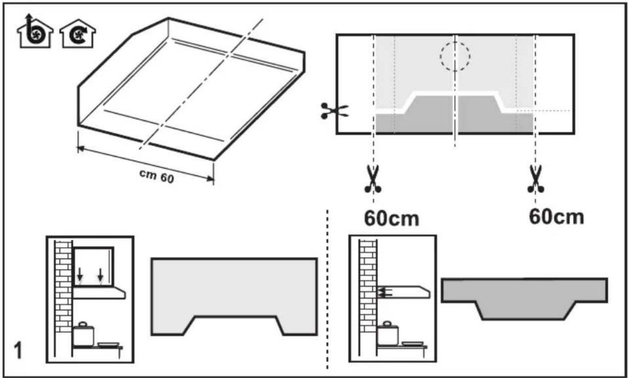
The minimum distance between the supporting surface for the cooking equipment on the hob and the lowest part of the range hood must be not less than 50cm from electric cookers and 65cm from gas or mixed cookers. If the instructions for installation for the gas hob specify a greater distance, this must be adhered to.
MAINTENANCE
ATTENTION! Before performing any maintenance operation, isolate the hood from the electrical supply by switching off at the connector and removing the connector fuse. Or if the appliance has been connected through a plug and socket, then the plug must be removed from the socket.
The cooker hood should be cleaned regularly (at least with the same frequency with which you carry out maintenance of the fat filters) internally and externally. Clean using the cloth dampened with neutral liquid detergent. Do not use abrasive products. DO NOT USE ALCOHOL!
Warning! Failure to carry out the basic cleaning recommendations of the cooker hood and replacement of the filters may cause fire risks. Therefore, we recommend observing these instructions. The manufacturer declines all responsibility for any damage to the motor or any fire damage linked to inappropriate maintenance or failure to observe the above safety recommendations.
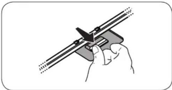
Grease filter - The grease filter must be cleaned once a month using non aggressive detergents, either by hand or in the dishwasher, which must be set to a low temperature and a short cycle. When washed in a dishwasher, the grease filter may discolour slightly, but this does not affect its filtering capacity.
natural_image
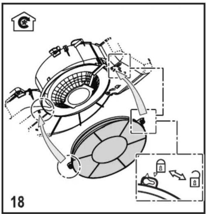
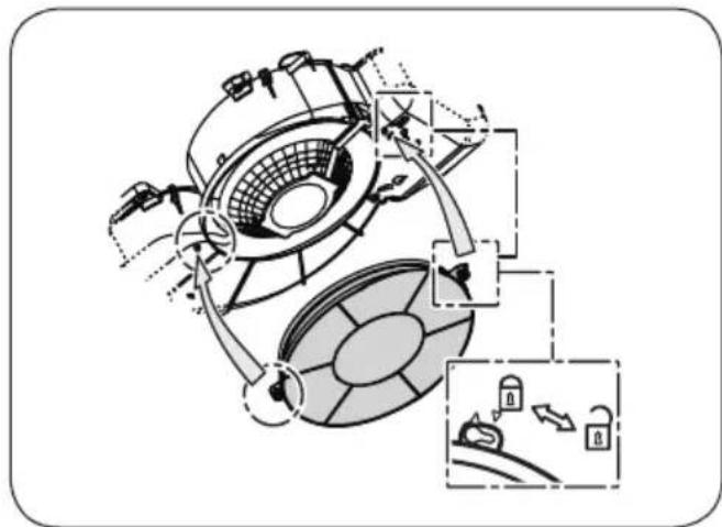
Illustration of a hand using a tool to adjust or install a mechanical component (no text or symbols visible)NON-washable activated charcoal filter
The saturation of the charcoal filter occurs after more or less prolonged use, depending on the type of cooking and the regularity of cleaning of the grease filter. In any case it is necessary to replace the cartridge at least every four mounths. The charcoal filter may NOT be washed or regenerated.
natural_image
Technical diagram of a mechanical device with internal components and directional arrows, no visible text or symbolsCONTROLS
The hood is fitted with a control panel with aspiration speed selection control and a light switch to control cooking area lights.
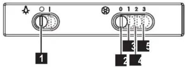
1 ON/OFF lights
2 OFF motors
3 Minimum suction power
4 Medium suction power
5 Maximum suction power
Use the high suction speed in cases of concentrated kitchen vapours. It is recommended that the cooker hood suction is switched on for 5 minutes prior to cooking and to leave in operation during cooking and for another 15 minutes approximately after terminating cooking.
LIGHTING
Disconnect the hood from the electricity.

Warning! Prior to touching the light bulbs ensure they are cooled down.
Replace the damaged lamp.
Use E14 3W max LED lamps only. For more details, check enclosed leaflet "ILCOS D" (alfanumeric position "1d").
⚠ INFORMATION DE SÉCURITÉ
natural_image
Illustration of a hand using a tool to adjust or install a mechanical component (no text or symbols visible)COMMANDES
natural_image
Illustration of a hand using a tool to adjust or install a mechanical component (no text or symbols visible)natural_image
Technical diagram of a mechanical device with internal components and a close-up inset showing lock mechanism (no text or labels)BEDIENELEMENTE
natural_image
Illustration of a hand using a tool to adjust or install a mechanical component (no text or symbols visible)NIET wasbaar koolstofffilter
BEDIENINGSELEMENTEN
natural_image
Illustration of a hand using a tool to adjust or install a mechanical component (no text or symbols visible)natural_image
Technical diagram of a mechanical device with internal components and directional arrows, no visible text or symbolsMANDOS
natural_image
Illustration of a hand using a tool to cut or adjust a mechanical component (no text or symbols visible)natural_image
Technical diagram of a mechanical device with internal components and directional arrows, no visible text or symbolsCOMANDOS
natural_image
Illustration of a hand using a cutting tool to cut a metal sheet (no text or symbols visible)natural_image
Technical diagram of a mechanical device with internal components and a close-up inset showing hand positioning (no text or labels)ΧΕΙΡΙΣΤΗΡΙΑ
natural_image
Illustration of a hand using a tool to adjust or install a mechanical component (no text or symbols visible)natural_image
Technical diagram of a mechanical device with internal components and directional arrows, no visible text or symbolsОРГАНЫ УПРАВЛЕНИЯ
natural_image
Illustration of a hand using a tool to adjust or install a mechanical component (no text or symbols visible)Yıkanamayan aktif karbon filtre
KONTROLLER
natural_image
Technical diagram of a mechanical assembly with internal components and directional arrows, no visible text or symbolsأوامر التحكم
natural_image
Illustration of a hand using a tool to cut or adjust a mechanical component (no text or symbols visible)natural_image
Illustration of a hand using a tool to adjust or install a mechanical component (no text or symbols visible)natural_image
Technical diagram of a mechanical device with internal components and directional arrows, no visible text or symbolsKOMMANDON
natural_image
Illustration of a hand using a tool to adjust or install a mechanical component (no text or symbols visible)natural_image
Technical diagram of a mechanical device with internal components and directional arrows, no visible text or symbolsKONTROLLER
natural_image
Illustration of a hand using a tool to adjust or install a mechanical component (no text or symbols visible)natural_image
Technical diagram of a mechanical device with internal components and control panel (no text or labels)OHJAIMET
natural_image
Illustration of a hand using a tool to adjust or install a mechanical component (no text or symbols visible)natural_image
Technical diagram of a mechanical device with internal components and directional arrows, no visible text or symbolsBETJENING
natural_image
Illustration of a hand using a tool to cut or adjust a mechanical component (no text or symbols visible)natural_image
Technical diagram of a mechanical device with internal components and directional arrows, no visible text or symbolsSTEROWANIE
natural_image
Illustration of a hand using a tool to cut or adjust a mechanical component (no text or symbols visible)natural_image
Technical diagram of a mechanical device with internal components and directional arrows, no visible text or symbolsKEZELŐSZERVEK
Use the correct length for the screws which are identified in the Installation Guide.
natural_image
Illustration of a hand using a tool to adjust or install a mechanical component (no text or symbols visible)Filtru cu carbon activ NEIavabil
COMENZI
natural_image
Illustration of a hand using a tool to adjust or install a mechanical component (no text or symbols visible)Aktivni karbonski filtar koji se NE može oprati.
Zasićenje karbonskog filtra se pojavljuje poslije manje-više produljene uporabe s obzirom na tip kuhinje i na urednost u čišćenju filtera za uklanjanje
natural_image
Technical diagram of a mechanical device with internal components and directional arrows, no visible text or symbolsNAREDBI
natural_image
Illustration of a hand using a tool to adjust or install a mechanical component (no text or symbols visible)OVLÁDAČE
natural_image
Illustration of a hand using a tool to adjust or install a mechanical component (no text or symbols visible)PŘÍKAZY
natural_image
Illustration of a hand using a tool to adjust or install a mechanical component (no text or symbols visible)Nepralni filter z aktivnim ogljem
natural_image
Technical diagram of a mechanical device with internal components and labeled parts (no readable text or symbols)UPRAVLJALNI GUMBI
natural_image
Illustration of a hand using a tool to cut or adjust a mechanical component (no text or symbols visible)natural_image
Technical diagram of a mechanical device with internal components and directional arrows, no visible text or symbolsKOMANDIMET
natural_image
Illustration of a hand using a tool to adjust or install a mechanical component (no text or symbols visible)natural_image
Technical diagram of a mechanical device with internal components and a close-up inset showing internal parts (no text or labels)УПРАВЛЕНИЯ
natural_image
Illustration of a hand using a tool to cut or adjust a mechanical component (no text or symbols visible)natural_image
Technical diagram of a mechanical device with internal components and directional arrows, no visible text or symbolsКОНТРОЛИ
natural_image
Illustration of a hand using a tool to adjust or install a mechanical component (no text or symbols visible)natural_image
Technical diagram of a mechanical device with internal components and labeled parts (no readable text or symbols)КОМАНДЕ
natural_image
Illustration of a hand using a tool to adjust or install a mechanical component (no text or symbols visible)MITTEPESTAV aktiivsöefilter
natural_image
Technical diagram of a mechanical device with internal components and directional arrows, no visible text or symbolsJUHIKUD
natural_image
Illustration of a hand using a tool to cut or adjust a mechanical component (no text or symbols visible)natural_image
Technical diagram of a mechanical device with internal components and a close-up inset showing lock mechanism (no text or labels)ЕЛЕМЕНТИ КЕРУВАННЯ
natural_image
Illustration of a hand using a tool to cut or adjust a mechanical component (no text or symbols visible)natural_image
Technical diagram of a mechanical device with internal components and directional arrows, no visible text or symbolsБАСКАРУ ЭЛЕМЕНТТЕРИ
natural_image
Illustration of a hand using a tool to adjust or install a mechanical component (no text or symbols visible)natural_image
Technical diagram of a mechanical device with internal components and labeled parts (no readable text or symbols)VADĪBAS ELEMENTI
natural_image
Illustration of a hand using a tool to adjust or install a mechanical component (no text or symbols visible)Neplaunamas aktyviosios anglies filtras
natural_image
Technical diagram of a mechanical device with internal components and directional arrows, no visible text or symbolsVALDYMAS
natural_image
Four icon buttons representing different consumer goods: washing machine, gear, shopping cart, and shopping cart (no text or symbols)CE

- COMANDI
- ⚠ SAFETY INFORMATION
- SAFETY INSTRUCTIONS
- ENVIRONMENT CONCERNS
- USE
- INSTALLATION
- MAINTENANCE
- NON-washable activated charcoal filter
- CONTROLS
- LIGHTING
- ⚠ INFORMATION DE SÉCURITÉ
- COMMANDES
- BEDIENELEMENTE
- NIET wasbaar koolstofffilter
- BEDIENINGSELEMENTEN
- MANDOS
- COMANDOS
- ΧΕΙΡΙΣΤΗΡΙΑ
- ОРГАНЫ УПРАВЛЕНИЯ
- Yıkanamayan aktif karbon filtre
- KONTROLLER
- KOMMANDON
- OHJAIMET
- BETJENING
- STEROWANIE
- KEZELŐSZERVEK
- Filtru cu carbon activ NEIavabil
- COMENZI
- Aktivni karbonski filtar koji se NE može oprati.
- NAREDBI
- OVLÁDAČE
- PŘÍKAZY
- Nepralni filter z aktivnim ogljem
- UPRAVLJALNI GUMBI
- KOMANDIMET
- УПРАВЛЕНИЯ
- КОНТРОЛИ
- КОМАНДЕ
- MITTEPESTAV aktiivsöefilter
- JUHIKUD
- ЕЛЕМЕНТИ КЕРУВАННЯ
- БАСКАРУ ЭЛЕМЕНТТЕРИ
- VADĪBAS ELEMENTI
- Neplaunamas aktyviosios anglies filtras
- VALDYMAS
Brand : ZANUSSI
Model : ZHC6122X
Category : Basket