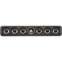
Vanishing 625RT - Speaker POLK - Free user manual and instructions
Find the device manual for free Vanishing 625RT POLK in PDF.
User questions about Vanishing 625RT POLK
0 question about this device. Answer the ones you know or ask your own.
Ask a new question about this device
Download the instructions for your Speaker in PDF format for free! Find your manual Vanishing 625RT - POLK and take your electronic device back in hand. On this page are published all the documents necessary for the use of your device. Vanishing 625RT by POLK.
USER MANUAL Vanishing 625RT POLK
- Read these instructions.
- Keep these instructions.
- Heed all warnings.
- Follow all instructions.
- Do not use this apparatus near water.
- Clean only with dry cloth.
- Do not block any ventilation openings. Install in accordance with the manufacturer's instructions.
- Do not install near any heat sources such as radiators, heat registers, stoves, or other apparatus (including amplifiers) that produce heat.
- Refer all servicing to qualified service personnel. Servicing is required when the apparatus has been damaged in any way, liquid has been spilled or objects have fallen into the apparatus, the apparatus has been exposed to rain or moisture, does not operate normally, or has been dropped.
- WARNING: To reduce the risk of fire or electric shock, this apparatus should not be exposed to rain or moisture and objects filled with liquids, such as vases, should not be placed on this apparatus.

Product Disposal—Certain international, national and/or local laws and/or regulations may apply regarding the disposal of this product. For further detailed information, please contact the retailer where you purchased this product or the Polk Audio Importer/
Distributor in your country. A listing of Polk Audio Importer/Distributors can be found on the Polk Audio website www.polkaudio.com or by contacting Polk Audio at 5601 Metro Drive, Baltimore, Maryland 21215, USA—Phone: +1 410 358-3600.
WARNING: Listen Carefully
Polk Audio loudspeakers and subwoofers are capable of playing at extremely high volume levels, which could cause serious or permanent hearing damage. Polk Audio, Inc. accepts no liability for hearing loss, bodily injury or property damage resulting from the misuse of its products.
Keep these guidelines in mind and always use your own good judgment when controlling volume:
- You should limit prolonged exposure to volumes that exceed 85 decibels(dB).
For more about safe volume levels, go to the Occupational Health and Safety Administration (OSHA) guidelines at http://www.osha.gov/dts/osta/otm/noise/standards_more.html
TAKE INVENTORY
Inside each speaker container, you should find the following:
- One in-wall loudspeaker or one set of loudspeakers for F/X ^® models only.
- Speaker cutout mounting template
- One Sheer-Grille (for each speaker)
- Port plug (265-LS, 65F/x-LS, 65-LS, 265-RT, 65F/x-RT & 65-RT only)
- One Owner's Manual
- Registration Card
Important Note: If anything is missing or damaged, or if your speaker fails to operate, notify Polk Audio Customer Support Services immediately at 800-377-7655.
INSTALLATION RECOMMENDATION FOR OPTIMUM PERFORMANCE
Important Note: Vanishing Series Loudspeakers are not magnetically shielded and should not be placed closer than 1' (30cm) from a CRT (tube) television or video monitor.
Important Note: You should have a thorough understanding of and adhere to all local building and fire codes. Also, you should be familiar with the area behind the wall or ceiling into which you plan to install your speakers. Always use wire that meets appropriate building and fire codes. (Note: Wiring is best performed by an experienced professional.)
When installing your loudspeakers, be aware of the weight of your particular model and the sturdiness of the material into which you are installing the speaker. Be aware of any concealed studs, electrical wiring or plumbing in the wall or ceiling into which you are installing the speakers.
If you doubt that you possess the necessary skills or tools, consult your Polk Audio dealer or a professional installer.
WIRE RECOMMENDATIONS
(minimum recommended)
Runs Gauge
| Lengths up to 25' 18 or 16 | |
| Lengths greater than 25' but less than 50' | 16 or 14 |
| Lengths greater than 50' but less than 75' | 14 or 12 |
| Lengths greater than 75' | 12 |
LOUDSPEAKER INSTALLATION
You will need:
• Pencil for marking the location of installation.
• Keyhole saw, utility knife or material-appropriate tool for cutting drywall or other wall material.
- Level.
- Screwdriver, preferably powered, with Phillips Head bit.
• Power drill with appropriate bit (optional, for starting wall cut).
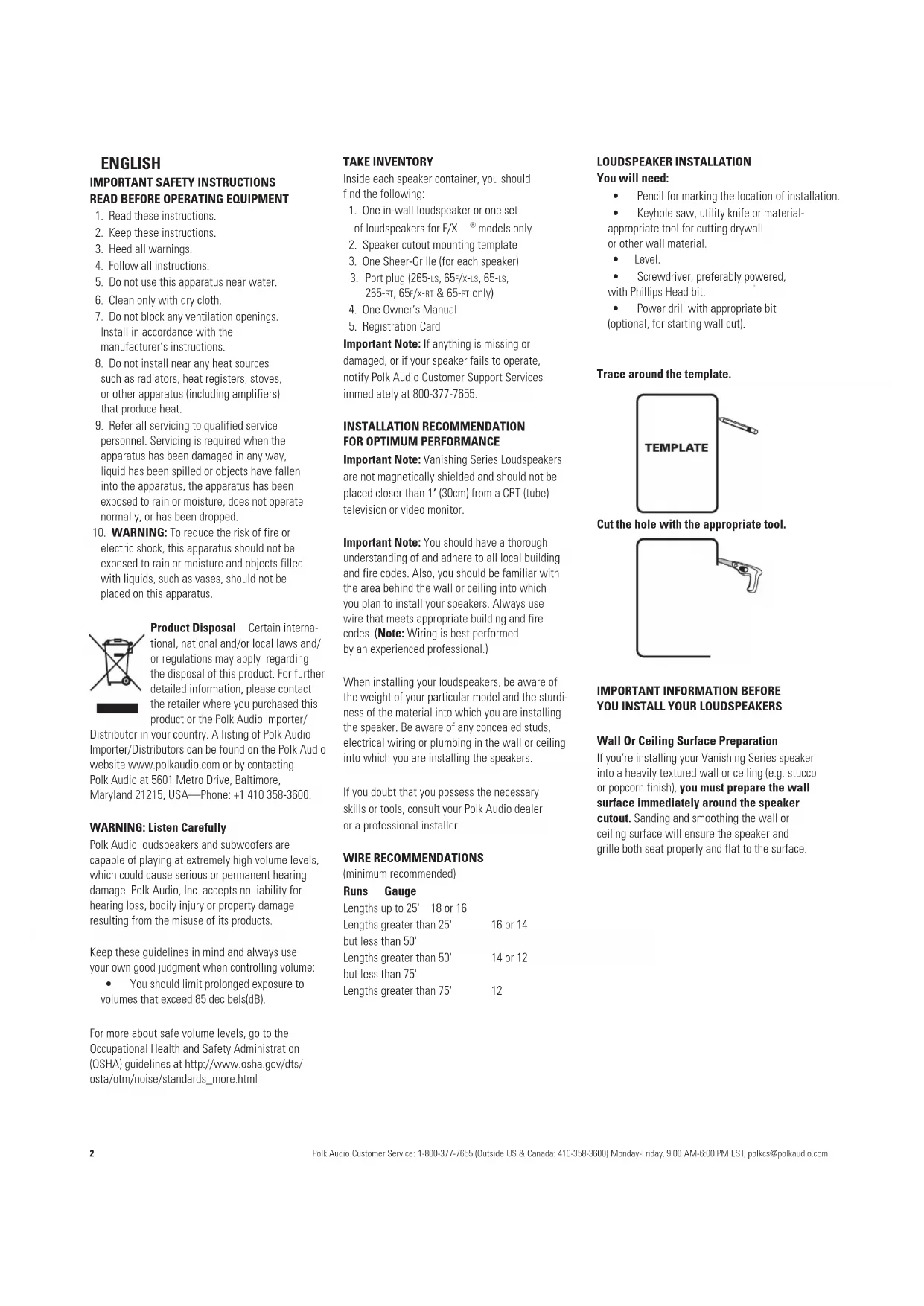
Trace around the template.

text_image
TEMPLATECut the hole with the appropriate tool.
natural_image
Simple line drawing of a bracket with a handle (no text or symbols)IMPORTANT INFORMATION BEFORE YOU INSTALL YOUR LOUDSPEAKERS
Wall Or Ceiling Surface Preparation
If you're installing your Vanishing Series speaker into a heavily textured wall or ceiling (e.g. stucco or popcorn finish), you must prepare the wall surface immediately around the speaker cutout. Sanding and smoothing the wall or ceiling surface will ensure the speaker and grille both seat properly and flat to the surface.
IMPORTANT INFORMATION SHOULD YOU CHOOSE TO PAINT YOUR GRILLES
Because of its ultra-thin profile, the Vanishing Series Sheer-Grille ^™ requires a specific painting procedure to ensure smooth, even coverage. The grille scrim and perforated grille come assembled and require no disassembly.
Paint Recommendation
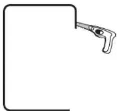
We highly recommend you use a can of spray paint matched to the wall color you want the Sheer-Grilles to blend with.
Important Note: Never use a brush or roller to paint the grilles, as this will clog the perf holes.
To paint the Sheer-Grille
- Elevate the Sheer-Grille off of a flat surface. This will ensure even coverage of the grille frame and make it easier to pick up.
Mounting Idea: Two spray can caps will raise the grille high enough.
- Hold the spray paint about 12" from the grille and at a 45° angle.
natural_image
Illustration of a hand spraying water onto a surface with an arrow indicating direction (no text or symbols)- Apply one light, thin coat, moving evenly side to side over the grille, then work your way around the perimeter of the grille to ensure you cover the grille frame.
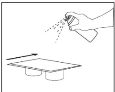
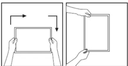
- After each application of paint, wait approximately 1 minute, rotate the grille 90°, and apply the next thin coat.
Important Note: You must rotate the grille 90°. Use your hands to define the next 90° rotation and always rotate the grille in the same direction of travel.
natural_image
Two-step diagram showing hands holding a blank rectangular frame, with arrows indicating rotation and shading (no text or symbols)- Three light, even applications should cover the grille and frame adequately. Remember to work your way around the grille frame to cover it evenly and completely.
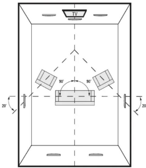
Polk Audio F/X ^® surround loudspeakers give you nearly endless placement options. But remember that where you place your surround speakers requires some careful thought, as installation requires that you cut a hole in your wall or ceiling.
text_image
TV 90° 90° 20° 20°Diagram shows speaker locations for 5.1 and 7.1 systems, when two additional in-wall speakers are installed in the rear wall.
Left/Right Orientation: F/X ^® surround loud-speakers have a left/right orientation, and each speaker is clearly marked on the serial number label on the back of the magnet for installation on either the right or left. Right and left are defined from your listening area as you face your system's center channel.
Center Channel Speaker Placement
Install the 255c-LS or 255c-HT as close as possible to ear level. If the speaker needs to be installed higher, aim the tweeter down as required.
Do not block the center channel with your TV or furniture.
Please Note: For more on speaker placement go to: www.polkaudio.com/education/article.php?id=15 or www.polkaudio.com/downloads/hthandbook.pdf
ROOM ENVIRONMENT CONTROLS

Imaging (65F/x-LS model only)
F/X Surround Loudspeakers offer switchable "Diffuse" and "Solid" imaging patterns to create the surround effect you desire.
A "Diffuse" image is defined as one which creates a "cloud" of sound; think of the effect as ambient sounds which fill the environment all around you, but are less localizable.
A "Solid" image is one which creates a more pinpoint sound; sound is more localized. The location of sounds in the sound field is more identifiable.
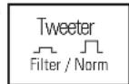
Tweeter Switch
(LS and RT models except F/X models)
Filter—If your listening room is very reflective, with smooth sheetrock walls, hardwood floors, and non-cushioned furniture, the sound will be overly "bright" and unnatural. Selecting the "Filter" setting compensates for the effect of reflectivity in a hard room. Tweeter attenuation flattens room response, without hindering higher frequency response, for warmer, more realistic sound and more accurate imaging.
Norm—If your room is not reflective, with curtains, artwork, lots of cushioned furniture and carpeting, sound will be absorbed by the room, resulting in more realistic reproduction and more accurate imaging. In this case, select the tweeter "Norm" setting.
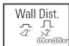
Wall Distance Switch (65F/x-RT and all LS Models except the Center Channel) In-wall loudspeakers excel when placed more than 2' (60cm) from side walls. If position limitations demand that in-wall loudspeakers be installed closer than 2' (60cm) from side walls or ceiling, the proximity of the surface can result in a response "bump" between 50 and 200Hz. This can cause in-wall speakers to sound "boomy." The "Wall Distance" switch flattens response and eliminates "boominess" without sacrificing deep bass response, for more lifelike sound.
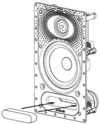
WHEN TO USE THE PROVIDED PORT PLUG
Important Note: Use the provided port plug when you are installing any of the in-wall loudspeakers listed below in an area larger than a standard open stud bay. Ensure the plug seats all the way into the port.
The port plug should be used on the following
models: 265-LS, 65F/x-LS, 65-LS, 265-RT, 65F/x-RT & 65-RT.
natural_image
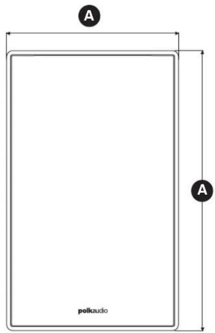
Technical line drawing of a speaker assembly with mounting bracket and drive housing (no text or symbols)DIMENSIONS
| Model | 265-LS | 265-RT | 65F/x-LS | 65F/x-RT |
| A. Overall Dimensions | 20 7/8" H x 8 7/8" W(530.2mm x 225.4mm) | 20 7/8" H x 8 7/8" W(530.2mm x 225.4mm) | 14 3/8" H x 8 7/8" W(365.1mm x 225.4mm) | 14 3/8" H x 8 7/8" W(365.1mm x 225.4mm) |
| B. Cutout Dimensions | 19 3/16" H x 7 1/4" W(487.4mm x 184.2mm) | 19 3/16" H x 7 1/4" W(487.4mm x 184.2mm) | 12 3/4" H x 7 1/4" W(323.9mm x 184.2mm) | 12 3/4" H x 7 1/4" W(323.9mm x 184.2mm) |
| C. Product Depth | 3 3/4" (95.3mm) | 3 3/4" (95.3mm) | 3 1/2" (88.9mm) | 3 1/2" (88.9mm) |
| D. Mounting Depth(using 1/2" drywall) | 3 1/4" (82.6mm) | 3 1/4" (82.6mm) | 3" (76.2mm) | 3" (76.2mm) |
DIMENSIONS
| Model | 625-RT | 65-LS | 65-RT |
| A. Overall Dimensions | 14 3/8" H x 8 7/8" W(365.1mm x 225.4mm) | 14 3/8" H x 8 7/8" W(365.1mm x 225.4mm) | 14 3/8" H x 8 7/8" W(365.1mm x 225.4mm) |
| B. Cutout Dimensions | 12 3/4" H x 7 1/4" W(323.9mm x 184.2mm) | 12 3/4" H x 7 1/4" W(323.9mm x 184.2mm) | 12 3/4" H x 7 1/4" W(323.9mm x 184.2mm) |
| C. Product Depth | 3 3/8" (85.7mm) | 3 1/2" (88.9mm) | 3 1/2" (88.9mm) |
| D. Mounting Depth(using 1/2" drywall) | 2 7/8" (73mm) | 3" (76.2mm) | 3" (76.2mm) |
DIMENSIONS (CENTER CHANNEL)
| Model | 255c-Ls | 255c-RT |
| A. Overall Dimensions | 9 5/16" H x 14 13/16" W(236.5mm x 376.2mm) | 9 5/16" H x 14 13/16" W(236.5mm x 376.2mm) |
| B. Cutout Dimensions | 7 5/8" H x 13 1/8" W(193.7mm x 333.4mm) | 7 5/8" H x 13 1/8" W(193.7mm x 333.4mm) |
| C. Product Depth | 3 3/4" (95.3mm) 3 3/4" (95.3mm) | |
| D. Mounting Depth(using 1/2" drywall) | 3 1/4" (82.6mm) | 3 1/4" (82.6mm) |
SPECIFIATIONS
For complete Vanishing Series specifications, visit www.polkaudio.com
text_image
A A polkaudio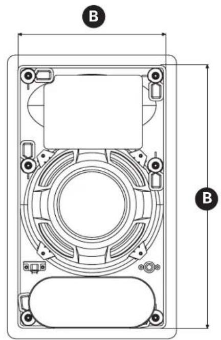
text_image
B B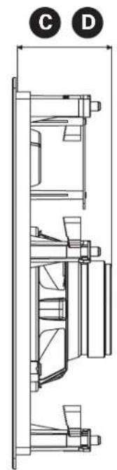
natural_image
Technical line drawing of a mechanical assembly with labeled components (C and D), no readable text or symbols present.
text_image
A A polkaudio
text_image
B B
natural_image
Technical line drawing of a mechanical assembly with no visible text or symbolsFRANÇAIS
CONSIGNES DE SÉCURITÉ IMPORTANTES À LIRE ATTENTIVEMENT AVANT D'UTILISER LE PRODUIT
natural_image
Simple line drawing of a bracket with a handle, no text or symbols presentINSTRUCTION IMPORTANTE AVANT D'INSTALLER LES HAUT-PARLEURS
Peinture: recommendation
natural_image
Illustration of a hand spraying water onto a surface with an arrow indicating direction (no text or symbols)natural_image
Illustration of two hands holding a blank tablet with arrows indicating direction (no text or symbols)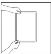
natural_image
Line drawing of a hand holding a rectangular frame (no text or symbols)natural_image
Technical line drawing of a speaker assembly with visible gears and shafts (no text or symbols)DIMENSIONS
| Modèle | 265-LS | 265-RT | 65F/x-LS | 65F/x-RT |
| A. Dimensions hors tout | 20 7/8" H x 8 7/8" W(530,2mm x 225,4mm) | 20 7/8" H x 8 7/8" W(530,2mm x 225,4mm) | 14 3/8" H x 8 7/8" W(365,1mm x 225,4mm) | 14 3/8" H x 8 7/8" W(365,1mm x 225,4mm) |
| B. Dimensions du trou | 19 3/16" H x 7 1/4" W(487,4mm x 184,2mm) | 19 3/16" H x 7 1/4" W(487,4mm x 184,2mm) | 12 3/4" H x 7 1/4" W(323,9mm x 184,2mm) | 12 3/4" H x 7 1/4" W(323,9mm x 184,2mm) |
| C. Profondeur du h.p. | 3 3/4" (95,3mm) | 3 3/4" (95,3mm) | 3 1/2" (88,9mm) | 3 1/2" (88,9mm) |
| D. Profondeur de montage(placoplâtre 1/2") | 3 1/4" (82,6mm) | 3 1/4" (82,6mm) | 3" (76,2mm) | 3" (76,2mm) |
DIMENSIONS
| Modèle | 625-RT | 65-LS | 65-RT |
| A. Dimensions hors tout | 14 3/8" H x 8 7/8" W(365,1mm x 225,4mm) | 14 3/8" H x 8 7/8" W(365,1mm x 225,4mm) | 14 3/8" H x 8 7/8" W(365,1mm x 225,4mm) |
| B. Dimensions du trou | 12 3/4" H x 7 1/4" W(323,9mm x 184,2mm) | 12 3/4" H x 7 1/4" W(323,9mm x 184,2mm) | 12 3/4" H x 7 1/4" W(323,9mm x 184,2mm) |
| C. Profondeur du h.p. | 3 3/8" (85,7mm) | 3 1/2" (88,9mm) | 3 1/2" (88,9mm) |
| D. Profondeur de montage(placoplâtre 1/2") | 2 7/8" (73mm) | 3" (76,2mm) | 3" (76,2mm) |
DIMENSIONS (CANAL CENTRAL)
| Modèle | 255c-Ls | 255c-RT |
| A. Dimensions hors tout | 9 5/16" H x 14 13/16" W(236,5mm x 376,2mm) | 9 5/16" H x 14 13/16" W(236,5mm x 376,2mm) |
| B. Dimensions du trou | 7 5/8" H x 13 1/8" W(193,7mm x 333,4mm) | 7 5/8" H x 13 1/8" W(193,7mm x 333,4mm) |
| C. Profondeur du h.p. | 3 3/4" (95,3mm) 3 3/4" (95,3mm) | |
| D. Profondeur de montage(placoplâtre 1/2") | 3 1/4" (82,6mm) | 3 1/4" (82,6mm) |
FICHE TECHNIQUE
natural_image
Technical line drawing of a mechanical assembly with labeled components (C and D), no readable text or symbols present.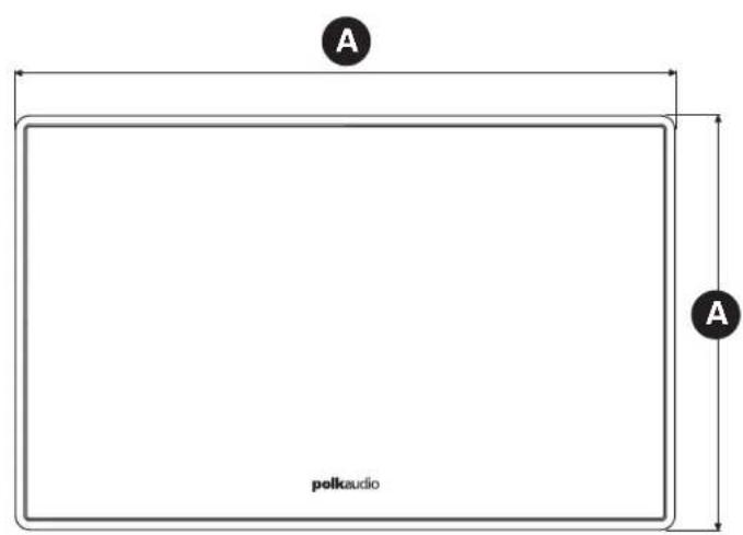
text_image
A A polkaudio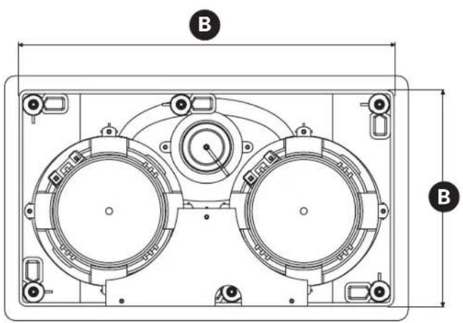
text_image
B B
natural_image
Technical line drawing of a mechanical assembly with no visible text or symbolsnatural_image
Simple line drawing of a bracket with a handle and eye symbol (no text or labels)natural_image
Illustration of a hand spraying spray onto a surface with an arrow indicating motion (no text or symbols)natural_image
Illustration of two hands holding a blank rectangular object with arrows indicating rotation or movement (no text or symbols)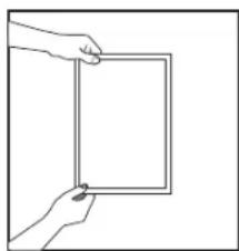
natural_image
Line drawing of a hand holding a blank rectangular frame (no text or symbols)natural_image
Technical line drawing of a speaker assembly with concentric circles and mounting holes (no text or symbols)| DIMENSIONES | ||||
| Modelo | 265-LS | 265-RT | 65F/x-LS | 65F/x-RT |
| A. Dimensiones generales | 20 7/8 plg. H x 8 7/8 plg. W (530.2mm x 225.4mm) | 20 7/8 plg. H x 8 7/8 plg. W (530.2mm x 225.4mm) | 14 3/8 plg. H x 8 7/8 plg. W (365.1mm x 225.4mm) | 14 3/8 plg. H x 8 7/8 plg. W (365.1mm x 225.4mm) |
| B. Dimensiones de la abertura | 19 3/16 plg. H x 7 1/4 plg. W (487.4mm x 184.2mm) | 19 3/16 plg. H x 7 1/4 plg. W (487.4mm x 184.2mm) | 12 3/4 plg. H x 7 1/4 plg. W (323.9mm x 184.2mm) | 12 3/4 plg. H x 7 1/4 plg. W (323.9mm x 184.2mm) |
| C. Fondo del producto | 3 3/4 plg. (95.3mm) | 3 3/4 plg. (95.3mm) | 3 1/2 plg. (88.9mm) | 3 1/2 plg. (88.9mm) |
| D. Fondo de montaje (en pared de plancha de yeso de 1/2 plg.) | 3 1/4 plg. (82.6mm) | 3 1/4 plg. (82.6mm) | 3 plg. (76.2mm) | 3 plg. (76.2mm) |
| DIMENSIONES | |||
| Modelo | 625-RT | 65-LS | 65-RT |
| A. Dimensiones generales | 14 3/8 plg. H x 8 7/8 plg. W (365.1mm x 225.4mm) | 14 3/8 plg. H x 8 7/8 plg. W (365.1mm x 225.4mm) | 14 3/8 plg. H x 8 7/8 plg. W (365.1mm x 225.4mm) |
| B. Dimensiones de la abertura | 12 3/4 plg. H x 7 1/4 plg. W (323.9mm x 184.2mm) | 12 3/4 plg. H x 7 1/4 plg. W (323.9mm x 184.2mm) | 12 3/4 plg. H x 7 1/4 plg. W (323.9mm x 184.2mm) |
| C. Fondo del producto | 3 3/8 plg. (85.7mm) | 3 1/2 plg. (88.9mm) | 3 1/2 plg. (88.9mm) |
| D. Fondo de montaje (en pared de plancha de yeso de 1/2 plg.) | 2 7/8 plg. (73mm) | 3 plg. (76.2mm) | 3 plg. (76.2mm) |
natural_image
Technical line drawing of a mechanical assembly with labeled components (C and D), no readable text or symbols present.
text_image
A A polkaudio
text_image
B B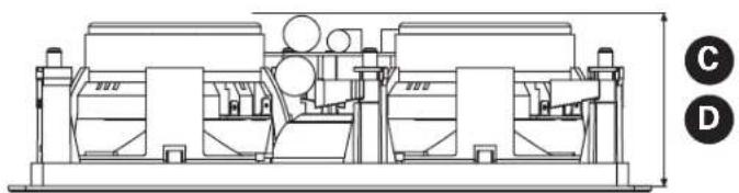
natural_image
Technical line drawing of a mechanical assembly with no visible text or symbolsLimited Lifetime Warranty for Polk Audio-Branded In-Wall and In-Ceiling Speakers
Important Note: This lifetime warranty applies only to in-wall and in-ceiling loudspeakers, and passive CSW subwoofers sold after September 9, 2009.
Polk Audio, Inc., ("Polk") warrants to the original retail purchaser that Polk Audio branded in-wall and in-ceiling speakers, including passive CSW series subwoofers (collectively "product"), will be free from defects in materials and workmanship for the life of the product, under normal use and conditions. Should this product prove to be defective in material or workmanship, Polk will, at its option, (a) repair the product, or (b) replace the product. If the product model is no longer available and cannot be repaired effectively, or replaced with an identical model, Polk may, at its sole and absolute option, replace the unit with a current model of equal or greater value.
To obtain warranty service, you may refer to the instructions in your owner's manual or visit the Polk Audio website at www.polkaudio.com. You may also contact Polk Audio Customer Service at 1-800-377-7655 for instructions on where to send the product. You will be required to provide an original receipt or bill of sale, identifying you as the original purchaser and identifying the purchase made through an authorized Polk retailer. You will need to ship the product, prepaid and insured, together with the proof of purchase to Polk Audio, Inc. 1 Viper Way, Vista, CA 92081. Risk of loss or damage in transit shall be borne by the purchaser. Freight collect shipments will be refused.
This warranty is non-transferable and does not apply to any product that has been modified or used in a manner contrary to its intended purpose, and does not cover damage to the product caused by installation or removal of the product. If modification(s) to a mounting surface are made to product(s) that have been substituted under warranty, Polk assumes no responsibility or liability for any modification made to the mounting surface or otherwise. This limited warranty is void if the product has an altered or missing serial number, or if the product was purchased from someone other than an authorized dealer. This limited warranty is void if the product has been damaged by accident or unreasonable use, neglect, improper service or other causes not arising out of defects in material or construction. Product(s) which are found to be damaged by abuse resulting in thermally damaged voice coils are not covered by this warranty but may be replaced at the sole and absolute discretion of Polk. This warranty terminates if you sell or otherwise transfer the product to another party. This limited warranty does not cover cosmetic damage, paint damage, damage to other components, parts or premises, or any consequential damages which may result for any reason. This limited warranty does not cover labor costs for the removal and/or reinstallation of the product.
THIS WARRANTY GIVES YOU SPECIFIC LEGAL RIGHTS AND YOU MAY HAVE OTHER RIGHTS THAT VARY FROM STATE TO STATE. ALL WARRANTIES, INCLUDING BUT NOT LIMITED TO EXPRESS WARRANTY, IMPLIED WARRANTIES OF MERCHANTABILITY AND FITNESS FOR A PARTICULAR PURPOSE ARE EXPRESSLY EXCLUDED AND DISCLAIMED TO THE MAXIMUM EXTENT ALLOWED BY LAW, AND POLK NEITHER ASSUMES NOR AUTHORIZES ANY PERSON TO ASSUME FOR IT ANY LIABILITY IN CONNECTION WITH THE SALE OF THE PRODUCT. POLK HAS ABSOLUTELY NO LIABILITY FOR ANY ACTS OF THIRD PARTIES. SOME STATES DO NOT ALLOW THE EXCLUSION OF CERTAIN IMPLIED WARRANTIES, OR CONDITIONS ON AN IMPLIED WARRANTY, SO THE ABOVE LIMITATION MAY NOT APPLY TO YOU. POLK DOES NOT ACCEPT LIABILITY FOR SPECIAL, INDIRECT, INCIDENTAL, PUNITIVE OR CONSEQUENTIAL DAMAGES, LOST PROFITS, LOST SAVINGS OR DAMAGES RESULTING FROM IMPROPER USE, OR THE INABILITY TO USE THE PRODUCT. THE MAXIMUM LIABILITY FOR WHICH POLK MAY BE RESPONSIBLE SHALL NOT EXCEED THE PURCHASE PRICE OF THE PRODUCT. SOME STATES DO NOT ALLOW THE EXCLUSION OR LIMITATION OF INCIDENTAL OR CONSEQUENTIAL DAMAGES, SO THE ABOVE LIMITATION OR EXCLUSIONS MAY NOT APPLY TO YOU.
the speaker specialists®
5601 Metro Drive
Baltimore, Maryland 21215
800-377-7655 (outside usA & CANADA: 410-358-3600)
www.polkaudio.com