
BDWM1000 - Workbench BLACK & DECKER - Free user manual and instructions
Find the device manual for free BDWM1000 BLACK & DECKER in PDF.

User questions about BDWM1000 BLACK & DECKER
0 question about this device. Answer the ones you know or ask your own.
Ask a new question about this device
Download the instructions for your Workbench in PDF format for free! Find your manual BDWM1000 - BLACK & DECKER and take your electronic device back in hand. On this page are published all the documents necessary for the use of your device. BDWM1000 by BLACK & DECKER.
USER MANUAL BDWM1000 BLACK & DECKER
natural_image
Technical line drawing of a mechanical device with visible internal components and mounting feet (no text or symbols)THANK YOU FOR CHOOSING BLACK & DECKER! GO TO WWW.BLACKANDDECKER.COM/NEWOWNER TO REGISTER YOUR NEW PRODUCT.
BEFORE RETURNING THIS PRODUCT FOR ANY REASON PLEASE CALL 1-800-544-6986
BEFORE YOU CALL, HAVE THE CATALOG No. AND DATE CODE AVAILABLE. IN MOST CASES, A BLACK & DECKER REPRESENTATIVE CAN RESOLVE THE PROBLEM OVER THE PHONE. IF YOU HAVE A SUGGESTION OR COMMENT, GIVE US A CALL. YOUR FEEDBACK IS VITAL TO BLACK & DECKER.
SAVE THIS MANUAL FOR FUTURE REFERENCE.
VEA EL ESPAÑOL EN LA CONTRAPORTADA.
IMPORTANT SAFETY INSTRUCTIONS
- Do not load with more than 400 lbs. (181kg). Do not leave heavy loads on work surface for extended periods of time.
- Do not apply an unbalanced load which could cause the workbench to tip over.
- Do not use the work center as a stepladder or standing platform. Do not use the lower platform as a step.
- Do not store workbench outdoors or in a damp location.
- Avoid applying excessive force when clamping with the supplied clamps.
- Be sure that the legs are fully open and the center support is in position and locked before use.
- When using a power tool with the workbench, follow the safety instructions in the tool's instruction manual.
- Do not mount or clamp power tools to any surface.
- Always wear safety glasses when operating power tools.
- Cutting or drilling into work surface may weaken supports, damaging tool or workbench.
- Caution required when using high temperature tools (heat guns, torch, solder iron, etc.). May damage work surface and reduce clamping capability.
- Do not store flammable liquids on the workbench.
SAFETY GUIDELINES - DEFINITIONS
It is important for you to read and understand this manual. The information it contains relates to protecting YOUR SAFETY and PREVENTING PROBLEMS. The symbols below are used to help you recognize this information.
⚠️ DANGER: Indicates an imminently hazardous situation which, if not avoided, will result in death or serious injury.
⚠ WARNING: Indicates a potentially hazardous situation which, if not avoided, could result in death or serious injury.
⚠️ CAUTION: Indicates a potentially hazardous situation which, if not avoided, may result in minor or moderate injury.
CAUTION: Used without the safety alert symbol indicates a potentially hazardous situation which, if not avoided, may result in property damage.
SAVE THESE INSTRUCTIONS FOR FUTURE USE
OPERATION
OPENING THE WORKBENCH
The BDWM1000 is packaged completely folded in the carton.
To open:
-
Place the workbench flat on the floor.
-
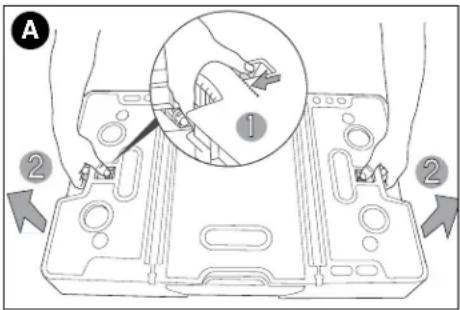
Grasp the openings on both sides of the table top and pull out on the release latches as shown in figure A.
⚠️CAUTION: Do not pull the legs out when the workbench is in a closed position.
- With the release latches pulled in, lift the table top. The four legs will drop down and lock into place and the side supports will lift up. (figure B)
text_image
A ① ② ②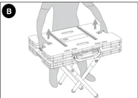
natural_image
Illustration of a person using a folding chair to lift a tray, with arrows indicating movement (no text or symbols)2
-
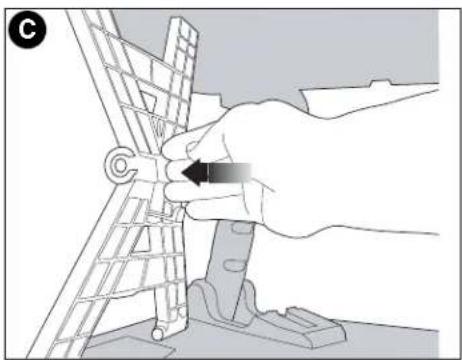
To lock the side supports, push out from the inside until the support locks into position (figure C.) CAUTION: Risk of Unsafe Operation. Make sure all four legs and both side supports are locked in place.
-
After locking the side supports in place, lift the center support section by the carrying handle until you hear it "click" into place as shown in figure D.
-
When the center support section is properly locked in position, the LOCK button shown in figure E will be visible. ⚠️ CAUTION: Risk of Unsafe Operation. Make sure the center support section is locked in place.
CLOSING THE WORKBENCH
- Fold the center support section down and push in on the side supports to unlock them. (figure F)
natural_image
Hand operating a mechanical tool with a circular component, no visible text or symbols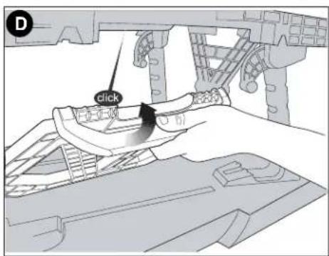
text_image
D click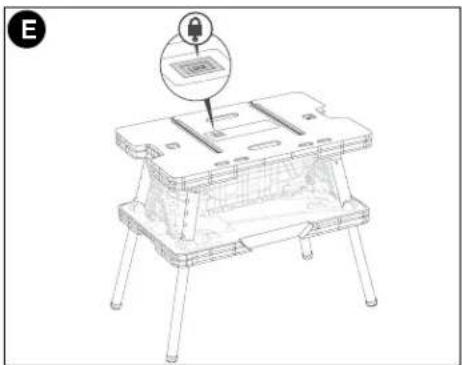
natural_image
Line drawing of a small mechanical device with a lock icon and mounting base (no text or symbols)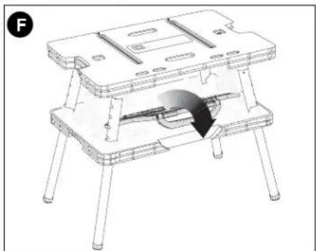
natural_image
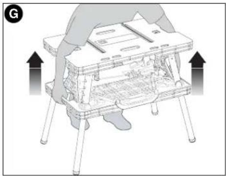
Technical line drawing of a mechanical table with legs and supports, showing internal components and a curved arrow indicating motion (no text or symbols)- Reach through the openings in the table top and grasp the lower section of the bench. Pull up on the lower section to begin collapsing the legs. (figure G)
natural_image
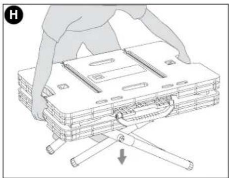
Diagram of a hand operating a small mechanical device with arrows indicating motion (no text or symbols present)- Lower the unit to the ground as shown in figure H.
natural_image
Illustration of a person assembling a multi-tiered laptop case with a hand operating the frame (no text or symbols)- Once the unit is flat on the ground, press down on the table top to place the unit into its fully closed position as shown in figure I.
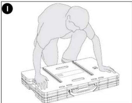
natural_image
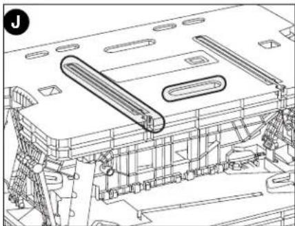
Line drawing of a person bending forward on a wooden table with a tray (no text or symbols)ADJUSTABLE CLAMPS
The two adjustable clamps can be used in both a vertical and horizontal mode. The long channels in the table top allow the clamps to be anchored in a stationary horizontal position. The shorter slots in the table top allow for the clamps to be used in a vertical position. (figure J). J1 through J6 illustrate how to use the clamps in both horizontal and vertical modes.
J1 - To expand the opening of the clamp jaws, press in on the release lever and move the jaw as shown. The jaw that is attached to the handle can also be moved in the same manner or by squeezing and releasing the front handle.
J2 - Line up the round post on the end of the clamp bar with the mating openings on both sides of the main slot in the tabletop as shown.
J3 - To lock the clamp in a horizontal position, squeeze the front handle and line up the round protruding tabs with the mating openings in the tabletop (behind the openings mentioned in J2 above).
J4 - With the clamp in a fully horizontal position, release the front handle to lock the clamp in place. (To remove the clamp, squeeze the handle and lift up.)
J5 - Depress the release lever and move the front jaw into position against the material to be clamped. Squeeze the front handle to apply pressure.
J6 - To clamp vertically, insert the clamp through the slot in the tabletop as shown.
natural_image
Technical line drawing of a mechanical assembly with no visible text or symbols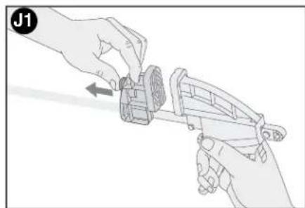
natural_image
Illustration of two hands assembling a mechanical component (no text or symbols visible)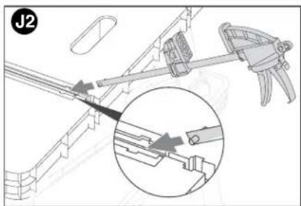
natural_image
Technical diagram of a mechanical assembly with a magnified inset showing internal components (no text or symbols)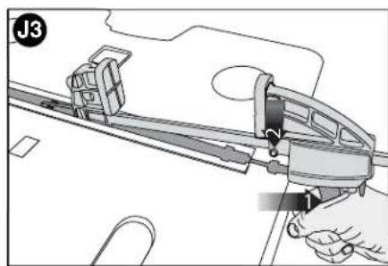
text_image
J3 2 1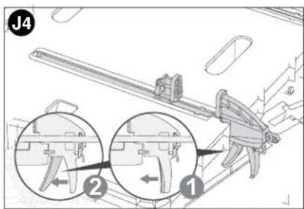
text_image
J4 1 2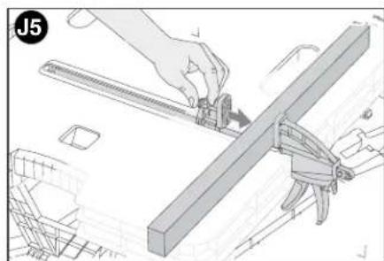
natural_image
Technical illustration of a hand using a tool to cut or adjust a metal bracket (no text or symbols visible)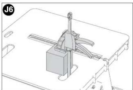
natural_image
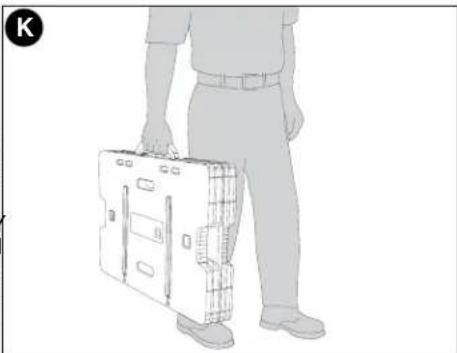
Technical line drawing of a mechanical assembly with no visible text or symbolsTRANSPORTING
- Carry the unit by the convenient carrying handle as shown in figure K.
Maintenance
Use only mild soap and damp cloth to clean the tool. Never let any liquid get inside the tool; never immerse any part of the tool into a liquid.
IMPORTANT: To assure product SAFETY and RELIABILITY, repairs, maintenance and adjustment should be performed by authorized service centers or other qualified service personnel, always using identical replacement parts.
natural_image
Illustration of a person holding a briefcase, standing with no visible text or symbolsAccessories
Recommended accessories for use with your tool are available from your local dealer or authorized service center. If you need assistance regarding accessories, please call: 1-800-544-6986.
⚠ WARNING: The use of any accessory not recommended for use with this tool could be hazardous.
Service Information
All Black & Decker Service Centers are staffed with trained personnel to provide customers with efficient and reliable power tool service. Whether you need technical advice, repair, or genuine factory replacement parts, contact the Black & Decker location nearest you. To find your local service location, refer to the yellow page directory under "Tools—Electric" or call: 1-800-544-6986 or visit www.blackanddecker.com
Full Two-Year Home Use Warranty
Black & Decker (U.S.) Inc. warrants this product for two years against any defects in material or workmanship. The defective product will be replaced or repaired at no charge in either of two ways.
The first, which will result in exchanges only, is to return the product to the retailer from whom it was purchased (provided that the store is a participating retailer). Returns should be made within the time period of the retailer's policy for exchanges (usually 30 to 90 days after the sale). Proof of purchase may be required. Please check with the retailer for their specific return policy regarding returns that are beyond the time set for exchanges.
The second option is to take or send the product (prepaid) to a Black & Decker owned or authorized Service Center for repair or replacement at our option. Proof of purchase may be required. Black & Decker owned and authorized Service Centers are listed under "Tools-Electric" in the yellow pages of the phone directory and on our website www.blackanddecker.com.
This warranty does not apply to accessories. This warranty gives you specific legal rights and you may have other rights which vary from state to state or province to province. Should you have any questions, contact the manager of your nearest Black & Decker Service Center. This product is not intended for commercial use.
FREE WARNING LABEL REPLACEMENT: If your warning labels become illegible or are missing, call 1-800-544-6986 for a free replacement.
Patents Pending
Imported by:
Black & Decker (U.S.) Inc.,
701 E. Joppa Rd.
Towson, MD 21286 U.S.A.
See 'Tools-Electric'
- Yellow Pages -
for Service & Sales


BLACK&DECKER®
ÉTABL PORTATIFF AVEC SERRE-JOINTSS
GUIDE D'UTILISATION
natural_image
Technical line drawing of a mechanical device with internal components and mounting feet (no text or symbols)MERCI D'AVOIR CHOISI BLACK & DECKER!
VISITEZ
WWW.BLACKANDDECKER.COM/PRODUCTREGISTRATION
POUR ENREGISTRER VOTRE NOUVEAU PRODUIT.
AVANT DE RETOURNER CE PRODUIT POUR QUELQUE RAISON QUE CE SOIT, COMPOSER LE
1-800-544-6986
AVANT D'APPELER, AYEZ EN MAIN LE N° DE CATALOGUE ET LE CODE DE DATE. DANS LA PLUPART
DES CAS, UN REPRÉSENTANT DE BLACK & DECKER PEUT RÉSOUDRE LE PROBLÈME PAR
TÉLÉPHONE. SI VOUS AVEZ UNE SUGGESTION OU UN COMMENTAIRE, APPELEZ-NOUS. VOS
IMPRESSIONS SONT CRUCIALES POUR BLACK & DECKER.
CONSERVER CE MANUEL POUR UN USAGE ULTÉRIEUR.
DIRECTIVES DE SÉCURITÉ IMPORTANTES
natural_image
Illustration of a person using a folding table with arrows indicating movement (no text or symbols)natural_image
Hand operating a mechanical component with a spring-like tool (no text or symbols visible)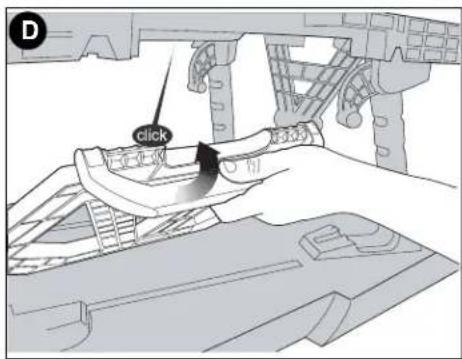
text_image
D click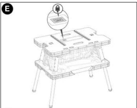
natural_image
Line drawing of a small wooden table with four legs and a small inset showing a labeled component (no text or symbols present)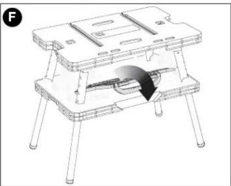
natural_image
Technical line drawing of a mechanical device with a highlighted component (no text or symbols)natural_image
Diagram of a robotic device with hands operating a platform, showing structural components and directional arrows (no text or symbols)natural_image
Illustration of a person assembling a folding table with a directional arrow indicating movement (no text or symbols)natural_image
Line drawing of a person bending over a rectangular object on a base (no text or symbols)natural_image
Technical line drawing of a mechanical assembly with no visible text or symbols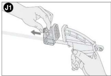
natural_image
Illustration of two hands assembling a mechanical component, no text or symbols present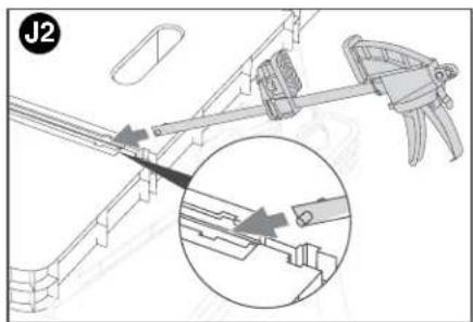
text_image
J2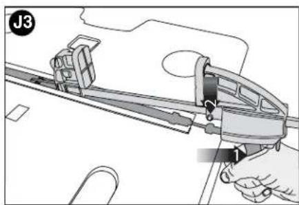
text_image
J3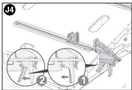
text_image
J4 ② ①
natural_image
Technical line drawing of a mechanical assembly with a hand operating a tool (no text or symbols visible)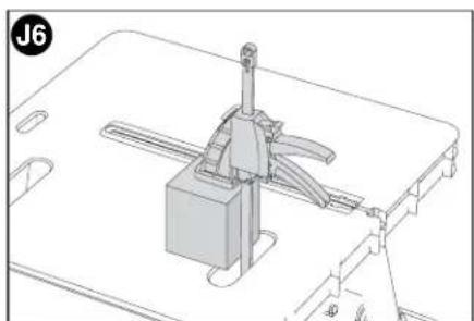
natural_image
Technical line drawing of a mechanical assembly with no visible text or symbolsTRANSPORT
natural_image
Line drawing of a person holding a briefcase, viewed from behind (no text or symbols)ACCESSOIRES
natural_image
Technical line drawing of a mechanical assembly with four legs and internal components (no text or symbols)natural_image
Illustration of a person using a folding chair to lift a seat, with arrows indicating movement (no text or symbols present)natural_image
Hand operating a mechanical component with a black arrow indicating rotation (no text or symbols present)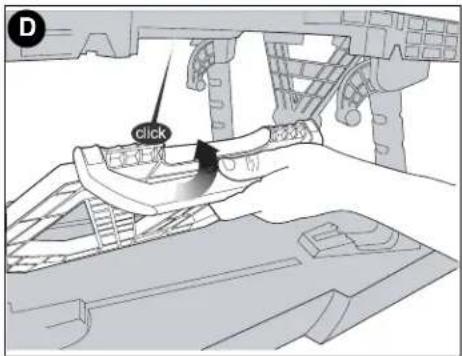
text_image
D click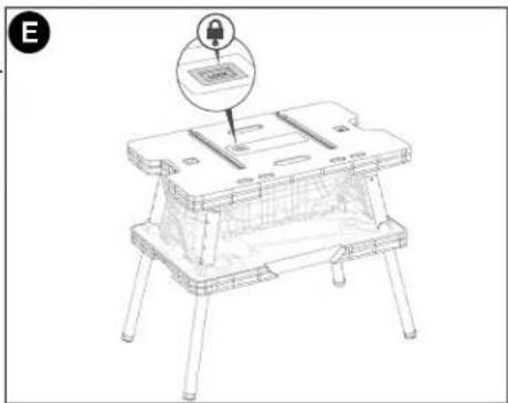
natural_image
Line drawing of a small wooden table with four legs and a lock icon above it (no text or symbols)
natural_image
Technical line drawing of a wooden table with legs and supports, showing internal components and a curved arrow indicating rotation (no text or symbols)natural_image
Diagram of a hand operating a small mechanical device with arrows indicating movement or force direction (no text or symbols present)natural_image
Line drawing of a person assembling a multi-panel table frame with a directional arrow (no text or symbols)natural_image
Line drawing of a person bending forward on a wooden table with a tray (no text or symbols)ABRAZADERAS AJUSTABLES
natural_image
Technical line drawing of a mechanical assembly with no visible text or symbols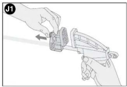
natural_image
Illustration of hands using a tool to adjust or install a mechanical component (no text or symbols visible)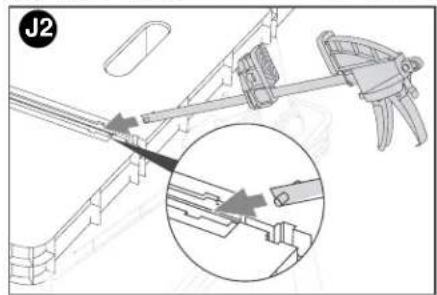
text_image
J2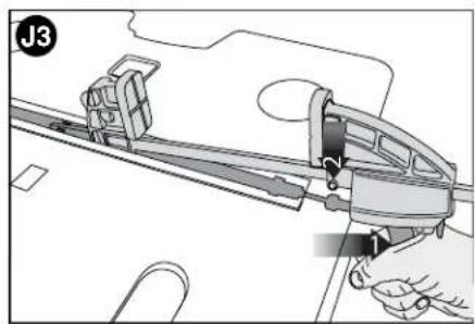
text_image
J3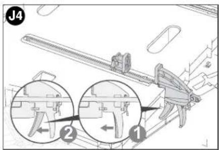
text_image
J4 ① ②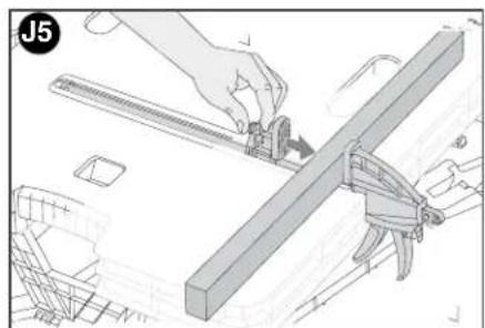
natural_image
Technical illustration of a hand operating a tool on a mechanical bracket (no text or symbols visible)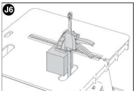
natural_image
Technical line drawing of a mechanical assembly with no visible text or symbolsTRANSPORTE
natural_image
Side profile illustration of a person holding a briefcase (no text or symbols visible)ACCESORIOS
Col. Industrial Bravo
GUADALAJARA, JAL
Av. La Paz #1779
(33) 3825 6978
Col. Americana Sector Juarez
MEXICO, D.F.
Local D, Col. Obrera
MERIDA, YUC
Calle 63 #459-A
(999) 928 5038
Col. Centro
