
DWX725 - Workbench DEWALT - Free user manual and instructions
Find the device manual for free DWX725 DEWALT in PDF.
| Product Type | Work Stand |
| Brand | DeWalt |
| Model | DWX725 |
| Maximum Load Capacity | 453.6 kg (1000 lb) on the central rail |
| Usage | On flat, stable surface, ideal for miter saws and other tools |
| Material | Heavy Duty Steel |
| Foldable Legs | Yes, with pin locking |
| Carrying Handle | Integrated |
| Transport Lock | Allows coupling two stands for transport |
| V-Grooves for Pipes | Yes, on each side |
| Installation of a Protective Wood Piece | Possible in the top groove of the rail |
| Lockable Positioning Clip | Yes (for accessory DW7231) |
| Compatible Accessories | DW7231 (miter saw bracket), DW7026 (carrying strap), DWS5026 (TrackSaw bracket) |
| Wall Storage | Possible via V-groove and screws |
| Warranty | 3 years (material/workmanship defects), 1 year free service, 90 days money-back |
| Safety Standards | ANSI Z87.1 eye protection required; do not climb or sit; do not exceed load; use on stable ground |
| Maintenance | Use only identical replacement parts; repairs by authorized center |
| Country of Manufacture | United States (Baltimore, MD) |
Frequently Asked Questions - DWX725 DEWALT
User questions about DWX725 DEWALT
0 question about this device. Answer the ones you know or ask your own.
Ask a new question about this device
Download the instructions for your Workbench in PDF format for free! Find your manual DWX725 - DEWALT and take your electronic device back in hand. On this page are published all the documents necessary for the use of your device. DWX725 by DEWALT.
USER MANUAL DWX725 DEWALT
If you have questions or comments, contact us.
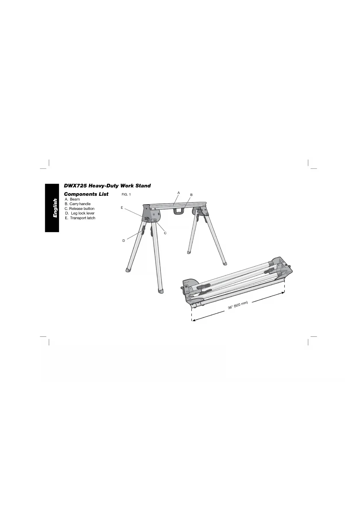
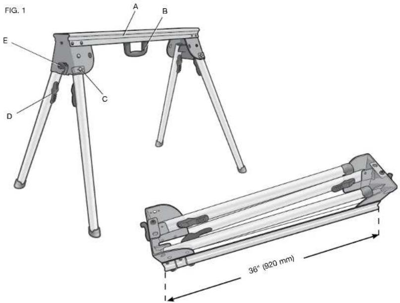
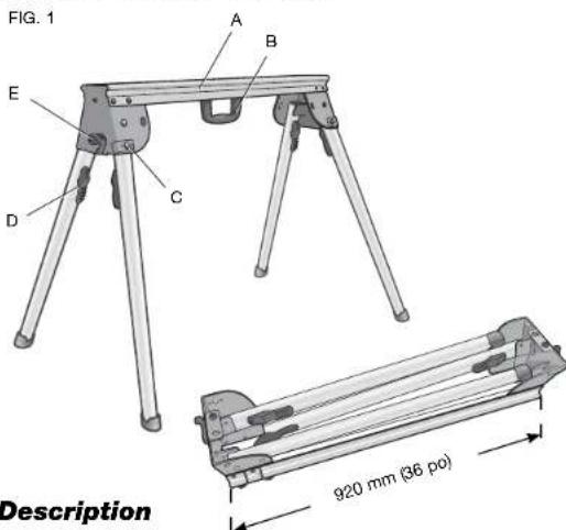
A. Beam
B. Carry handle
C. Release button
D. Leg lock lever
E. Transport latch
English
Definitions: Safety Guidelines
The definitions below describe the level of severity for each signal word. Please read the manual and pay attention to these symbols.
ADANGER: Indicates an imminently hazardous situation which, if not avoided, will result in death or serious injury.
AWARNING: Indicates a potentially hazardous situation which, if not avoided, could result in death or serious injury.
ACCAUTION: Indicates a potentially hazardous situation which, if not avoided, may result in minor or moderate injury.
NOTICE: Indicates a practice not related to personal injury which, if not avoided, may result in property damage.
IF YOU HAVE ANY QUESTIONS OR COMMENTS ABOUT THIS OR ANY DEWALT TOOL, CALL US TOLL FREE AT: 1-800-4-DEWALT (1-800-433-9258)
WARNING: For your own safety, read the work stand instruction manual before using any accessory. Failure to heed these warnings may result in personal injury and serious damage to the work stand and the accessory. When servicing this tool, use only identical replacement parts.
General Safety Instructions for Work Stand
WARNING: To reduce the risk of personal injury:
-
ALWAYS use eye protection. All users and bystanders must wear eye protection that conforms to ANSI Z87.1.
-
ALWAYS check the stability of the miter saw stand and the miter saw attached to it before putting the stand or the saw into use
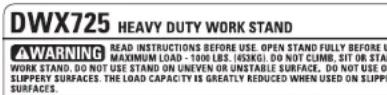
DO NOT exceed the weight this stand can hold. The main center beam of the work stand is designed to support 1000 lbs. (453.6 kg.) safely in a work environment. It is unsafe to climb, sit or stand on the stand.
DO NOT modify or use stand for operations for which it is unintended. - DO NOT use the stand on uneven surfaces. The stand is designed to be used on a flat, stable surface.
- DO NOT use on a slippery surface. The stand load capacity is greatly reduced when used on slippery surfaces.
Components (Fig. 1)
WARNING: Never modify the stand or any part of it. Damage or personal injury could result.
Refer to Figure 1 for Components List.
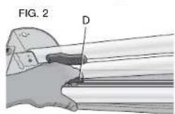
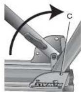
Preparation (Fig. 2)
- Place the work stand on the ground with the folded legs facing up.
English
- Depress the leg lock lever (D) or release button (C) and pull leg up until the locking pin clicks into place. Repeat on each leg.
- Lift the stand by the center beam and place it in an upright position. The stand should be stable and should not rock.
NOTE: Ensure all locking pins are engaged and the legs are locked in place.

ASSEMBLY
Transport Latch (Fig. 3)
The transport latch (E) was designed to aid in carrying two work stands at the same time by lashing two work stands together for transport.
- Place one stand on the ground with the beam (A) facing down. Place the second stand onto the first stand with the beam facing up.
NOTE: Rotate stands to ensure locator feet (F) and holes (G) align to connect stands.
- Rotate the transport latches (E) clockwise simultaneously until they latch together. Repeat on other side. Ensure the two work stands are mated properly, as shown.
- To release the transport latch:
a. Place the stands on the ground with one beam facing down.
b. Apply pressure to the tip of each transport latch hook until they move in a counterclockwise direction. Once the tips are forced past each other the latches will snap open.
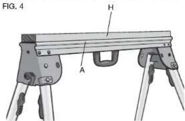
Mounting A Sacrificial Wood Surface (Fig. 4)
The DWX725 work stand allows a 2 × 4 to be mounted in the top channel of the beam (A) as a sacrificial element when needed. This can be useful if working with a material that could get scratched by the main beam or when using a circular saw to cut material.
TO MOUNT THE WOOD PIECE
- Cut a standard 2 × 4 (H) to 35.75'' (910 mm) long.
- Align the 2 × 4 in the top channel of the beam (A).
- Secure the 2 × 4 to the beam with 2'' (50.8 mm) long wood screws inserted from below through the holes in the main beam.
NOTE: When the wood surface is attached, a miter saw mounting bracket can not be attached to the stand.
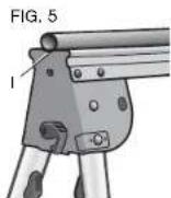
Working With Pipes (Fig. 5)
if cutting or otherwise working with pipe, the stand has a V notch (I) on each side of the stand to help keep the pipe from rolling when cutting.
Carry Strap
If you purchase the carry strap accessory for DEWALT stands, use the small square hole in the metal end to mount the accessory.
Wall Mount Storage
If you would like to store your stand out of the way you can mount your stand on the wall. Install a wood screw into a stud, leave a portion protruding from the wall. Use the V notch on the bottom of the metal end to hang the stand vertically on the screw.
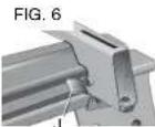
Locking Locator Clip (Fig. 6)
The locking locator clip (J) keeps the optional DW7231 accessory from sliding left or right during cutting operations. It is fixed on the DWX725.
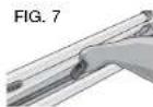
Carry Handle (Fig. 7)
A handle has been supplied to transport the work stand to and from the work site.
WARNING: To reduce the risk of personal injury, DO NOT attempt to store or carry the work stand with a tool attached. Loss of control may result.
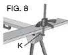
Clamping Work Material (Fig. 8)
The work stand is compatible with the DWS5026 track saw clamp. Insert the clamp's base into the large rectangular hole (K) in the stand end bracket and clamp down on your work material.
Accessories
WARNING: Since accessories, other than those offered by DEWALT, have not been tested with this product, use of such accessories with this tool could be hazardous. To reduce the risk of injury, do not create unstable conditions and use only with DEWALT tools.
COMPATIBLEPRODUCTS
DW7231 - Miter saw mounting brackets
DW7026-Carry strap
DWS5026 - TrackSaw™ clamp
Recommended accessories for use with your tool are available at extra cost from your local dealer or authorized service center. If you need assistance in locating any accessory, please contact DEWALT Industrial Tool Co., 701 East Joppa Road, Baltimore, MD 21286, call 1-800-4-DEWALT (1-800-433-9258) or visit our website www.dewalt.com.
English
Repairs
To assure product SAFETY and RELIABILITY, repairs, maintenance and adjustments should be performed by a DEWALT factory service center, a DEWALT authorized service center or other qualified service personnel. Always use identical replacement parts.
Three Year Limited Warranty
DEWALT will repair, without charge, any defects due to faulty materials or workmanship for three years from the date of purchase. This warranty does not cover part failure due to normal wear or tool abuse. For further detail of warranty coverage and warranty repair information, visit www.dewalt.com or call 1-800-4-DEWALT (1-800-433-9258). This warranty does not apply to accessories or damage caused where repairs have been made or attempted by others. This warranty gives you specific legal rights and you may have other rights which vary in certain states or provinces.
In addition to the warranty, DEWALT tools are covered by our:
1 YEAR FREE SERVICE
DEWALT will maintain the tool and replace worn parts caused by normal use, for free, any time during the first year after purchase.
90 DAY MONEY BACK GUARANTEE
If you are not completely satisfied with the performance of your DEWALT Power Tool, Laser, or Nailer for any reason, you can return it within 90 days from the date of purchase with a receipt for a full refund - no questions asked.
LATIN AMERICA: This warranty does not apply to products sold in Latin America. For products sold in Latin America, see country specific warranty information contained either in the packaging, call the local company or see website for warranty information.
FREE WARNING LABEL REPLACEMENT: If your warning labels become illegible or are missing, call 1-800-4-DEWALT (1-800-433-9258) for a free replacement.
DWALT INDUSTRIAL TOOL CO., BALTIMORE, MD 21286 U.S.A. FOR SERVICE INFORMATION CALL 1-400-4-DWALT www.DWALT.com
Établi industriel DWX725
Description
A. Longeron
Preparation (Fig. 2)
PRODUITS COMPATIBLES
Local D, Col. Obrera (55) 5588 9377
MERIDA,YUC
Calle 63 #459-A - Col. Centro (999) 928 5038
MONTERREY, N.L.
Av. Francisco I. Madero 831 Poniente - Col. Centro (818) 375 23 13
PUEBLA, PUE
17 Norte #205 - Col. Centro (222) 246 3714
QUERETARO, QRO
Av. San Roque 274-Col. San Gregorio (442) 2176314
SAN LUIS POTOSI. SLP
BOSQUES DE CIDROS, ACCESO RADIATAS NO.42
3A. SECCION DE BOSQUES DE LAS LOMAS
DELEGACION COAJIMALPA,
05120, MEXICO, D.F.
TEL. (52) 555-326-7100
R.F.C.BDE810626-1W7
DEWALT Industrial Tool Co., 701 East Joppa Road, Baltimore, MD 21286 (SEP10) Part No. N084925 DWX725 Copyright © 2010 DEWALT
The following are trademarks for one or more DEWALT power tools: the yellow and black color scheme; the "D" shaped air intake grill; the array of pyramids on the handgrip; the kit box configuration; and the array of lozenge-shaped humps on the surface of the tool.