
CS 1360 - Fridge LIEBHERR - Free user manual and instructions
Find the device manual for free CS 1360 LIEBHERR in PDF.
| Product type | Refrigerator-freezer combination, freestanding |
| Dimensions (approx.) | Height: 182 cm, Width: 70 cm, Depth: 77 cm |
| Weight (approx.) | 100 kg (packaged) |
| Electrical supply | 110-120 V, 60 Hz, 15 A (20 A for Side-by-Side) |
| Climate class | SN, N, ST, T (according to rating plate) |
| Freezing capacity | Up to 25 kg/24h (with SuperFrost) |
| Defrost system | Automatic (NoFrost) in both compartments |
| Quick refrigeration | SuperCool function (6-12 h) |
| Quick freezing | SuperFrost function (up to 65 h) |
| Ice maker | Integrated (optional), 90-130 ice cubes/24h |
| Interior lighting | LED, automatic shut-off after 15 min door open |
| Alarms | Door open, temperature, power failure |
| Child safety | Electronic key lock |
| Sabbath mode | Yes (120 h maximum) |
| Door reversal | Possible (Torx tools provided) |
| Water filter | Optional, replacement every 6 months |
| Maintenance | Clean with soft cloth and neutral detergent; annual dusting of condenser |
| Warranty | 2 years parts and labor, 5 years sealed system, 6-12 years sealed system parts |
Frequently Asked Questions - CS 1360 LIEBHERR
User questions about CS 1360 LIEBHERR
0 question about this device. Answer the ones you know or ask your own.
Ask a new question about this device
Download the instructions for your Fridge in PDF format for free! Find your manual CS 1360 - LIEBHERR and take your electronic device back in hand. On this page are published all the documents necessary for the use of your device. CS 1360 by LIEBHERR.
USER MANUAL CS 1360 LIEBHERR
Combined fridge-freezer, freestanding/semi built-in
Mode m ploi
1 The appliance at a glance. 2
1.1 Additional benefits 2
1.2 Overview of the appliance and its equipment... 3
1.3 Range of appliance use 3
1.4 Conformity 3
1.5 Installation dimensions 4
1.6 Energy saving. 4
1.7 Example of food arrangement 4
2 General safety information. 4
3 Controls and displays. 5
3.1 Operating and control elements.. 5
3.2 Temperature display 6
4 Start-up 6
4.1 Transporting the appliance.. 6
4.2 Setting up the appliance.. 6
4.3 Changing the door hinges.. 7
4.4 Side-by-side installation 17
4.5 Water connection 13
4.6 Installation into a fitted kitchen 14
4.7 Anti-tip device 15
4.8 Installing the water filter 15
4.9 Disposal of packaging 17
4.10 Connecting the appliance 17
4.11 Switching on the appliance 17
5 Operation 18
5.1 Temperature display unit 18
5.2 Brightness of the temperature display 18
5.3 Child-proof lock. 18
5.4 Door alarm 19
5.5 Temperature alarm 19
5.6 Sabbath Mode 19
5.7 Fridge compartment 20
5.8 Freezer compartment 22
6 Maintenance 24
6.1 Replacing the water filter 24
6.2 Defrosting with NoFrost.. 25
6.3 Cleaning the appliance.. 25
6.4 Cleaning the IceMaker 26
6.5 Customer service 26
6.6 Appliance Information 26
7 Troubleshooting 26
8 Putting appliance out of service 29
8.1 Vacation Tips 29
8.2 Switching off the appliance 30
8.3 Decommissioning 30
9 Disposing of the appliance. 30
10 Liebherr Warranty Plan. 30
Congratulations on the purchase of your new appliance. With this purchase, you have chosen all the advantages of the latest refrigeration technology, guaranteeing you a high-quality appliance with a long life span and high operating safety.
The equipment of your appliance gives you the highest level of day-to-day ease of operation.
Together we are making an active contribution to the conservation of our environment by purchasing this appliance which is manufactured in an environmentally friendly process with the use of recyclable materials.
We hope you enjoy your new appliance.
The manufacturer is constantly working to improve all models. Therefore please understand that we reserve the right to make design, equipment and technical modifications.
To get to know all the benefits of your new appliance, please read the information contained in these instructions carefully.
The instructions apply to several models, so there may be differences. Sections which only apply to certain appliances are indicated with an asterisk (^*)
Instructions for action are marked with a , the results of action are marked with a
1 The appliance at a glance
1.1 Additional benefits
CFC free
- Energy-optimized refrigerant circuit
- Energy-efficient insulation
- Low energy consumption
-User-friendly electronic controls
Active function indicators
- Temperature can be controlled in the appliance independent of ambient conditions according to its climate rating - Temperature can be displayed as ^ C or ^ F
- The appliance defrosts automatically - no need to spend time defrosting
Large refrigeration capacity
- Safety glass storage shelves
- Adjustable door shelves for tall bottles
Large freezing capacity
- Shelves can be removed to make space for large items.
- Freezer over-temperature alarm
- Quick-freeze feature for fresh food (SuperFrost)
- Frozen food temperature indicator
- Power failure/frost-control display
- All freezer drawers suitable for quick-freeze
Bright LED interior light
- Door ajar alarm
- Handle grips on all extra-large drawers for easy transport
- Integrated transport grips on appliance housing
- Transport castors at back
Easy to clean
- Door hinges can be reversed
- This unit is certified as Sabbath compliant by the Star-K organization thus allowing the appliance to be used during religious holidays. For more information please visit Star-K on the web at www.star-k.org.

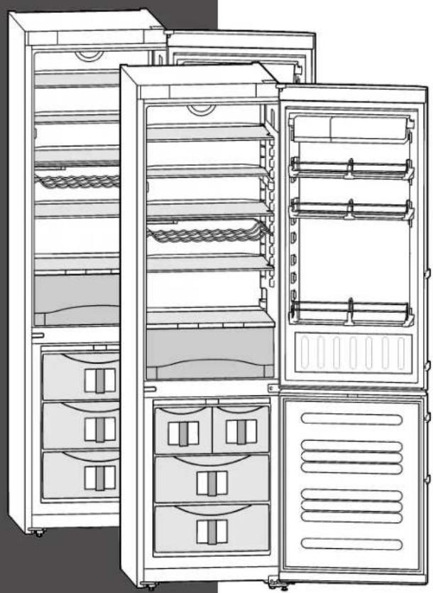
1.2 Overview of the appliance and its equipment
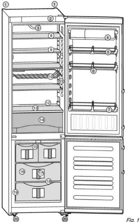
(1) Rear transport handles
(11)Interior light
(2) Operating and control elements
(12)Drain hole
(3) Fan (13)Coldest zone
(4) Container shelf (14)Vegetable drawer
(5) Door rack, moveable (15) IceMaker*
(6) Bottle partition, adjustable
(16)Freezer compartment
(7) Gallon-capacity rack (17)InfoSystem
(8) Shelf, moveable (18)VarioSpace
(9) Shelf, can be split (19)Rating plate
(10)Bottle shelf (20)Adjustable feet, front transport handles, rear transport castors
1.3 Range of appliance use
Normal use
The appliance is only suitable for refrigerating food in a domestic environment or an environment that is similar to a domestic one. This includes, for example, use
- in staff kitchens, bed and breakfast establishments.
- by guests in country homes, hotels, motels and other types of accommodations,
- for catering and similar wholesale services.
Use the appliance only for normal household purposes. All other types of uses are not permitted.
Foreseeable misuse
The following uses are specifically prohibited:
- Storage and cooling of medication, blood plasma, laboratory preparations or similar substances and products in accordance with the CMDCAS and FDA 510(k)
- Use in areas at risk of explosion
Incorrect appliance use can cause damage to the stored products or cause them to spoil.
Climate ratings
The appliance is set to operate within specific ambient temperature limits according to its climate rating. The climate rating for your appliance is printed on the rating plate.
Note
Compliance with the specified ambient temperatures is required, otherwise the refrigeration performance is reduced.
| Climate rating | for ambient temperatures from |
| SN | 50 °F (10 °C) to 90 °F (32 °C) |
| N | 61 °F (16 °C) to 90 °F (32 °C) |
| ST | 61 °F (16 °C) to 101 °F (38 °C) |
| T | 61 °F (16 °C) to 110 °F (43 °C) |
1.4 Conformity
The refrigerant circuit has been tested for leaks. The appliance complies with the relevant safety regulations and the directives UL250 and CAN/CSA C22.2 No.63-93.
Instructions for testing institutes:
Tests must be carried out in accordance with the applicable standards and guidelines.
The preparation and testing of the appliance must be Dust deposits increase energy carried out taking account of the manufacturer's consumption: loading plans and the instructions in the operating - Once a year the dust should manual . removed from the refrigeratio
1.5 Installation dimensions
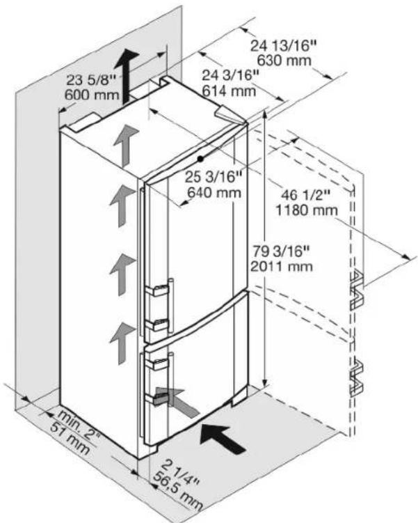
Fig. 2
1.6 Energy saving
- Always ensure good ventilation. Do not obstruct ventilation openings or grilles.
- Do not install the appliance in direct sunlight or next to an oven, heater, or similar heat source.
- Energy consumption depends on installation conditions such as the ambient temperature (see 1.3).
- Avoid opening the appliance door for any longer then neccessary.
- The lower the temperature is set the higher the energy consumption.
- Store food logically (see The appliance at a glance).
- All food stored in the appliance should be well wrapped and covered. This prevents frost buildup.
Only take food out for as long as necessary so that it does not get too warm. - Storing hot food: let it cool to room temperature first.
- Defrost frozen food in the fridge.
1.7 Example of food arrangement
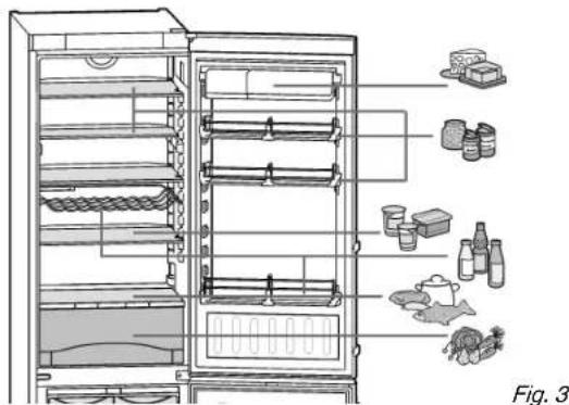
Fig. 3
2 General safety information
Read and follow these instructions. They contain safety advice which is important for safe and problem-free installation and operation. Always read and follow the safety advice.
Dangers for the user:
This appliance can be operated by children 8 years and older as well as by persons with reduced physical, sensory or mental capabilities or lack of experience and knowledge if they are supervised or have been instructed in the safe use of the appliance and understand the associated risks. Children must not play with the appliance. Cleaning and user maintenance must not be performed by children unless they are supervised.
- When disconnecting the appliance from the outlet, always take hold of the plug. Do not pull on the cable.
- Disconnect the power plug or switch off the power if a fault occurs.
- Do not damage the mains power line. Do not operate the appliance from a defective mains power line.
- Repairs, work on the appliance and replacement of the power cord should only be carried out by the customer service department.
- The appliance should only be assembled, connected and disposed of in accordance with the instructions.
- Please keep the instructions and pass them on to any future owner.
- All repairs to or work on the IceMaker must only be carried out by the customer service department or other specialist engineers trained to do this.*
- The manufacturer is not liable for damage arising from incorrect connection to the water supply.*
Risk of fire:
- Do not operate the appliance near explosive gases.
- Do not store explosive materials or spray cans with flammable propellants, such as e.g. butane, propane, pentane, etc. in the appliance. You can recognize such spray cans by the printed contents or a flame symbol. Any leaking gasses can be ignited by electrical components.
- Keep burning candles, lamps and other objects with open flames away from the appliance so that they do not set it on fire.
Alcoholic beverages or other containers holding alcohol must always be tightly sealed for storage purposes. Any leaking alcohol can be ignited by electrical components
Tipover hazard:
- Do not stand or climb on the base, drawers, doors, etc. This applies in particular to children.
Risk of food poisoning:
- Do not consume food that has passed its best before date.
Danger of frostbite, feelings of numbness and pain:
- Avoid continued skin contact with the cold surfaces or chilled/frozen food or adopt protective measures, e. g. use gloves. Do not consume ice cream (especially sherbets) and ice cubes immediately when they are too cold.
Risk of injury and damage:
- Hot steam may lead to injuries. Do not use any electrical heating or steam cleaning equipment, naked flames or defrosting sprays for defrosting
- Do not remove ice with sharp objects
Risk of crushing:
- Do not hold onto the hinge when opening and closing the door. Fingers may get caught.
Follow the specific instructions in the other sections:
| ! | DANGER | indicates a hazardous situation, which if not avoided, will result in death or serious injury. |
| ! | WARNING | indicates a hazardous situation, which if not avoided, could result in death or serious injury. |
| ! | CAUTION | indicates a hazardous situation, which if not avoided, will result in minor or moderate injury. |
| NOTICE | indicates a hazardous situation, which if not avoided, could result in damage to property. | |
| Note | indicates useful advice and tips. |
3 Controls and displays
3.1 Operating and control elements
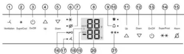
Fig. 4
(1) Ventilation button
(2) SuperCool button
(3) Fridge compartment On/Off button
(4)Fridge compartment Up button
(5) Fridge compartment Down button
(6) SuperCool symbol
(7) Power failure symbol
(8)Fridge compartment temperature display
(9) Alarm symbol
(10)IceMaker symbol*
(11)Freezer compartment Up button

The touch point is located between the symbol and the symbol label.
Start-up
3.2 Temperature display
The following is displayed in normal operation:
- the highest freezer temperature
- the average fridge temperature
The freezer compartment temperature display is flashing:
- the temperature setting has been changed
- after switch-on the temperature is not yet cold enough
- the temperature has risen several degrees
Dashes are shown on the display:
- the freezer temperature is above 32^ (0^) .
The following displays indicate malfunction. Possible causes and corrective actions: (see Troubleshooting).
- F0 through F9
- FE*
The power failure symbol LED flashes.
4 Start-up
4.1 Transporting the appliance

CAUTION
Risk of injury or damage if incorrectly transported.
Transport the appliance in its packaging.
Transport the appliance upright.
Do not move the appliance on your own.
4.2 Setting up the appliance

WARNING
Risk of fire due to moisture!
If live parts or the power cord get wet, this can cause a short circuit.
The appliance is designed for use in enclosed spaces. Do not operate the appliance in open space or in damp areas or where there is spray.

WARNING
Risk of fire due to short circuit.
If the power cable or plug of the appliance or another appliance and the back of the appliance touch each other the power cable or plug will be damaged by the vibrations of the appliance which could lead to a short circuit.
Install the appliance so that it does not touch any plugs or power cables.
Do not connect the appliance or other appliances to the sockets on the back of the appliance.

WARNING
Danger of fire and damage!
Do not place devices that give off heat, e.g. microwaves, toasters, etc. on the appliance.

CAUTION
Risk of personal injury!
Have two people move this appliance into place.

WARNING
Danger of fire and damage due to blocked ventilation openings!
- Never block the ventilation openings. Always ensure good ventilation!
NOTICE
Risk of damage caused by condensation Installing the appliance next to any other refrigerator or freezer can cause condensation or damage to the Lieb-herr appliance.
- Do not install this appliance next to any other refrigerator or freezer except another Liebherr model. Liebherr models are designed to allow side-by-side installation. They are equipped with a heating system to eliminate condensation when refrigerators or freezers are installed side-by-side.
NOTICE
Risk of damage for the finished floor surface!
Protect the finished floor surface before you uncrate the unit.
Verify that:
The floor under the appliance is flat and level.
The floor can support the appliance's weight plus approximately 1200 pounds (544kg) of food weight.
The appliance is not placed in direct sunlight or near the stove, range top, radiators and similar heat sources.
Examine the unit and packaging for shipping damage. Contact the carrier immediately if you suspect there is any damage.
Note the type (model, number), index, appliance/serial number, date of purchase and where purchased (see 6.6).
Remove anything attached to the rear or side walls of appliance that would prevent proper installation or impede proper ventilation.
Remove the protective film from the outside of the appliance.
NOTICE
The stainless steel doors are treated with a high-grade surface coating and must not be cleaned with the supplied cleaning agent.

This would damage the surface coating.
Wipe the coated door surfaces using a soft, clean cloth only.
Apply a stainless steel cleaner only to the stainless steel side walls evenly, wiping with the grain. Subsequent cleaning becomes easier as a result.
Wipe painted side walls with a clean, soft cloth only.
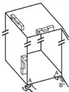
Align the appliance so that it stands firmly and on a level by applying the accompanying spanner to the adjustable-height feet (A) and using a spirit level.
Then support the door: Extend the adjustable foot at the turn hinge (B) until it rests on the floor and then make a further 90^ turn.
Note
Clean the appliance (see 6.3).
If the appliance is set up in humid areas, condensation may build on the outside of the appliance.
Always ensure proper ventilation.
Note
If the gap between the rear of the appliance and the wall is less than 2 in. (51 mm), the power consumption level may increase.
4.3 Changing the door hinges
You can reverse the door hinges, if necessary:
Make sure you have the following tools on hand:
Torx® 25
Torx 15
Screwdriver
Cordless screwdriver, if necessary
Another person to help with the installation, if necessary
SW2 Allen key (supplied)
4.3.1 Remove upper soft stop damper
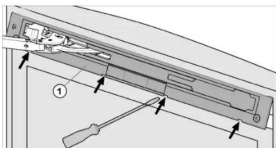
Fig. 5
Open upper door.
NOTICE
Risk of damage!
If the door seal is damaged the door may not close properly and the level of cooling is insufficient.
Do not damage the door seal with the screwdriver!
Release panel Fig. 5 (1) using a slotted screwdriver and remove.
The panel hangs above the damper bracket.
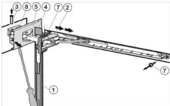
Fig. 6
Push panel forward over the damper bracket Fig. 6 (4) in the direction of the appliance.
Engage locking device Fig. 6 (2) into place inside oblong hole.
The locking device prevents the hinge from snapping shut.
Unscrew cover Fig. 6 (5) that is on the hinge side until the first notch using a screwdriver.
The bolt will become visible.
Push bolt Fig. 6 (3) out from below.
Press damper bracket Fig. 6 (4) in the direction of the door.
Completely loosen cover Fig. 6 (5) that is on the hinge side and remove.
Remove panel Fig. 6 (1).
- Loosen cover that is on the hinge side Fig. 7 (6) using a screwdriver and remove by pulling outwards.
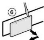
Fig. 7
Start-up
Unscrew soft stop unit (2 x Torx® 15) Fig. 6 (7).
Slightly pull out soft stop unit, push it towards the handle side and open it out.
Set soft stop unit to the side.
Unscrew bearing part Fig.68),turn it 180^ and move it to the opposite side. Make preliminary holes (optional) or use a cordless screwdriver.
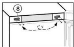
Fig. 8
To prevent food items from falling out, take all food out of the door racks before removing the door.
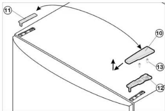
Fig. 9
Close upper door.
▶ Pull cover Fig. 9 (10) forward and upwards to remove.
Lift off cover Fig. 9 (11).

CAUTION
Risk of injury if the door tips out!
- Keep a steady grip on the door.
Set the door down carefully.
Unscrew upper bearing bracket Fig. 9 (12)2 x Torx® 25) Fig. 9 (13) and pull it upwards to remove.
Lift the upper door up and off and set it to the side.
4.3.3 Remove lower soft stop damper
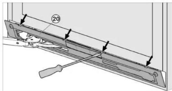
Fig. 10
Open the lower door.
NOTICE
Risk of damage!
If the door seal is damaged the door may not close properly and the level of cooling is insufficient.
Do not damage the door seal with the screwdriver!
▶ Release panel Fig. 10 (20) using a slotted screwdriver and remove.
The panel hangs above the damper bracket
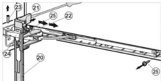
Fig. 11
Push panel forward over the damper bracket Fig.11 (24)in the direction of the appliance.
Engage locking device Fig. 11 (22) into place inside oblong hole.
The locking device prevents the hinge from snapping shut
Lift off cover Fig. 11 (21) from the outside using a screwdriver and remove by pulling outwards.
Tip the appliance rearwards with the help of a second person if needed.
Push bolt Fig. 11 (23) out from below.
Press damper bracket Fig. 11 (24) in the direction of the door.
Remove panel Fig. 11 (20)
Unscrew entire soft stop unit (2 x Torx® 15) Fig. 11 (25).
Slightly pull out soft stop unit, push it towards the handle side and open it out
Set soft stop unit to the side
4.3.4 Removing the lower door
Close the lower door.
Pull center bearing pin Fig. 12 (32) and disc Fig. 12 (34) out of the bearing bracket and the lower door.
Remove plastic cap Fig. 12 (33).

CAUTION
Risk of injury if the door tips out!
- Keep a steady grip on the door.
Set the door down carefully.
Open the lower door.
Unscrew center bearing bracket Fig. 12 (31) (2 x Torx® 25).
Lift lower door upwards to remove and set it to the side
4.3.5 To swap over central bearing parts
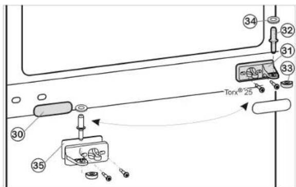
Fig. 12
Carefully remove cover trim Fig. 12 (30).
Turn the center bearing bracket Fig. 12 (31) and washer Fig. 12 (35) 180^ and secure tightly (to 4 Nm) on the new hinge side.
Turn the cover trim Fig. 12 (30) 180^ and snap it back into place on the new handle side.
4.3.6 To swap over lower bearing parts
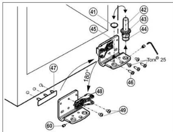
Fig. 13
Unscrew grub screw Fig. 13 (60) by approx. 1 turn using the socket wrench supplied.
Unscrew the bearing pin Fig. 13 (42), with disc Fig. 13 (43) and positioning foot Fig. 13 (44), in an upwards direction.
Lift off plug Fig. 13 (41).
Unscrew Fig. 13 (46) bearing bracket Fig. 13 (45).
Completely unscrew the grub screw Fig. 13 (60) and screw it into the opposite side of the bearing bracket until it is externally flush with the bearing bracket.
Unscrew bearing part Fig. 13 (48), turn it 180^ and tighten Fig. 13 (49) it to the inside.
Insert plug Fig. 13 (41) back into the other hole.
Carefully lift off the cover on the handle side Fig. 13 (47) and move it to the opposite side.
Using a cordless screwdriver if necessary, again secure the bearing bracket Fig. 13 (45) on the new hinge side tightly (to 4Nm ).
Screw complete bearing pin Fig. 13 (42), with disc and positioning foot, back into place again.
Tighten grub screw Fig. 13 (60).
4.3.7 Swapping the handles
For both the upper and lower door:
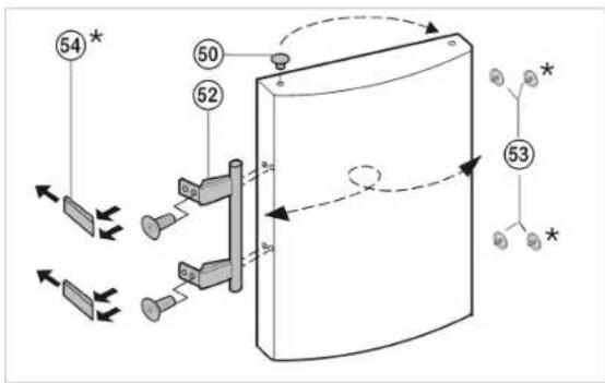
Fig. 14
Pull plugs Fig. 14 (50) out of the door bearing bushes and move them to the other side.
- Detach the door handle Fig. 14 (52), plug Fig. 14 (53) and pressure plates* Fig. 14 (54) and move them to the opposite side.
- When fitting the pressure plates on the opposite side, make sure they engage correctly.
4.3.8 Fitting the lower door
Position the lower door from above onto the lower bearing pins Fig. 13 (42).
Close the door.
Place the plastic cap Fig. 12 (33) back onto the center bearing bracket Fig. 12 (31).
Insert the center bearing pin Fig. 12 (32) on the new hinge side through the center bearing bracket Fig. 12 (31) into the lower door.
Place disc Fig. 12 (34) onto the center bearing pin Fig. 12 (32)
4.3.9 Fitting the lower soft stop damper
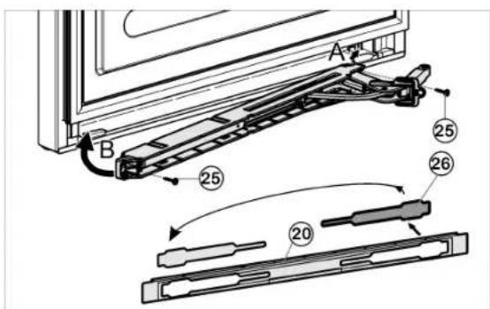
Fig. 15
Loosen cover Fig. 15 (26) from the panel Fig. 15 (20) and insert on the other side.
- With the hinge of the soft stop unit facing the door hinge side, engage the soft stop unit (A) and swivel inwards (B)
The holes on the left and right must lie exactly above each other
Tightensoftstopunit(2xTorx®15)Fig.15(25).
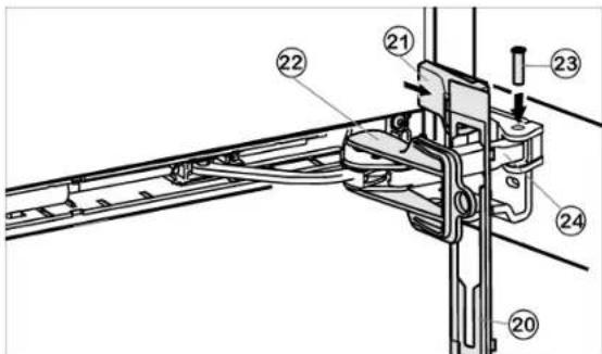
Fig. 16
Hook panel Fig. 16 (20) into the damper bracket such that the detent hooks are pointing forwards and the front side is facing the appliance.
Pull damper bracket Fig. 16 (24) towards bearing bracket and insert bolt Fig. 16 (23) from above such that the square is resting in the recess.
Position cover Fig. 16 (21) and snap in.
Check that the cover is positioned correctly such that the door can close properly and the bolt is secured
Remove locking device Fig. 16 (22) by twisting it.
Snap panel Fig. 16 (20) into place on the door
Close the lower door.
Place the upper door onto the center bearing pin Fig.1232
Insert the upper bearing bracket Fig. 9 (12) on the new hinge side into the door.
- Tighten the upper bearing bracket (to 4 Nm)(2 x Torx® 25) Fig. 9 (13). Make preliminary holes (optional) or use a cordless screwdriver.
Snap both cover Fig. 9 (11) and cover Fig. 9 (10) into place on the opposite side.
Leave upper door open.
4.3.11 Fitting the upper soft stop damper
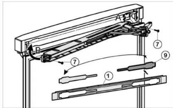
Fig. 17
- Loosen cover Fig. 17(9) from the panel Fig. 17(1) and insert on the other side.
With the hinge of the upper soft stop unit facing the door hinge side, engage the soft stop unit (A) and swivel inwards (B)
The holes on the left and right must lie exactly above each other
Tighten soft stop unit (2 x Torx® 15) Fig. 17(7).
Note
Follow the correct sequence First hang the panel over the damper bracket, then the cover
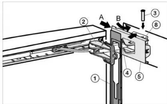
Fig. 18
Hook panel Fig. 18 (1) into the damper bracket Fig. 18 (4) such that the detent hooks are pointing inwards and the front side is facing the appliance.
Push on cover Fig. 18 (5) from the outside (A) and pivot over the bearing part Fig. 18 (8) (B).
Place cover Fig. 18 (5) on top and allow to snap into place until the first notch.
The openings for the bolts lie above each other after positioning the damper bracket
Pull damper bracket Fig. 18 (4) towards bearing bracket and insert bolt Fig. 18 (3) from above such that the square is resting in the recess.
Now snap cover Fig. 18 (5) completely into place on the bearing part Fig. 18 (8).
Check that the cover is positioned correctly such that the door can close properly and the bolt is secured
Remove locking device Fig. 18 (2) by twisting it.
Snap panel Fig. 18(1) into place on the door.
Turn cover Fig. 7(6) 180^ from the handle side, place it on top from the outside and snap into place.
4.3.12 Aligning the doors
Align the doors flush with the appliance housing, using the two oblong holes in the lower bearing bracket Fig.1345) and in the center bearing bracket Fig.1231 as a guide, if needed. To do so, unscrew the center screw on the lower bearing bracket Fig.1345).

WARNING
Risk of bodily injury due to the door falling off. If the bearing parts are not installed with the proper torque, the door may fall off. In addition, the door may not close, thus impairing the cooling performance of the appliance.
- Securely tighten the bearing brackets by applying a torque of 3 lb-ft (4 Nm).
Check all screws and retighten if necessary.
4.4 Side-by-side installation
As seen from the front, install the appliance with an IceMaker on the right and the appliance without an IceMaker on the left.
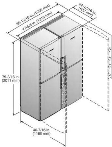
Fig. 19
The fixing accessories are supplied with model CS 1311. If you have model CS 1360 you can purchase the fixing accessories by contacting customer services.
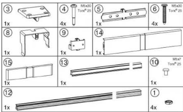
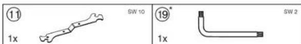
Fig. 20
Fig. 21
Make sure you have the following tools on hand:
Spirit level
Cordless screwdriver
Torx® 25 screwdriver
Open-end wrench, SW 10 (supplied)
1/4 in. socket
Allen wrench, SW 2 (supplied)
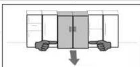
Tips on moving the combination:
Before assembly, set the appliances up as close as possible to the final location.
- When moving the appliances, always grasp the front outside corners. Never press your knee against the side walls or door.
The easiest way to move the combination is diagonally, by moving the left and right corner in turn. If the combination is positioned exactly in front of the recess, slide it in straight.
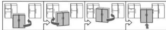
If you need to pull the combination back out of the recess, grasp it in the bottom third and pull forward.
NOTICE
Moving the SBS combination may result in damage! The assembled SBS combination is heavy. If not moved properly, the appliance may become dented.
Read and follow the moving tips (see above).
Remove all protective films from the housing exterior.
Front of the appliance:
Start-up
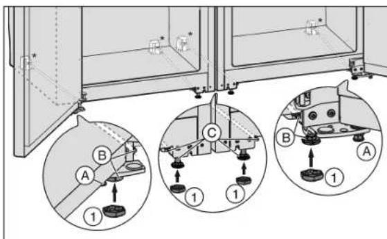
Fig. 22
If necessary screw in the adjustment feet Fig.22A at the front of both appliances completely so that there is no floor contact.
Place the caps Fig. 22 (1) on the four front adjustment feet.
Move both units together so that there is a gap of up to approx. 3 / 8 (10 mm) between them so that they are flush as seen from the front.
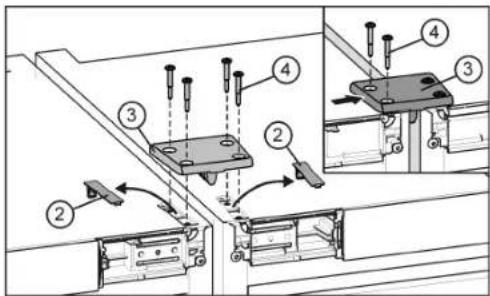
Fig. 23
▶ Release and remove the covers Fig. 23 (2).
The appliances are automatically aligned in height with the connecting plate. If one appliance is somewhat higher than the other start with this one.
Fit a connecting plate Fig. 23 (3) and fix loosely to one appliance with two screws Fig. 23 (4).
- Move the connecting plate to the side so that the centre bar of the plate is touching the side wall of the appliance. Tighten the screws.
Screw the connecting plate to the second appliance too. If necessary push the appliances together or apart a little.
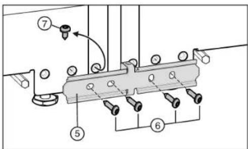
Fig. 24
If your appliance has been fitted with the pre-fitted screw Fig.24 (7): Undo the screw.
The appliances are automatically aligned in depth with the connecting sheet. If one appliance projects further forward than the other start with this one. Otherwise start with the left hand appliance.
Fix the connecting sheet Fig. 24 (5) loosely to one appliance with two screws Fig. 24 (6).
Move the connecting sheet to the side so that the centre bar of the sheet is touching the side wall of the appliance. Tighten the screws.
Screw the connecting sheet to the second appliance too. If necessary push the appliances together or apart a little.
Back of the appliance:
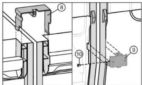
Fig. 25
Place the connecting clamps Fig.25 (8) at the top of the centre side walls.
Insert the connecting angle Fig. 25 (9) underneath into the corresponding space.
If the connecting angle is somewhat loose, fit a screw Fig.25 (10).
Note
To prevent vibration noise, the brackets and screws must not come into contact with the clamps or the screws on the pipework on the back.
Front of the appliance:
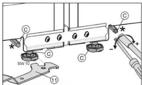
Fig. 26
NOTICE
Risk of damage to the castors.
Do not use a power tool to adjust the rear adjustment feet as it will damage the leveling mechanism or disengage the rod - instead use a hand ratchet.
The front adjustment feet can be adjusted with the supplied open-end wrench Fig.26 (11) and the rear adjustment feet* with a 1 / 4'' bit attachment.
- Tighten the centre adjustment feet Fig. 22 (C) so that there is no floor contact.
Align the combination with the outer adjustment feet Fig.22(B).
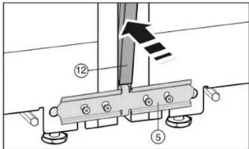
Fig. 27
Before inserting the trim Fig.27(12) squeeze the two fillets together along the entire length. The trim can now be inserted more easily into the gap. When pressing in the trim, use a soft cloth to prevent dents on the surface of the trim. Press the trim carefully and evenly into the gap to achieve the best possible fit.
On the front press the long trim Fig. 27 (12) into the vertical gap. Ensure that the trim rests on the connecting panel Fig. 27 (5).
Remove protective film from the trim.*
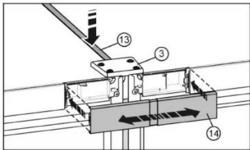
Fig. 28
On the top, press the short trim Fig. 28 (13) into the gap. The trim must form a flush finish with the connecting plate Fig. 28 (3) on the front edge.
Snap the cover Fig. 28 (14) onto the open space between the two control panel trims. Make sure that the outer surfaces of the cover form a flush finish with the control panel trims. The cover can be extended for this purpose.
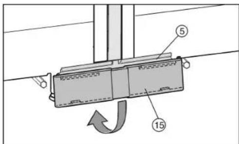
Fig. 29
Position the lower cover Fig. 29 (15) from above onto the connecting panel Fig. 29 (5) and snap it down into place.
Connect the combination unit to the power supply (see 4.10). Appliances with IceMaker:
Connect the appliance to the water supply (see 4.5). All appliances
Fit the anti-tip device (see 4.7).
NOTICE
Moving the SBS combination may result in damage! The assembled SBS combination is heavy. If not moved properly, the appliance may become dented.
Read and follow the moving tips (see above).
Carefully push the combination into the designated position.
Align the combination again if necessary using the adjustment feet.
Lower thecentre adjustment feet Fig. 22(C) again until they touch the floor.
Then shore up the door: Lower the adjustment feet Fig.22 (A) onto the bearing bracket until they contact the floor then turn 90^ again.
The door height can be adjusted at the lower outside bearing brackets:
Unscrew the threaded pin Fig.30 (17) a little (no more than one turn).
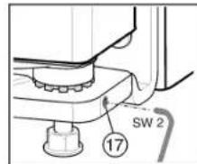
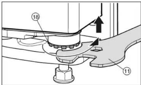
Fig. 30
Fig. 31
To lift the door unscrew the bearing pin Fig. 31 (18) clockwise using the supplied open-end wrench Fig. 31 (11). The appliance is delivered from the factory with the bearing pin screwed in completely.
Screw the threaded pin Fig. 30 (17) in again to fix the bearing pin.
4.5 Water connection*

WARNING
Electrical Shock Hazard!
Do not make the water connection while the appliance is connected to an electrical outlet.
- Disconnect the water supply before connecting the water lines for the IceMaker.
The connection to the water supply may only be made by a trained and licensed plumber.
Start-up

WARNING
Poisoning Hazard!
The water quality must comply with the drinking water regulations for the geographical area where the appliance is located.
Connect to potable water supply only.
The IceMaker is designed exclusively to make ice cubes in quantities needed by a household and must only be operated with water appropriate for this purpose.
| Water pressure: | |
| psi MPa (bars) | |
| 21.76 to 87.02 | 0.15 to 0.6 (1.5 to 6) |
If a water filter is used, the instructions on water pressure in the Installing the water filter section apply.
- Water must be supplied to the appliance through a cold water pipe that complies with hygiene standards and can withstand the operating pressure.
- All devices and equipment used to supply water must comply with the regulations in force in the respective country.
- The solenoid valve is located at the bottom of the back of the appliance. It has a metric R3/4 connecting thread.
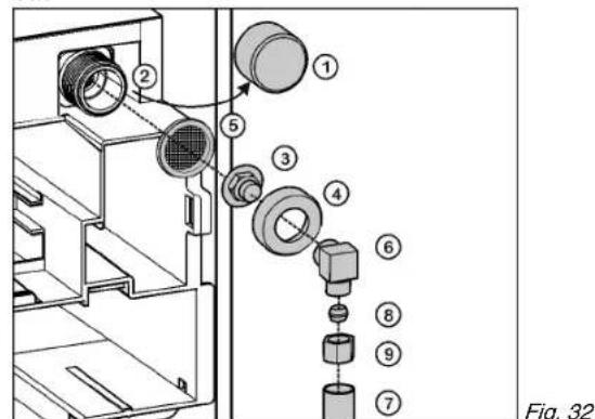
Remove the cap Fig. 32 (1) from the solenoid valve Fig.32(2).
Insert the coupler Fig. 32 (3) in theunion nut Fig. 32 (4).
Insert the water filter Fig. 32 (5) with the recess pointing down towards the coupler Fig. 32 (3).
NOTICE
Risk of damage to the water filter!
If you insert the filter incorrectly you could damage it.
Insert the filter with the recess pointing towards the coupler.
Lock the union nut Fig. 32 (4) onto the solenoid valve Fig. 32 (2) and tighten.
NOTICE
Risk of damage to the thread!
Do not overtighten the union nut.
To turn the water connection 90^ tighten the elbow connector Fig. 32 (6) if necessary.
Connect the water supply Fig. 32 (7) (e.g. copper) with the aid of the clamp ring Fig. 32 (8) and nut Fig. 32 (9) to the coupler Fig. 32 (3) or elbow connector Fig. 32 (6). Before fitting into the cabinet:
Check the whole water system for leaks.
Before using for the first time:
Have the water line bled (remove air) by a competent professional.
NOTICE
Malfunction of the water intake!
If the water intake is shut off during operation but the IceMaker remains in operation, the water intake pipe may ice up.
Switch off the IceMaker if the water supply is interrupted (e.g. holiday).
4.6 Installation into a fitted kitchen
Fig. 33
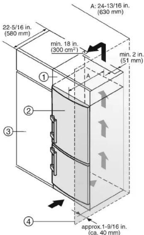
(1) Top cupboard (3) Kitchen cabinet
(2) Appliance (4) Wall
The appliance can be built into the range of kitchen units. To bring the appliance Fig.332 up to the height of the fitted kitchen units, a suitable top cupboard Fig.331 can be added above the appliance.
When converting kitchen cabinets (max. depth 22-5/16" (580 mm)) the device can be set up directly beside the kitchen cabinet Fig.33 (3). The appliance door projects (34 mm) at the side and in the center of the appliance (50 mm) from the front of the kitchen cabinet. This allows it to open and close properly.
Ventilation requirements:
- There must be a ventilation shaft at least 2" (51 mm) deep at the back of the top cupboard over the entire width of the top cupboard.
- The cross section of the ventilation gap below the ceiling must be at least 46.5 in ^2( 300 cm^2) .
- The bigger the ventilation gap, the more energy-saving the operation of the appliance.
If the appliance is installed with the hinges next to a wall Fig.33 (4), the gap between the appliance and the wall must be at least 1-9/16" (40 mm). This is how far the handle protrudes when the door is open.
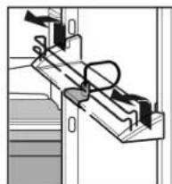
4.7 Anti-tip device
The screws for fastening the anti-tip device are not supplied with the appliance. Appropriate screws must be used for the material (wood, concrete, etc.) in which the safety device is mounted.

WARNING
Risk of injury if the appliance tips over!
Install the anti-tip device to prevent the appliance from tipping over when the fully loaded door is open.
NOTICE
Risk of damage due to leaking water! If the tilt safety device has been fitted in another position than the one given, the water hoses may be damaged when pushing the appliance into the niche.
Only fit the tilt safety device in the position shown in the diagram.
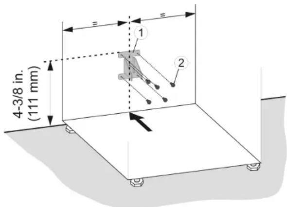
Fig. 34
Mark the installation position for the anti-tip device on the wall or back of the unit.
Install the anti-tip device Fig. 34 (1) using appropriate screws Fig. 34 (2).
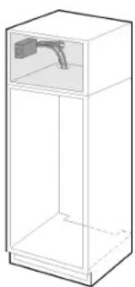
4.8 Installing the water filter*
The water filter ensures optimum water quality and is available as an accessory. It should be installed near the appliance in the cabinet, for example in the adapter cabinet above the appliance. To connect the filter to the appliance, it may be necessary to make an opening (C) in the floor of the adapter cabinet through which the hoses will be routed. Depending on your installation setup, you can route the two water filter hoses either through the rear panel or through the base of the cabinet. The maximum length of the water hose is 118-1/8" (3 m).
Alternatively, the appliance can also be operated without the water filter.
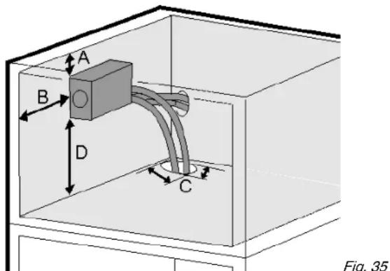
(A) 13/16 in (20mm)
(C) 1-3/16in. x 3/8in. (30mm x 10mm)
(B) 3-15/16 in (100mm)
(D) min. 4 in (100mm)
Start-up
The filter cover must be installed during assembly, so leave sufficient space around the filter module. Maintain the dimensions shown in Fig. 35 so that the filter can be replaced and the cover can be removed.
| Flow rate 0.5 gpm (1.89 lpm) |
| Water connection Drinking water |
| Water pressure 40 psi - 90 psi (2.8 bar - 6.2 bar/0.28 MPa - 0.62 MPa) |
| Water temperature 33 °F - 100 °F (0.6 °C - 37 °C) |
| Capacity 300 gal. (1.14 l) |

WARNING
Consuming contaminants can be harmful to your health!
If there is a chance the water may contain harmful bacteria or if the water quality is unknown, do not use this system without appropriate disinfection measures upstream or downstream of the system.
NOTICE
Leakage water may damage the system!
Do not install this system on hot water lines. The maximum operating temperature of the water in this system is 100^ (37.7^)
This system MUST be installed and used in compliance with federal and local installation regulations.
Do not install under water hammer conditions. A water hammer arrestor must be used to prevent water hammering. If you are unsure how to check these conditions, consult a professional installer.
Do not install with a water pressure greater than 90 psi (6.2 bar). If your water pressure exceeds 80 psi, install a pressure limiting valve. If you are unsure how to check the water pressure, consult a professional installer.
Protect against frost; if temperatures below 33^ (0.6^) are expected, remove the filter.
- When used as indicated, the disposable filter cartridges must be replaced every 6 months or whenever you notice a considerable decrease in the flow rate.
- Disconnect the appliance from the mains.
- Close off the main water supply if the appliance has already been connected to the tap.
Position appliance in front of the recess.
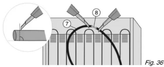
▶ Slice open the water hose Fig. 36 (7) located behind the appliance both in front of and behind the connector Fig. 36 (8) (90^ to direction of hose).
When doing so, make sure the hose does not become kinked and the cross-section of the hose remains round.
Connect the supplied extension hoses Fig. 37 (1) to the appliance hoses Fig. 37 (7): Slide the appliance hoses into the connectors as far as they will go (approx. 25/32" (20mm)
Pull the tray Fig. 38 (4) out until it catches.
- Secure the module with 4 screws Fig. 38 (5) through the recesses in the front and directly through the module in the back.
- Shorten hoses if necessary ( 90^ to direction of hose). The hoses should be long enough to allow the appliance to be pulled out of the recess even when it is connected to the water filter.
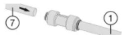
Fig. 37
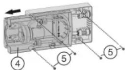
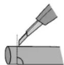
Fig. 38
Make sure the hoses do not become kinked and the cross-section of the hose remains round.
On the thin hose measure the insertion depth (E) of 21/32" (17 mm) and make a mark.
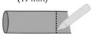
On the thick hose measure the insertion depth (E) of 25/32" (20 mm) and make a mark.
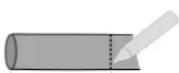
21/32 (17 mm)
25/32 (20 mm)
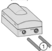
Fig. 39
Insert the hoses Fig.391 into the water filter module as far as they will go (i.e. to the mark you made) past the point of resistance.
Note
If you need to disassemble the unit: Push back the dark grey ring on the connector and hold it in this position. While still holding the ring back, briefly push the hose into the connector, then pull it out.
Insert the power cable into the socket (see 4.10).
Connect appliance to the water supply (see 4.5).
Make sure the filter is leak-tight and no water is coming out.
Place the tray cover Fig.41 (3) into position.
③
Fig. 40
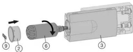
Fig. 41
Remove the film from the water filter Fig. 41 (6).
Insert the water filter Fig. 41 (6) and turn it approximately 100^ to the right until it locks into position.
Place the cover on the filter Fig. 41 (2).
▶ Slide the tray in.
Write the date of the next filter replacement on the supplied adhesive label Fig. 41 (9) and affix it to the module.
Note
New water filters may contain particulate matter.
Do not consume or use ice cubes produced within 72 hours after replacing the filter.
The water filter is now ready for use.
NOTICE
Risk of damage due to leaking water!
- When pushing the appliance into the recess ensure that the water connection does not bend or become damaged.
4.9 Disposal of packaging

WARNING
Danger of suffocation from packaging materials and films!
Do not allow children to play with packaging materials.
The packaging is made from recyclable materials:
Corrugated card/cardboard
- Parts made of foamed polystyrene
- Films and bags from polyethylene
- Packing bands from polypropylene
- Wood frame nailed together with a polyethylene window*
Take the packaging material to an official collection point.

4.10 Connecting the appliance

WARNING
Electrical shock hazard!
Start-up should only take place once the appliance has been installed according to these instructions.
Electrically ground appliance.
Do not ground to a gas pipe.
Check with a qualified electrician if you are not sure the appliance is properly grounded.
Do not have a fuse in the neutral or grounding circuit.
Do not use an extension cord, power bar or a multiple socket adapter.
Do not use a power cord that is frayed or damaged.

WARNING
Electrical shock hazard!
This appliance is equipped with a three-prong (grounding) polarized plug for your protection against possible shock hazards. Electrical Grounding Required.
Do not remove the round grounding prong from the plug.
Use only an grounded adapter.
- Wait 1 hour after installation before you plug in the appliance. This allows the refrigerant and system lubrication to reach equilibrium.
Make sure incoming voltage is the same as the appliance rating. A 110-120 Volt, 60Hz 15 Amp electrical supply (20 Amp for side-by-side installations) circuit that is controlled by a circuit breaker or fuse is required. - We recommend using a dedicated circuit for this appliance to prevent electrical overload.
- Follow all Federal, State and local electrical, fire and building codes and ordinances when installing the receptacle and / or the appliance.
- In some communities, a wall switch is required to turn power to the appliance ON and OFF.
- To reduce the risk of fire, electric shock, or personal injury, installation work and electrical wiring must be done by a qualified electrician in accordance with all applicable codes and standards, including fire-rated construction.
- The Power Plug must be easily accessible so that the appliance can be disconnected from the mains quickly in an emergency. It must not be behind the back of the appliance.
4.11 Switching on the appliance
Note
To switch on the entire appliance, only the freezer compartment needs to be switched on.
Switch on the appliance 2 hours before loading with frozen food for the first time.
Do not load frozen foods until the temperature display reads 0^(-18^)

4.11.1 Switching on the freezer compartment
Press On/Off button, freezer compartment Fig. 4 (13).
The fridge compartment temperature display shows the current temperature in the interior.
The freezer compartment temperature display and the Alarm symbol will flash until the temperature is cold enough. If the temperature is greater than 32^ (0^) , flashing dashes will appear; if the temperature is lower than this, the current temperature will flash on the display.
Whenever "DEMO" appears on the display, the appliance is running in demonstration mode. Contact the customer service department.
4.11.2 Switching on the fridge compartment
Press Fridge compartment On/Off button Fig. 4 (3).
The interior light comes on when the door is opened.
The temperature display flashes. The fridge compartment is switched on.
5 Operation
5.1 Temperature display unit
The temperature display can be changed from ^ F to ^ C .
5.1.1 To change the unit
Activate setting mode: Press SuperFrost button Fig. 4 (14) for about 5 seconds.
5 is displayed in the temperature display.
The Menu symbol Fig. 4 (19) lights up.
Using Freezer compartment Up button Fig.4 (11) Freezer compartment Down button Fig.4 (12) select ^o
To confirm: Briefly press SuperFrost button Fig.4(14).
Using Freezer compartment Up button Fig.4 (11) Freezer compartment Down button Fig.4 (12) select ^ or ^ C
To confirm: Briefly press SuperFrost button Fig.4(14).
To exit setting mode: Press Freezer compartment On/Off button Fig. 4(13).
-or-
Wait 5 minutes.
The temperature is again displayed in the temperature display.
5.2 Brightness of the temperature display
You can adapt the brightness of the temperature display to the light conditions in the room in which it is installed. If the door is open or the control panel is used the temperature indicator lights up at maximum brightness. About 1 minute after the door is closed or no button has been pressed on the control panel, the temperature display goes back to the set brightness.
5.2.1 Setting the brightness
The brightness can be set between h0 (minimum luminosity) and h5 (maximum luminosity).
To activate setting mode: Press SuperFrost button Fig. 4 (14) for about 5 seconds.
S is shown on the display.
The Menu symbol Fig. 4 (19) lights up.
Press Freezer compartment Up button Fig. 4 (11) or Freezer compartment Down button Fig. 4 (12) to select h.
To confirm: Briefly press SuperFrost button Fig. 4 (14).
To set the display brighter: Press Freezer compartment Up button Fig. 4 (11).
To set the display darker: Press Freezer compartment Down button Fig. 4 (12).
To confirm: Press SuperFrost button Fig.4 (14).
The brightness is set to the new value.
To deactivate setting mode: Press Freezer compartment On/Off button Fig. 4 (13).
-or-
Wait 5 minutes.
The temperature is again displayed in the temperature display.
5.3 Child-proof lock
You can use the child-proof lock to lock the buttons. This means that children cannot accidentally switch off the appliance when playing.
5.3.1 Switching on the child-proof lock
Activate setting mode: press and hold the SuperFrost button Fig. 4 (14) for approximately 5 s.
5 is shown on the display.
The Menu symbol Fig. 4 (19) lights up.
Using the Freezer compartment Up button Fig. 4 (11) or Freezer compartment Down button Fig. 4 (12), select e.
Press the SuperFrost button Fig. 4 (14) briefly to confirm.
When c1 is shown on the display:
To switch on the child-proof lock, press the SuperFrost button Fig. 4 (14)briefly.
The Child lock symbol Fig. 4 (16) LED lights up. c flashes on the display.


When c_0 is shown on the display:
To switch off the child-proof lock, press the SuperFrost button Fig. 4 (14) briefly.
The Child safety symbol Fig. 4 (16) LED goes out. c flashes on the display.
Deactivate setting mode: press the Freezer compartment On/Off button Fig. 4 (13).
-or- Wait 5 min.
The temperature is again displayed on the temperature display.
5.4 Door alarm
If the door is open for longer than 180 seconds, the acoustic warning sounds.
The acoustic warning stops automatically when the door is closed.
5.4.1 Switching off the door alarm
The acoustic warning can be switched off when the door is open. The acoustic warning remains switched off as long as the door is open. When the door is closed, the alarm function is active again.
Press Alarm button Fig. 4 (15).
The door alarm stops.
5.5 Temperature alarm
If the freezer temperature is not cold enough, the audible warning sounds.
At the same time, the temperature display and the Alarm symbol Fig. 4 (9) LED will flash.
The cause of a temperature being too high may be:
- Hot fresh food was placed in the appliance.
- When sorting and removing food from the appliance, too much warm ambient air got in.
-
The power was cut off for a while.
-
The appliance is faulty.
The audible warning automatically ceases, the Alarm symbol Fig. 4 (9) goes out, and the temperature display stops flashing when the temperature is cold enough again.
If the alarm status remains: (see Troubleshooting).
Note
If the temperature is not cold enough, food may spoil.
Check the quality of the food. Do not consume spoiled food.
5.5.1 Switching off the temperature alarm
The acoustic warning can be switched off. When the temperature is cold enough again, the alarm function is active again.
Press Alarm button Fig. 4 (15).
The acoustic warning ceases.
5.6 Sabbath Mode
This function meets the religious requirements on the Sabbath and Jewish festivals. When the appliance is in Sabbath mode some control electronic functions are switched off. After setting Sabbath mode you no longer need to worry about indicator lights, figures, symbols, displays, alarm messages and fans. The thawing cycle only operates at the specified time without taking refrigerator use into account. After a power cut the appliance automatically switches on again in Sabbath mode.

WARNING
Danger of food poisoning!
No record will be kept of a power failure during Sabbath Mode. Thus, during Sabbath mode, if a power failure occurs that you are not aware of, when the power comes back on, the unit will continue to be in Sabbath Mode but when Sabbath Mode is ended there will be no indication that a power failure occurred.
If a power failure occurs during Sabbath mode:
Check the quality of the food. Do not consume spoiled food!
- All functions are blocked until Sabbath mode is switched off.
- If the unit is currently running in a mode such as Superfrost, Supercool or the Ventilation is enabled these functions will continue and finish their timed cycles independent of now being in Sabbath mode.
- The Ice Maker is disabled."
- No audible signals are emitted, and the temperature display does not indicate any warnings or settings (such as a temperature alarm or door alarm).
Light does not operate.
5.6.1 Setting Sabbath mode
To activate setting mode: Press and hold the SuperFrost button Fig. 4(14) for approx. 5 s.
5 flashes on the display.
The Menu symbol Fig. 4 (19) lights up.
To access the Sabbath mode function: Briefly press theSuperFrost button Fig. 4 (14).
When SI is shown on the display:
To turn on Sabbath mode, briefly press the SuperFrost button Fig. 4 (14).
When 50 is shown on the display:
To turn off Sabbath mode, briefly press the SuperFrost button Fig. 4 (14).
To deactivate setting mode: Press the Freezer compartment On/Off button Fig. 4 (13).


-or-
Wait 5 min.
The Sabbath Mode symbol Fig. 4 (18) appears on the temperature display as long as Sabbath Mode is active.
Sabbath mode switches off automatically after 120 hours if it is not manually switched off beforehand.
Operation
5.7 Fridge compartment
The natural circulation of air in the refrigerator compartment results in zones with differing temperatures. It is coldest directly above the vegetable drawers and at the rear wall. It is warmest at the top front of the compartment and in the door.
5.7.1 Refrigerating food
Note
Do not load the door with more than 40 lbs (18 kg) of food.
Note
Insufficient ventilation results in an increase in energy consumption and reduction of the refrigerating performance.
Never block the air slits in the fan.
Use recyclable plastic, metal, aluminum and glass containers and cling film to wrap foods.
Always use closed containers for liquids and for food that may give off or be tainted by odor or flavor transfer or cover them.
Foods which give off a large amount of ethylene gas and those that are sensitive to this gas, such as fruit, vegetables and salad, should always be separated or wrapped so as not to reduce the storage life; for example, do not store tomatoes together with kiwi fruits or cabbage.
Do not store food too close together to enable sufficient air circulation.
To ensure bottles do not tip over: move the bottle holder.
5.7.2 Setting the temperature
The temperature depends on the following factors:
- the number of times the door is opened
- the room temperature of the installation location
- the type, temperature and amount of food.
The temperature can be set from 35^ (2^) to 45^ (7^) , 41^ (5^) is recommended.
To set a higher temperature: press the Fridge compartment Up button Fig. 4 (4).
To set a lower temperature: press the Fridge compartment Down button Fig. 4 (5).
When pressed once the previously set fridge compartment temperature display value will flash.
To change the temperature in 1^ (1^) increments: briefly press the button.
To change the temperature continuously: hold the button down.
The value is displayed flashing during the setting operation.
The actual temperature is displayed about 5 seconds after the last press of a button. The temperature slowly adjusts to the new value.
5.7.3 SuperCool
With SuperCool you switch to the highest cooling performance to reach lower cooling temperatures. Use SuperCool to rapidly cool large quantities of food.

If SuperCool is on, the fan* may come on. The appliance works at maximum refrigerating power. The sound of the refrigeration unit may be temporarily louder as a result.
SuperCool will use more energy than normal operation.
Cooling with SuperCool
Briefly press the SuperCool button Fig. 4 (2).
The SuperCool symbol Fig. 4 (6)LED lights up on the display.
The cooling temperature drops to the coldest value. SuperCool is switched on.
SuperCool automatically switches itself off after about 6-12 hours. The appliance returns to work in the energy-saving normal mode.
To prematurely switch off SuperCool
Briefly press the SuperCool button Fig. 4 (2).
The SuperCool symbol Fig. 4 (6) LED goes out on the display.
SuperCool is switched off.
5.7.4 Fan
The fan allows you to rapidly cool large amounts of fresh food or to achieve a relatively even distribution of temperature across all the storage levels.

Re-circulated air cooling is advisable:
- at high room temperatures (from approx. 95^ (35^) )
- in the case of high humidity
Re-circulated air cooling has a somewhat higher energy consumption. To save energy, the fan automatically switches off when the door is open.
Briefly press Ventilation button Fig. 4 (1).
The Ventilation symbol Fig. 4 (17) LED lights up.
The fan is on. On some appliances it only switches on when the compressor is running.
Switching the fan off (default)
Briefly press Ventilation button Fig. 4 (1).
The Ventilation symbol Fig. 4 (17) LED goes out.
The fan is switched off.
5.7.5 Shelves
Shifting or removing shelves

CAUTION
Danger of lacerations!
The storage shelf can shatter if dropped or mishandled. You could cut yourself on the pieces of broken glass.
Only remove storage shelves when there is nothing on them.
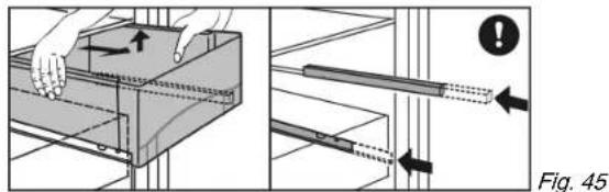
Extension stops secure the shelves against being accidentally pulled out.
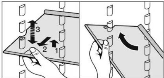
Fig. 42
Lift up the shelf and pull it slightly forward.
Adjust the shelf height by shifting the spacers in the runners.
Insert the short shelf at the height of the gallon capacity rack so that door closes properly. It is supported on support bars.
To remove the shelf completely, set it at an angle and pull it out towards you.
Insert the shelf with the raised edge to the back pointing upwards.
This prevents food from contacting and freezing to the back wall.
The bottle holder offers additional storage for bottles (maximum height 11-13/16" (300 mm)). It fits onto the same supports as the other racks.
Insert the bottle holder into any position, but not right at the bottom.
To dismantle shelves
The shelves can be dismantled for cleaning.
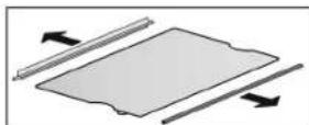
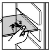
5.7.6 Using the split shelf

CAUTION
Danger of lacerations!
The storage shelf can shatter if dropped or mishandled. You could cut yourself on the pieces of broken glass.
Only remove storage shelves when there is nothing on them.
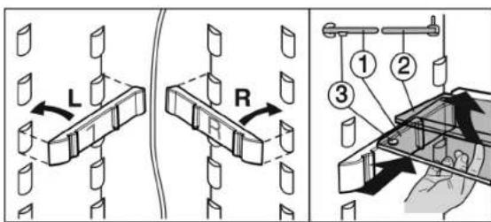
Fig. 43
Attach support bars supplied, ensuring right (R) and left (L) parts are correctly positioned.
The glass shelf with stop face (2) has to be at the back.
5.7.7 Door racks
Note
Do not load the door with more than 40 lbs (18 kg) of food.
Repositioning the door racks
Push rack up, pull forward, and reinsert in the reverse order.
The container trays can be removed and placed on the table as a unit.
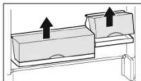
Instead of one wide container and one small container, a special set containing three small containers is available from Customer Service.
It is possible to use one or both boxes. If unusually tall bottles are to be stored, only suspend one box above the bottle rack.
To swap containers: pull up to remove and reinsert in the desired position.
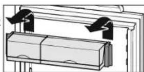
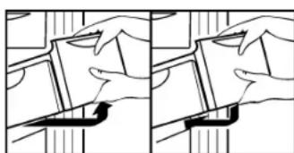
To dismantle door racks
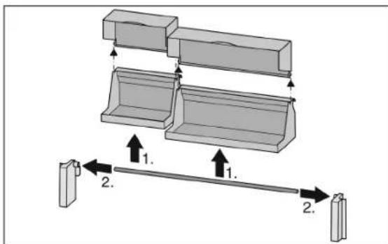
Fig. 44
The door racks can be dismantled for cleaning.
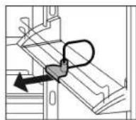
5.7.8 Removing the bottle holder
Always take hold of the bottle holder by the plastic part.
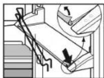
5.7.9 Vegetable drawers
To remove the vegetable drawers:
Pull the vegetable drawer completely out and tilt it slightly forward.
Push the protruding telescopic rails back in.

To insert the vegetable drawers:
Place the vegetable drawer on the telescopic rails and slide it back while applying light pressure.
5.8 Freezer compartment
You can store frozen food, make ice cubes and freeze fresh food in the freezer compartment.
5.8.1 Freezing food
Each drawer can hold up to 55.12 lbs (25 kg) of frozen food; each plate can hold up to 77.16 lbs (35 kg).

CAUTION
There is a risk of injury from pieces of broken glass. Bottles and cans containing drinks can split or crack when frozen. This applies in particular to carbonated drinks.
Do not freeze bottles and cans containing drinks.
So that the food is rapidly frozen through to the core, do not exceed the following quantities per pack:
- fruit, vegetables up to 2.2 lb (1 kg)
- meat up to 5.51 lbs (2.5 kg)
Pack the food in portions in freezer bags, reusable plastic, metal or aluminum containers.
5.8.2 Defrosting food
- in the fridge compartment
- in the microwave
- in the oven/fan oven
- at room temperature

WARNING
Danger of food poisoning!
Do not re-freeze defrosted food.
Only take out the amount of food that is required. Use defrosted food as quickly as possible.
5.8.3 Setting the temperature in the freezer compartment
The appliance is set as standard for normal operation.
The temperature can be set between 7^ (-14^) and -16^ (-26^) , 0^ (-18^) is recommended.
To set a higher temperature: press the Freezer compartment Up button Fig. 4 (11).
To set a lower temperature: press the Freezer compartment Down button Fig. 4 (12).
When the button is pressed for the first time, the previous value is indicated on the freezer compartment temperature display.
To change the temperature in 1^ (1^) increments: briefly press the button.
-or-
To change the temperature continuously: hold the button down.
The value is displayed flashing during the setting operation.
The actual temperature is displayed about 5 seconds after the last press of a button. The temperature slowly adjusts to the new setting.
5.8.4 SuperFrost
Depending on how much fresh food is to be frozen you must switch SuperFrost on in advance - for a small amount of food to be frozen, about 6 hours, for the maximum amount about 24 hours before putting the food in.
You do not need to switch SuperFrost on in the following cases:
- when placing frozen food in the freezer
- when freezing up to about 2kg of fresh food a day
Freezing with SuperFrost
Briefly press the SuperFrost button Fig. 4 (14) once.
The SuperFrost symbol Fig. 4 (21)LED lights up.
The freezing temperature drops and the appliance operates at its maximum refrigeration power rating. When a small amount of food is to be frozen.
Wait approx. 6 hrs.
Place packaged food in the upper drawers. When the maximum amount of food is to be frozen.
Wait approx. 24 hrs.
Remove upper drawers and place the food directly onto the upper shelves.
SuperFrost is automatically switched off. At the earliest after 30 hours, at the latest after 65 hours, depending on the quantity placed inside the appliance.
The LED for the SuperFrost symbol Fig.4 (21) goes out when the freezing process is complete.
Place food inside the drawers and push them closed again.
The appliance returns to work in the energy-saving normal mode.
5.8.5 Drawers
Note
Insufficient ventilation results in an increase in energy consumption and reduction of the refrigerating performance.
For appliances with NoFrost:
Leave the bottom drawer in the appliance.
Never block the air slits in the fan on the rear wall.
To store frozen food directly on the shelves: pull the drawer forward and lift it out.
5.8.6 Shelves
To remove shelf: lift it at the front and pull out forward.
To reinsert shelf: simply slide it in as far as it will go.
5.8.7 VarioSpace
In addition to the drawers, you can also take out the shelves. This gives you space for large frozen items. Poultry, meat, large joints of game and tall bakery items can be frozen and then presented whole.
Each drawer can hold up to 55.12 lbs (25 kg) of frozen food; each plate can hold up to 77.16 lbs (35 kg).

5.8.8 Info system
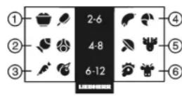
(1) Ready meals, ice cream
(2) Pork, fish (5) Game, mushrooms
(3) Fruit, vegetables (6) Poultry, beef/veal
Fig. 47
The numbers indicate the storage time in months for different types of frozen foods. The storage times given are guidelines.
5.8.9 IceMaker*
The IceMaker is in the top drawer. The drawer is labeled "IceMaker".
Make sure that the following conditions are fulfilled:
The appliance is level.
- The appliance is connected to the electricity supply.
- The freezer compartment is switched on.
The minimum freezer temperature is 14^ (-10^)
- The IceMaker is connected to the water supply.
- All air was bled from the waterline before starting the icemaker. The icemaker will only work if there is no air in the waterline.
Maintenance
Switching on the IceMaker*
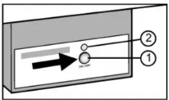
Fig. 48
▶ Pull out the drawer.
Press On/Off button Fig. 48 (1) so that the LED Fig. 48 (2) lights up.
▶ Push in the drawer.
The IceMaker symbol Fig. 4 (10) LED lights up.
Note
The IceMaker only produces ice cubes when the drawer is completely closed.
Producing ice cubes*
The production capacity depends on the freezer temperature. The lower the temperature, the more ice cubes can be produced in a certain period.
The production capacity is 90-100 ice cubes in 24 hours at a freezing temperature of 0^ (-18^)
To have the maximum capacity of approx. 130 ice cubes in 24 hours, activate the SuperFrost Function. Be aware that this increases the energy consumption because the compressor will run constantly.
The ice cubes fall out of the IceMaker into the drawer. When the ice cubes reach a certain height in the drawer, no more ice cubes can be produced. The IceMaker will not fill the drawer to the top.
If large quantities of ice cubes are required, the complete IceMaker drawer can be swapped with the neighboring drawer. When you close the drawer, the IceMaker automatically restarts production.
When the IceMaker is switched on for the first time, it may take up to 24 hours for the first ice cubes to be produced.
Note
Particles may accumulate in the IceMaker or water line the first time the appliance is used or after an extended period out of service.
To achieve this, do not consume or use the ice cubes that are produced within 72 hours.
Setting the water supply time*
The opening time of the valve on the IceMaker can be adjusted if, for example, the water pressure in the pipe is too low or too high.
The water supply time can be set in stages from E1 (short supply time) to E8 (long supply time). The default setting is E3.
Activate setting mode: press and hold the SuperFrost button Fig. 4 (14) for approximately 5 s.
5 is shown on the display.
The Menu symbol Fig. 4 (19) lights up.
Using the Freezer compartment Up button Fig. 4 (11) or Freezer compartment Down button Fig. 4 (12), select E.
To confirm: briefly press the SuperFrost button Fig.4 (14).
To increase the water supply time: press the Freezer compartment Up button Fig. 4 (11).
To decrease the water supply time: press the Freezer compartment Down button Fig. 4 (12).
To confirm: press the SuperFrost button Fig.4(14).
Deactivate setting mode: press the Freezer compartment On/Off button Fig. 4 (13).
-or- Wait 5 mins.
The temperature is again displayed on the temperature display.
Switching off the IceMaker*
If ice cubes are not required, the IceMaker can be switched off independently of the freezer compartment.
When the IceMaker is switched off, the drawer of the IceMaker can also be used for freezing and storing food.
Press the On/Off button for about 1 second until the LED goes out.
The IceMaker symbol Fig. 4 (10)LED goes out.
Clean the IceMaker
This ensures that no water or ice remains in the IceMaker.
6 Maintenance
6.1 Replacing the water filter*
When used as indicated, the water filter should be replaced at least every 6 months or whenever you notice a considerable decrease in the flow rate.
Your nearest dealer can be located by visiting us online at www.Liebherr.com.
The used water filter contains activated carbon and can be disposed of with normal household waste.
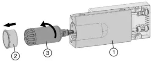
Fig. 49
To remove the old water filter:
Pull out the tray Fig. 49 (1), if necessary.
Remove the filter cover Fig. 49 (2).
Turn the water filter Fig. 49 (3) approximately 100^ counterclockwise and pull it out.
Catch any dripping water with your hand, towel or with a dish.
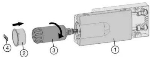
Fig. 50
To install a new water filter:
Insert the water filter Fig. 50 (3) and turn it approximately 100^ clockwise until it locks into position.
▶ Slide the tray Fig. 50 (1) in.
Place the cover Fig. 50 (2) on the filter.
Write the date of the next filter replacement on the supplied adhesive label Fig. 50 (4) and affix it to the module.
Note
New water filters may contain particulate matter.
Do not consume or use ice cubes produced within 72 hours after replacing the filter.
- Remove any ice still present in the IceMaker tray. You can keep this ice in another tray for later use.
Make sure the filter is leak-tight and no water is coming out.
6.2 Defrosting with NoFrost
The NoFrost system defrosts the appliance automatically.
Fridge compartment:
The defrosted water is evaporated by the heat of the compressor. Drops of water on the back wall are a functional feature and completely normal.
Clean the drain opening regularly so that the defrosted water can flow away (see 6.3).
Freezer compartment:
The moisture condenses on the evaporator and is periodically defrosted and evaporated.
The appliance does not need to be defrosted manually.
6.3 Cleaning the appliance

WARNING
Danger of electric shock.
Unplug refrigerator or disconnect power.

WARNING
Risk of injury or damage due to hot steam. Hot steam can cause scalding/burns and damage to surfaces.
Do not use steam cleaners.
NOTICE
Incorrect cleaning damages the appliance.
Do not use concentrated cleaning agents.
Do not use steel wool or sponges that scour or scratch.
Do not use caustic or abrasive cleaning materials or those containing sand, chloride, chemicals or acids.
Do not use chemical solvents.
Do not damage or remove the rating plate on the inside of the appliance. It is vital for the customer service department.
Do not pull off, kink or damage any cables or other components.
Do not let cleaning water get into the drain gutter, the ventilation grille and electrical parts.
Use soft cleaning cloths and a multi-purpose cleaning agent with a neutral pH value.
Only use food-compatible cleaning and care agents inside the appliance.
Empty the appliance.
Disconnect the power plug.

Clean the plastic surfaces, outside and inside, by hand using lukewarm water and a little dish washing liquid.
Stainless steel which is exposed to chlorine gas or dampness may become discolored. This is normal. If your appliance is exposed to chlorine gas or dampness, clean and polish it more frequently. If there are any signs of rust or discoloration, clean and polish the appliance as soon as possible.
Do not apply stainless steel cleaning agents to glass or plastic surfaces so as not to scratch them. Initially darker areas and quite an intensive color of the stainless steel surfaces are normal.
NOTICE
The stainless steel doors are treated with a high-grade surface coating and must not be cleaned with the supplied cleaning agent.

This would damage the surface coating.
Wipe the coated door surfaces using a soft, clean cloth only. In case of stubborn dirt, use a little water or a neutral cleaning agent. A microfibre cloth can be optionally used.
If the stainless steel side walls are dirty, clean them using a commercially available stainless steel cleaning agent. Then evenly apply the accompanying stainless steel care product, making strokes in the direction of the grain.
Wipe side walls with a paint finish using a soft, clean cloth only. In case of stubborn dirt, use a little water or a neutral cleaning agent. A microfibre cloth can be optionally used.
Troubleshooting.
To clean the drain opening: Remove deposits with a thin instrument, e.g. a cotton bud.
Most of the equipment parts can be dismantled for cleaning: see the respective chapter.
Clean fittings by hand using lukewarm water and a little dish washing liquid.
Clean the telescopic rails with a damp cloth only. The grease in the tracks is for lubrication purposes and should not be removed.
After cleaning:
Wipe the appliance and accessories dry.
Connect the appliance and switch it on again.
Switch on SuperFrost (see 5.8.4)
When the temperature is sufficiently cold:
put the food back in the appliance.
6.4 Cleaning the IceMaker*
The IceMaker drawer must be emptied and pushed in.
Activate setting mode: press and hold the SuperFrost button Fig. 4 (14) for approximately 5 s.
5 is shown on the display.
The Menu symbol Fig. 4 (19) lights up.
Using the Freezer compartment Up button Fig. 4 (11) Freezer compartment Down button Fig. 4 (12), select I.
To confirm: press the SuperFrost button Fig. 4 (14).
Using the Freezer compartment Up button Fig.4(11)/Freezer compartment Down button Fig.4(12),select ic.
To confirm: press the SuperFrost button Fig.414
The IceMaker moves into cleaning position and shuts off.
Deactivate setting mode: press the Freezer compartment On/Off button Fig. 4 (13).
-or-
Wait 2 min.
The temperature is again displayed on the temperature display.
Take out the drawer.
Clean the ice compartment and drawer with warm water. If necessary, use a mild dishwashing liquid. Then rinse.
▶ Slide the drawer back in.
If dishwashing liquid was used:
- Throw out the first three batches of ice cubes to get rid of any dishwashing liquid residues.
Either leave the IceMaker switched off in this position or switch the IceMaker back on (see 5.8.9).
6.5 Customer service
First check whether you can remedy the fault yourself (see Troubleshooting). If this is not the case, please contact a qualified service provider.

WARNING
Risk of injury from repairs by non-professionals.
Repairs and work on the appliance and the power supply cable not described in the Manual (see Maintenance) should only be carried out by a qualified service provider.
Read the appliance designation
Fig. 51 (1), service no.
Fig. 51 (2) and serial no. Fig. 51 (3) from the rating plate. The rating plate is located inside the appliance on the left-hand side.
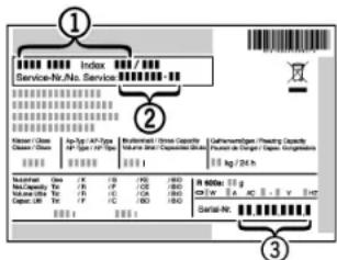
Fig. 51
- Notify a qualified service provider, specifying the fault, appliance designation Fig. 51 (1), service no. Fig. 51 (2) and serial Fig. 51 (3) no.
This will help us to provide you with a faster and more accurate service. - Keep the appliance closed until the Customer Service engineer arrives.
The food will stay cool longer.
Disconnect the power plug (do not pull on the power cord to do this) or switch off the fuse.
6.6 Appliance Information
Make a note of this information when the appliance is installed:
Type Designation:
Service Number:
Appliance / Serial Number:
Date of purchase:
Where purchased:
7 Troubleshooting.
Your appliance is designed and manufactured for reliable operation and a long lifespan. If a malfunction nonetheless occurs during operation, please determine if the malfunction is due to an operating error. If a service call determines operator error, you will be charged for the costs incurred, even during the warranty period. You may be able to rectify the following problems yourself:
| Problem Possible | Cause Correction | |
| The appliance does not work. | The appliance is not switched on. | Switch on the appliance. |
| The power plug is not properly inserted in the wall socket. | Check the power plug. | |
| The fuse in the wall socket is not OK. | Check the fuse. | |
| Power failure | Keep the appliance closed. Protect the food: place dry ice on top of the food or use an alternate freezer, if the power failure persists for some time. Do not re-freeze defrosted food. | |
| The compressor runs for a long time. | When less refrigeration is required, the speed-controlled compressor switches to a low speed. Although the running time is increased as a result, energy is saved. | This is normal in energy-saving models. |
| SuperFrost function is activated. | The compressor runs long to rapidly freeze food. This is normal. | |
| SuperCool function is activated. | The compressor runs long to rapidly cool food. This is normal. | |
| A LED at the lower rear of the appliance (for the compressor) flashes regularly every 15 seconds*. | The inverter is equipped with a diag-nostic LED. | The flashing is normal. |
| Noises are too loud. | The different speed levels of speed-controlled* compressors can cause them to generate various noises during operation. | These noises are normal. |
| A gurgling sound | This sound comes from the refrigerant flowing in the refrigeration circuit. | The sound is normal. |
| A faint clicking sound | The sound always occurs when the refrigeration unit (the motor) automatically switches on or off. | The sound is normal. |
| A hum. It is briefly a little louder when the refrigeration unit (the motor) switches on. | The refrigeration increases automat-ally when the SuperFrost function is activated, fresh food has just been placed in the appliance or the door has been left open for a while. | The sound is normal. |
| The refrigeration increases automat-ally when the SuperCool function is activated, fresh food has just been placed in the appliance or the door has been left open for a while. | The sound is normal. | |
| The ambient temperature is too high. | Solution: (see 1.3) | |
| A low hum | The sound occurs as a result of fan air flow. | The sound is normal. |
| Vibration noise | The appliance is not standing firmly on the floor. As a result, adjoining units or objects are set into vibration by the running refrigeration unit | Align the appliance using the adjustable feet Move bottles and containers apart. |
| The temperature display indicates: F0 to F9. | There is a fault. | Contact the customer service department (see Maintenance). |
| The temperature display reads: FE* | There is a fault. | Contact the customer service department (see Maintenance). |
| The temperature display shows a flashing power failure symbol ∅. The warmest temper- ature reached during the power failure is displayed in the temperature display. | The freezer temperature rose too high during the last hours or days due to power failure or power inter- ruption. When the power interruption is over, the appliance will continue to operate at the last temperature setting. | To delete the display of the warmest temperature: Press the Alarm button Fig. 4(15). Check the quality of the food. Do not consume spoiled food. Do not re-freeze defrosted food. |
| The outside surfaces of the appliance are hot*. | The heat of the refrigerant circuit is used to prevent condensate from forming. | This is normal. |
| The IceMaker cannot be switched on.* | The appliance and therefore the IceMaker are not connected. | Connect the appliance (see Start-up). |
| The IceMaker is not making ice cubes.* | The IceMaker is not switched on. | Switch the IceMaker on. |
| The drawer of the IceMaker is not properly closed. | Close the drawer properly. | |
| The water connection is not open. | Open the water connection. | |
| The water supply to the IceMaker was interrupted. | Check the connection to the water supply (see Start-up).* Check the pipes and hoses (see Start-up).* | |
| There is a blocked filter at the end of the water supply hose or at the connecting part on the machine. | Clean the filters. | |
| The waterline was not bled of all air during installation | Please contact your qualified installation plumber to ensure the above criteria is met before calling for service. | |
| The door of the appliance is not closed properly. | Close the appliance door. | |
| The temperature is not cold enough. | Insufficient ventilation. | \( \blacktriangleright \) Clear ventilation grilles. |
| The ambient temperature is too high. | \( \blacktriangleright \) Solution: (see 1.3) | |
| The appliance was opened too frequently or for too long. | \( \blacktriangleright \) Wait to see whether the required temperature resets itself by itself. If not, contact the customer service department (see Maintenance). | |
| Too much fresh food was placed inside without SuperFrost. | \( \blacktriangleright \) Solution: (see 5.8.4) | |
| The temperature is incorrectly set. | \( \blacktriangleright \) Set to a colder temperature and check after 24 hours | |
| The appliance is too near to a heat source (stove, heater etc). | \( \blacktriangleright \) Change location of appliance or the heat source. | |
| Display show two dashes ("-"). | The freezer temperature display will only show temperatures that are below freezing. | \( \blacktriangleright \) When initially starting the appliance it will not be below freezing. It will take three to five hours (depending on ambient conditions) for freezing temperatures to be achieved and thus displayed numerically. |
| The freezer temperature has risen above zero degrees due to a power failure or power interruption. | \( \blacktriangleright \) See also "Power failure" and "D" | |
| The interior light is not on. | The appliance is not switched on. | \( \blacktriangleright \) Switch on the appliance. |
| The door was open for longer than 15 minutes. | \( \blacktriangleright \) The interior light automatically switches itself off if the door has been open for about 15 minutes. | |
| The LED interior light is faulty or the cover is damaged | \( \blacktriangleright \)WARNINGRisk of injury from electrical shock.Live parts are under the cover.\( \blacktriangleright \) The LED interior light should only be replaced or repaired by the Customer Service department or by engineers trained to do so.\( \blacktriangleright \)WARNINGRisk of injury from LED lamp!The lighting intensity of the LED light complies with laser class 1/1M.If the cover is faulty:\( \blacktriangleright \) Do not gaze directly at this lighting unit with optical lenses while very close to the light source. This can cause damage to your eyes. |
8 Putting appliance out of service
8.1 Vacation Tips
Short vacations: If you will be away for less than four weeks
Use all perishables.
Freeze other items.
Turn off the refrigerator compartment.
Turn off the icemaker.
Shut down the water supply to the icemaker.*
Long vacations: If you will be away for a month or more
Remove all food from the appliance.
Turn OFF the appliance.
Clean the appliance (see 6.3).
Leave the door open to prevent unpleasant odors.
This will also keep mold from building up.
Turn off the icemaker.*
Shut off the water supply to the icemaker.*
8.2 Switching off the appliance
Note
To switch off the entire appliance, only the freezer compartment needs to be switched off.
8.2.1 Switching off the freezer compartment
Press and hold down the freezer compartment On/Off button Fig. 4 (13) for approx. 2 seconds.
The temperature displays are dark. The appliance is switched off.
8.2.2 Switching off the fridge compartment
Press and hold down the chiller compartment On/Off button Fig. 4 (3) for approx. 2 seconds.
The fridge compartment temperature display Fig. 4 (8) is dark. The fridge compartment is switched off.
8.3 Decommissioning *
Empty the appliance.
Put the IceMaker in the cleaning position (see Maintenance).
Disconnect the power plug.
Clean the appliance (see 6.3).
Leave the door open to prevent bad smells.

9 Disposing of the appliance
Follow the local regulations for the disposal of appliances. Old appliances can be dangerous. Contact the local refuse collection department for additional information.

DANGER
There is a risk of suffocation.
Children playing can shut themselves in and suffocate.
Take the door(s) off.
Remove the drawers.
Leave the storage shelves in the appliance so that children cannot easily climb into the appliance.

WARNING
Danger of electric shock.
Cut off the plug from the power cord and discard.
Cut off the power cord from the discarded appliance. Dispose of separately from the appliance.
Ensure during and after disposal that the appliance isn't stored in the vicinity of gasoline or other flammable vapors and liquids.
When disposing of the appliance, ensure that the refrigeration circuit is not damaged to prevent uncontrolled escape of the refrigerant it contains (data on type plate) and oil.
10 Liebherr Warranty Plan
FULL TWO YEAR WARRANTY - For two years from the date of original purchase, your Liebherr warranty covers all parts and labor to repair or replace any part of the product which proves to be defective in materials or workmanship.
FULL FIVE YEAR WARRANTY - For five years from the date of original purchase, your Liebherr warranty covers all parts and labor to repair or replace any components that prove to be defective in materials or workmanship in the sealed system. The "Sealed System" means only the compressor, condenser, evaporator, drier and all connecting tubing.
LIMITED 6TH THROUGH 12TH YEAR WARRANTY - From the 6^th through 12^th year from the date of original purchase, your Liebherr warranty covers all parts that prove to be defective in materials or workmanship in the Sealed System (parts only).
TERMS APPLICABLE TO EACH WARRANTY
All service provided by Liebherr under the warranty must be performed by authorized Liebherr service representatives, unless otherwise specified by Liebherr. Service will be provided in the home during normal business hours. This warranty applies only to products installed for normal residential use. Details regarding a non-residential warranty are available on request.
The warranty applies only to products installed in any one of the fifty states of the United States or the District of Columbia. The warranty does not cover any parts or labor to correct any defect caused by negligence, accident or improper use, maintenance, installation, service or repair, including but not limited to improper removal and reinstallation of the condensing unit.
THE WARRANTY DESCRIBED ABOVE ARE MADE EXPRESSLY IN LIEU OF ANY OTHER WARRANTYES, EXPRESSED OR IMPLIED, INCLUDING ANY IMPLIED WARRANTY OF MERCHANTABILITY OR FITNESS FOR A PARTICULAR PURPOSE, AND OF ANY OTHER OBLIGATION OR LIABILITY ON THE PART OF LIEBHERR. IN NO EVENT SHALL LIEBHERR BE LIABLE FOR SPECIAL, INCIDENTAL OR CONSEQUENTIAL DAMAGES ASING FROM THE BREACH OF THESE WARRANTYES OR ANY OTHER WARRANTYES, WHETHER EXPRESS, IMPLIED OR STATUTORY.
Some states do not allow the exclusion or limitation of incidental or consequential damages so the above limitation or exclusion may not apply to you. This warranty gives you specific legal rights and you may also have other legal rights which vary from state to state.
To receive parts and/or service and the name of the Lieb-herr authorized service representative nearest you,
contact your Liebherr dealer or distributor or contact the
Lieb Herr designated national service provider:
in the US: Service-appiances.us@liebherr.com or call
1-866-LIEBHER (1-866-543-2437).
in Canada: www.euro-parts.ca or call 1-888-LIEBHER
(1-888-543-2437).
LIEBHERR
Mode d'emploi
(C) 1-3/16pcs x 3/8pcs (30mm x 10mm)
(B) 3-15/16pcs (100mm)
(C) 1-3/16 pulp. x 3/8 pulp. (30 mm x 10 mm)
(D) min. 4 pulp (100mm)
This page intentionally left blank.
For Service in the U.S.:
Lieb Herr Service Center
Toll Free: 1-866-LIEBHER or 1-866-543-2437
Service-appiances.us@lieb Herr.com
PlusOne Solutions, Inc.
3501 Quadrangle Blvd, Suite 120
Orlando, FL 32817
For Service in Canada:
Liebherr Service Center
Toll Free: 1-888-LIEBHER or 1-888-543-2437
www.euro-parts.ca
EURO-PARTS CANADA
39822 Belgrave Road
Belgrave, Ontario, N0G 1E0
Phone: (519) 357-3320
Fax: (519) 357-1326