A5012 - Receiver TOA - Free user manual and instructions
Find the device manual for free A5012 TOA in PDF.

| Product | Receiver |
| Brand | TOA |
| Model | A5012 |
| Device type | Class A digital (complies with NMB-003 Canada) |
| Power supply | Mains with earth ground, voltage specified on charger |
| Installation | Indoor only, stable and flat surface |
| Rack mounting | Possible (mounting screws not supplied) |
| Usage | Set volume to minimum before powering on |
| Protection | Do not obstruct ventilation slots |
| Cleaning | Dry cloth only, unplug before cleaning |
| Outlet maintenance | Regularly dust the plug and power outlet |
| Safety | Unplug during thunderstorms and when not in use for extended periods |
| Maintenance | Reserved for qualified technician |
| Environment | Avoid humidity, dust, direct sunlight, heat sources |
| Accessories | Rack mounting screws not included |
| Power cord | Do not damage, do not place heavy objects on it |
| Plug | Polarized or with earth ground |
| Risks | Do not expose to water or liquids |
| Malfunction | Turn off power and contact TOA representative in case of smell, smoke, drop, etc. |
| Prolonged use | Avoid if sound is distorted to prevent speaker overheating |
Frequently Asked Questions - A5012 TOA
User questions about A5012 TOA
0 question about this device. Answer the ones you know or ask your own.
Ask a new question about this device
Download the instructions for your Receiver in PDF format for free! Find your manual A5012 - TOA and take your electronic device back in hand. On this page are published all the documents necessary for the use of your device. A5012 by TOA.
USER MANUAL A5012 TOA
natural_image
Line drawing of a rectangular electronic device with ports and ventilation slots (no text or symbols)TABLE OF CONTENTS
- IMPORTANT SAFETY INSTRUCTIONS ...... 3
- SAFETY PRECAUTIONS 4
- GENERAL DESCRIPTION 8
- FEATURES 8
- HANDLING PRECAUTIONS 8
- INSTALLATION PRECAUTIONS 8
- NOMENCLATURE AND FUNCTIONS ...... 9
Front 9
Rear 10
Left Side 11
- CONNECTION EXAMPLES ...... 12
- CONNECTION 13
9.1. Removable Terminal Plug Connection 13
9.2. How to Connect Input Signals 14
9.3. Speaker Output Signal Connections 15
9.4. Remote Control Equipment Connections 16
9.5. Connection to PCs 16
- RACK-MOUNTING THE MIXER AMPLIFIER 17
- BLOCK DIAGRAM 20
- DIMENSIONAL DIAGRAM 21
- SPECIFICATIONS 22
Accessories 22
Optional products 22
1. IMPORTANT SAFETY INSTRUCTIONS
- Read these instructions.
- Keep these instructions.
- Heed all warnings.
- Follow all instructions.
- Do not use this apparatus near water.
- Clean only with dry cloth.
- Do not block any ventilation openings. Install in accordance with the manufacturer's instructions.
- Do not install near any heat sources such as radiators, heat registers, stoves, or other apparatus (including amplifiers) that produce heat.
- Do not defeat the safety purpose of the polarized or grounding-type plug. A polarized plug has two blades with one wider than the other. A grounding type plug has two blades and a third grounding prong. The wide blade or the third prong are provided for your safety. If the provided plug does not fit into your outlet, consult an electrician for replacement of the obsolete outlet.

- Protect the power cord from being walked on or pinched particularly at plugs, convenience receptacles, and the point where they exit from the apparatus.
- Only use attachments/accessories specified by the manufacturer.
- Use only with the cart, stand, tripod, bracket, or table specified by the manufacturer, or sold with the apparatus. When a cart is used, use caution when moving the cart/apparatus combination to avoid injury from tip-over.
- Unplug this apparatus during lightning storms or when unused for long periods of time.
- Refer all servicing to qualified service personnel. Servicing is required when the apparatus has been damaged in any way, such as power-supply cord or plug is damaged, liquid has been spilled or objects have fallen into the apparatus, the apparatus has been exposed to rain or moisture, does not operate normally, or has been dropped.
INSTRUCTIONS ESSENTIELLES POUR LA SÉCURITÉ
- Before installation or use, be sure to carefully read all the instructions in this section for correct and safe operation.
- Be sure to follow all the precautionary instructions in this section, which contain important warnings and/or cautions regarding safety.
• After reading, keep this manual handy for future reference.
Safety Symbol and Message Conventions
Safety symbols and messages described below are used in this manual to prevent bodily injury and property damage which could result from mishandling. Before operating your product, read this manual first and understand the safety symbols and messages so you are thoroughly aware of the potential safety hazards.

WARNING
Indicates a potentially hazardous situation which, if mishandled, could result in death or serious personal injury.

CAUTION
Indicates a potentially hazardous situation which, if mishandled, could result in moderate or minor personal injury, and/or property damage.

WARNING
When Installing the Unit
- The apparatus shall be connected to a MAINS socket outlet with a protective earthing connection.
- Do not expose the unit to rain or an environment where it may be splashed by water or other liquids, as doing so may result in fire or electric shock.
- Use the unit only with the voltage specified on the unit. Using a voltage higher than that which is specified may result in fire or electric shock.
- Do not cut, kink, otherwise damage nor modify the power supply cord. In addition, avoid using the power cord in close proximity to heaters, and never place heavy objects -- including the unit itself -- on the power cord, as doing so may result in fire or electric shock.
- Avoid installing or mounting the unit in unstable locations, such as on a rickety table or a slanted surface. Doing so may result in the unit falling down and causing personal injury and/or property damage.
- Since the unit is designed for indoor use, do not install it outdoors. If installed outdoors, the aging of parts causes the unit to fall off, resulting in personal injury. Also, when it gets wet with rain, there is a danger of electric shock.
When the Unit is in Use
- Should the following irregularity be found during use, immediately switch off the power, disconnect the power supply plug from the AC outlet and contact your nearest TOA dealer. Make no further attempt to operate the unit in this condition as this may cause fire or electric shock.
- If you detect smoke or a strange smell coming from the unit.
- If water or any metallic object gets into the unit
- If the unit falls, or the unit case breaks
- If the power supply cord is damaged (exposure of the core, disconnection, etc.)
- If it is malfunctioning (no tone sounds.)
- To prevent a fire or electric shock, never open nor remove the unit case as there are high voltage components inside the unit. Refer all servicing to qualified service personnel.
- Do not place cups, bowls, or other containers of liquid or metallic objects on top of the unit. If they accidentally spill into the unit, this may cause a fire or electric shock.
- Do not insert nor drop metallic objects or flammable materials in the ventilation slots of the unit's cover, as this may result in fire or electric shock.
- Do not touch a power supply plug during thunder and lightning, as this may result in electric shock.

CAUTION
When Installing the Unit
- Never plug in nor remove the power supply plug with wet hands, as doing so may cause electric shock.
- When unplugging the power supply cord, be sure to grasp the power supply plug; never pull on the cord itself. Operating the unit with a damaged power supply cord may cause a fire or electric shock.
- When moving the unit, be sure to remove its power supply cord from the wall outlet. Moving the unit with the power cord connected to the outlet may cause damage to the power cord, resulting in fire or electric shock. When removing the power cord, be sure to hold its plug to pull.
- Do not block the ventilation slots in the unit's cover. Doing so may cause heat to build up inside the unit and result in fire. Also, periodically clean the ventilation slots of dust.
- Avoid installing the unit in humid or dusty locations, in locations exposed to the direct sunlight, near the heaters, or in locations generating sooty smoke or steam as doing otherwise may result in fire or electric shock.
-
To avoid electric shocks, be sure to switch off the unit's power when connecting speakers.
-
Be sure to follow the instructions below when rack-mounting the unit. Failure to do so may cause a fire or personal injury.
- Install the equipment rack on a stable, hard floor. Fix it with anchor bolts or take other arrangements to prevent it from falling down.
- When connecting the unit's power cord to an AC outlet, use the AC outlet with current capacity allowable to the unit.
- Rack-mounting screws are not supplied with the unit. Prepare them that are appropriate for the equipment rack.
When the Unit is in Use
- Make sure that the volume control is set to minimum position before power is switched on. Loud noise produced at high volume when power is switched on can impair hearing.
- Do not operate the unit for an extended period of time with the sound distorting. Doing so may cause the connected speakers to heat, resulting in a fire.
- Contact your TOA dealer as to the cleaning. If dust is allowed to accumulate in the unit over a long period of time, a fire or damage to the unit may result.
- If dust accumulates on the power supply plug or in the wall AC outlet, a fire may result. Clean it periodically. In addition, insert the plug in the wall outlet securely.
- Switch off the power, and unplug the power supply plug from the AC outlet for safety purposes when cleaning or leaving the unit unused for 10 days or more. Doing otherwise may cause a fire or electric shock.
CONSEILS DE SÉCURITÉ
The A-5006/5012 is a compact desktop integrated Mixer Amplifier with a 4-input/1-output configuration. The 4 inputs include an assortment of line and microphone inputs. The unit is equipped with a terminal that allows remote control of overall sound volume. Signal processing, including equalization and compression, can be performed using the supplied A-5000 PC Software.*
The unit can also be easily mounted in an EIA-standard equipment rack with the additional purchase of optional rack mounting hardware. Horizontal connectivity permits two mixer amplifiers to be simultaneously mounted in a one-unit size rack space.
* Recorded on the supplied CD.
4. FEATURES
- The input sensitivity of Inputs 1 and 2, and impedance of the speaker outputs are set by way of a DIP switch located on the unit's rear panel.
- The input sensitivity of Inputs 1 and 2 can be independently set to either MIC or LINE signal level. Inputs 3 and 4 are fixed at LINE level.
- Speaker outputs can be set for either low or high impedance connections.
- A manual muting function and a remote master volume control function allow remote adjustment of the sound volume.
- The unit is equipped with the LAN port, making it possible to perform the unit's settings using the A-5000 PC Software. Functions that can be set include an input equalizer, output equalizer, compressor and master volume.
5. HANDLING PRECAUTIONS
- The supplied power cord is designed to be used exclusively with the unit. Do not connect it to any other equipment.
- Install the unit in locations where the temperature is between 0 and 40^ (32 and 104^ ) and the moisture is between 35 and 80% (no dew condensation must be formed).
- The unit is a precision audio component. To prevent failure, avoid locations where the unit may be exposed to strong shocks or vibrations.
- To clean, be sure to first switch off the unit's power, then wipe with a dry cloth. Never use benzene, thinner, alcohol, or chemically-treated cleaning cloth because such volatile liquids could deform or discolor the unit.
6. INSTALLATION PRECAUTIONS
- Be sure to install and connect the unit before the connection to the AC mains outlet. Remove the unit's power supply cord from the AC mains outlet when uninstalling or disconnecting the unit.
- The socket-outlet shall be installed near the unit and the plug shall be easily accessible.
- Ensure that the unit is located at least 10 cm (3.94") away from ceiling and wall surfaces, as shown in the figure below, to allow adequate cooling and thus prevent extreme increases in temperature inside the unit. Also, do not place any other devices within that range.
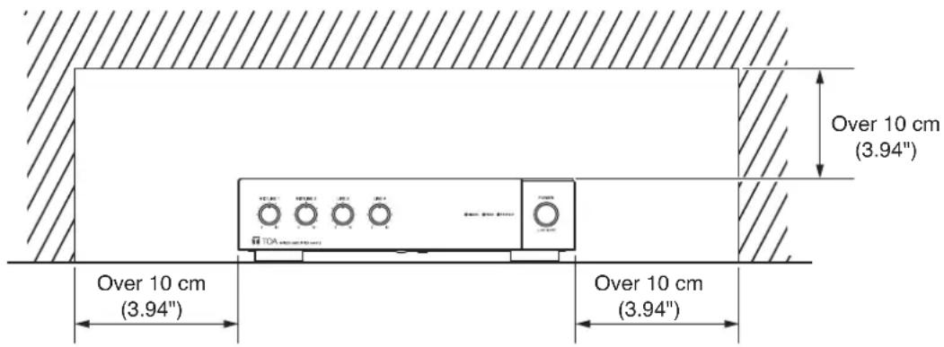
text_image
Over 10 cm (3.94") Over 10 cm (3.94") Over 10 cm (3.94")7. NOMENCLATURE AND FUNCTIONS
[Front]
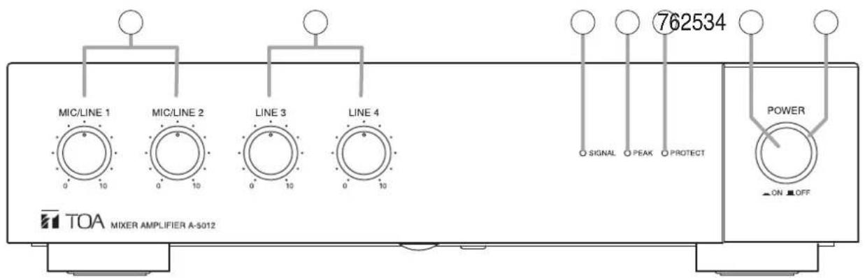
text_image
MIC/LINE 1 MIC/LINE 2 LINE 3 LINE 4 762534 SIGNAL PEAK PROTECT POWER ON OFF TOA MIXER AMPLIFIER A-S012The figure shows the A-5012.
1. Power switch
Turns unit power ON and OFF with each press of the switch.
Note
When re-using contents set with the A-5000 PC Setting software, be sure to save the contents to the preset memory before turning the power OFF. The set contents will be lost if the power is switched off before Save procedure is completed. For details, please read the software instruction manual on the supplied CD.
2. Power indicator (Green)
Lights green when power is switched ON, and extinguishes when power is switched OFF.
3. MIC/LINE input volume controls (1, 2)
Adjusts the sound volume of MIC/LINE Input 1 or 2.
4. LINE input volume controls (3, 4)
Adjusts the sound volume of LINE Input 3 or 4.
5. Signal indicator (Green)
Lights when the sound volume of any signal input exceeds the specified level (-20 dB from the rated output level).
6. Peak indicator (Red)
Lights when the sound volume of any signal input reaches a high level (-3 dB from the rated output level).
Note
Adjust the sound volume to prevent this indicator from continually lighting. If it remains lit, sound output could be distorted.
7. Failure indicator (Red)
Lights when the unit's protection circuitry is in operation (when a failure is detected) or when the fan fails.
Note
When this indicator lights, both the Signal Indicator (5) and Peak Indicator (6) will extinguish.
[Rear]
![TOA A5012 - [Rear] - 1](/content/2026/03/527580/images/458145801bc2bea815a2a2cc750ec0832e1019d42aa52fee8e30875b9c6d56bf.jpg)
text_image
100V-240V ~ 50/60Hz 39W FG SG SPEAKER OUTPUT CLASS 2 WIRING LAN USB LINE 4 LINE 3 R MOTE MASTER VOLUME + - - - - - - - - - - - - - - - - - - - - - - - - - - - - - - - - - - - - - - - - - - - - - - - - - - - - - - - - - - - - - - - - - - - - - - - - - - - - - - - - - - - - - - - - - - - - - - - - - - - - - 1. MIC/LINE 1 2. MIC/LINE 2 3. MAINT 4.100V.70V/4ΩThe figure shows the A-5012.
8. AC Power input terminal
Use the supplied power cord to connect the unit to an AC power source.
9. Functional ground terminal
Connect this terminal to the functional ground of external equipment if much noise is encountered when the unit is connected to the external equipment. The noise may be reduced.
Note: This ground is not for protective ground.
10. Line input jacks (3, 4)
RCA jack x 2
-20 dB, 10 kΩ, unbalanced
(See p. 14, "Inputs 3 and 4 connections.")
11. Manual muting terminals
Removable terminal block (5 pins).
Short circuit current: 3 mA or less
Release voltage: 24 V DC or less.
The muting function is enabled by connection of a no-voltage contact (such as a switch).
(See p. 16, "Manual muting terminal connections.")
Note
A push-button switch or similar device must first be connected to the unit and settings performed using the A-5000 PC Software.
12. MIC/LINE input terminals (1, 2)
MIC: -60 dB
LINE: -20 dB
Removable terminal block (5 pins).
2.2 kΩ, electronically balanced input.
Input sensitivity can be selected from LINE and MIC input levels.
(See p. 14, "Inputs 1 and 2 connections.")
Note
Input sensitivity is selected at the DIP switch (18).
13. Ground lifting terminal
If the unit is connected to other equipment and a resulting ground loop causes hum noise, remove the plug connected to this terminal to reduce the noise.
14. Speaker output terminals
Removable terminal block (5 pins).
(See p. 15, "Speaker Output Signal Connections.")
The following table shows each output's specifications:
| A-5006 A-5012 | |||
| Rated output 60 W 120 W | |||
| Low-impedance 4 Ω 4 Ω | |||
| High-impedance | 100 V line | 170 Ω | 83 Ω |
| 70 V line | 83 Ω | 42 Ω | |
Note
Avoid simultaneously using both the high- and low-impedance terminals. Also, do not use the high-impedance 100 V line terminal simultaneously with the 70 V line terminal, as this could result in unit failure.
Tip
Use the DIP switch (18) to switch between high-and low-impedance output.
15. LAN port
Ethernet RJ-45 port.
Use a Category 5 (or higher) straight LAN cable to connect this port to a 100BASE-TX-compatible network.
(See p. 16, "Connection to PCs.")
16. USB port
Not used.
17. Remote master volume adjustment terminals
Removable terminal block (5 pins).
Release voltage: 24 V DC or less.
The unit's master volume control can be remotely operated by connecting an external resistor to these terminals.
(See p. 16, "Remote master volume adjustment terminal connection.")
Note
Use a 10 kΩ variable resistor (B curve) for the external resistor.
If the resistor's resistance value is small, the unit's sound level will be reduced, and if the resistance value is large, the sound level will be increased.
18.DIPswitch
Used to select the input sensitivities of Inputs 1 and 2 and the output impedance of the speaker terminals.
- Switch 1
Selects Input 1 sensitivity.
UP: LINE
DOWN: MIC
- Switch 2
Selects Input 2 sensitivity.
UP: LINE
DOWN: MIC
- Switch 3
Not used. Leave this switch in its default position (UP).
- Switch 4
Switches the speaker output between low and high impedance.
UP: Low-impedance
DOWN: High-impedance
Note
All switches of the DIP switch are factory-preset to the UP position.
[Left Side]
![TOA A5012 - [Left Side] - 1](/content/2026/03/527580/images/47d9524ba198832937d9934cbdb7190416a39452eb1d38b10e7eb9620a41d140.jpg)
natural_image
Technical line drawing of a rectangular electronic device with internal components and mounting feet (no text or symbols)19.Fan
Exhaust fan.
Note
Avoid blocking the fan, as this could result in unit failure.
8. CONNECTION EXAMPLES
[Example 1]
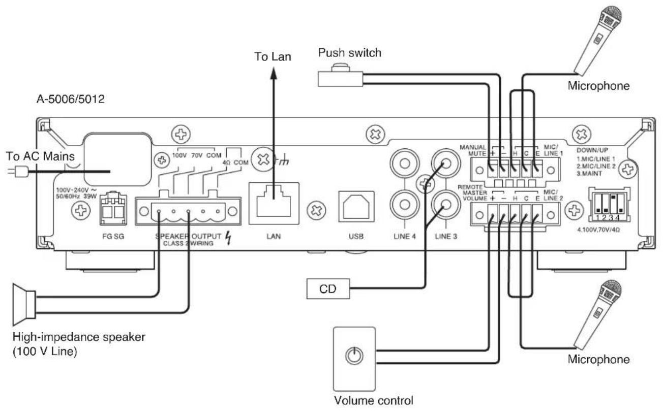
text_image
A-5006/5012 To AC Mains 100V-240V ~ 50/60Hz 39W FG SG SPEAKER OUTPUT CLASS 2 WIRING LAN USB LINE 4 LINE 3 Push switch To Lan CD High-impedance speaker (100 V Line) Microphone Microphone MANUAL MUTE H C E LINE 1 DOWN/UP 1.MIC/LINE 1 2.MIC/LINE 2 3.MAINT REMOTE MASTER VOLUME + - H C E LINE 2 4.100V,70V/4Ω Volume control[Example 2]
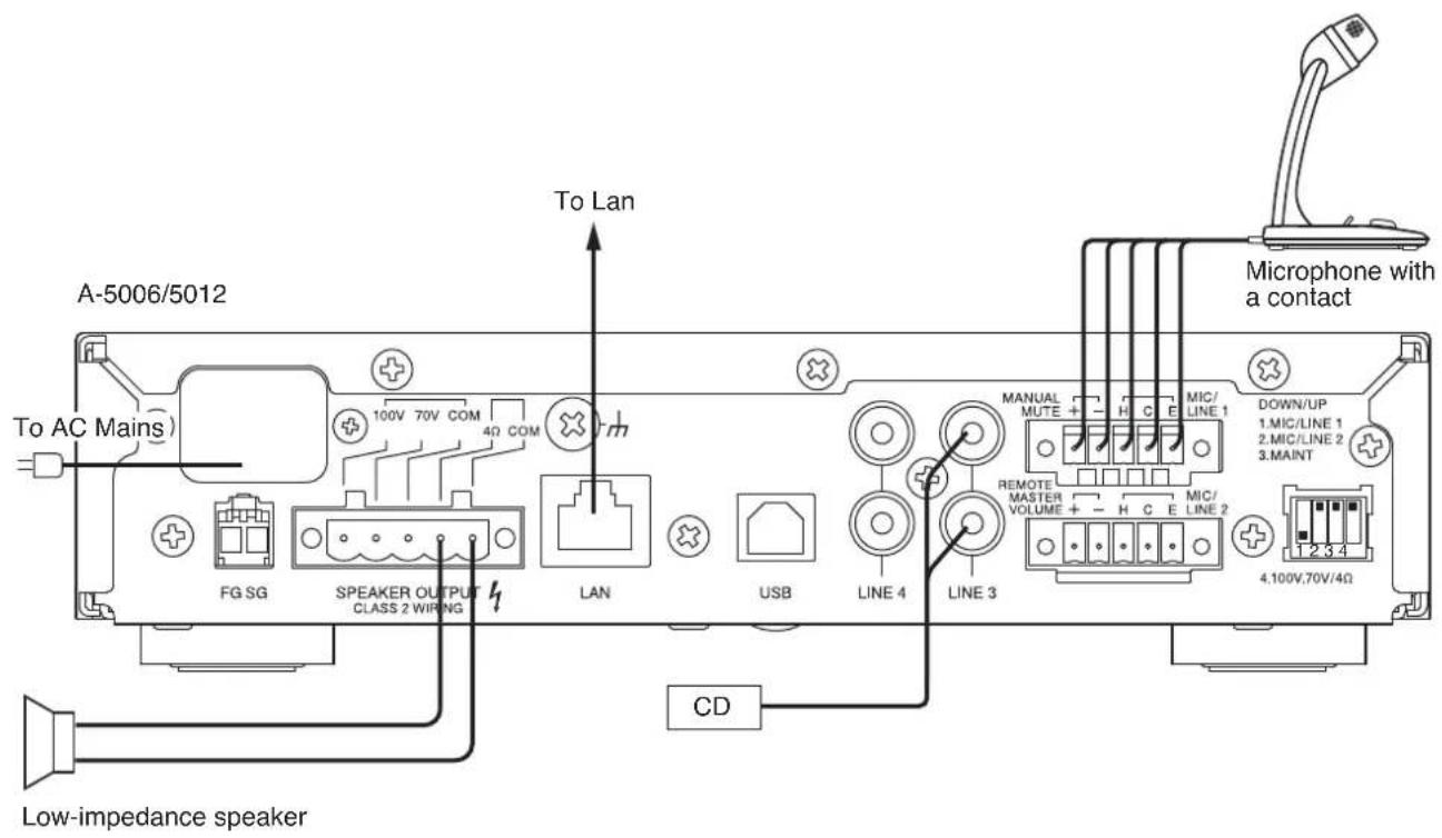
text_image
A-5006/5012 To AC Mains) FG SG SPEAKER OUTPUT CLASS 2 WIRING LAN USB LINE 4 LINE 3 CD Low-impedance speaker To Lan Microphone with a contact MANUAL MUTE + H C E MIC/ LINE 1 DOWN/UP 1.MIC/LINE 1 2.MIC/LINE 2 3.MAINT 4.100V,70V/4Ω9. CONNECTION
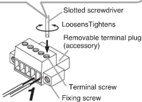
9.1. Removable Terminal Plug Connection
Step 1. Wiring the supplied removable terminal plug.
1-1. Loosen the terminal screws to insert the wire.
1-2. Tighten the terminal screws.
Ensure that the wire does not break free when pulled. If the wire does pull free, repeat the connection procedure from the start.
Step 2. Insert the wired terminal plug into the corresponding terminal block in the unit's rear panel.
Step 3. Tighten the fixing screw.
Notes
- Do not reverse Steps 1 and 2 above. Poor contact may result if force is applied to the unit's internal circuit board pins while the terminal screws are being tightened.
- When detaching the terminal plug, pull it straight out. Pulling it out at an angle may cause the terminal plug or terminal block to break.
[Recommended type of screwdriver]

text_image
Blade width*1*1 For speaker output terminal: About 3.5 mm (0.14") For other terminals: About 2.5 mm (0.1")
text_image
Slotted screwdriver LoosensTightens Removable terminal plug (accessory) Terminal screw Fixing screwTips
• Applicable cable size
| For speaker output terminal For other terminals | ||
| Conductor cross-section area | 0.2 – 2.5 mm^2 | 0.14 – 1.5 mm^2 |
| AWG | AWG 24 – 12 or equivalent | AWG 28 – 16 or equivalent |
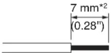
- Cable sheath to trim
Solid cable and stranded cable
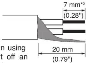
Shielded cable
text_image
7 mm*2 (0.28") n using t off an 20 mm (0.79")Note
Avoid soldering stranded or shielded cable, as contact resistance may increase when the cable is tightened and the solder is crushed, possibly resulting in an excessive rise in joint temperatures.
*2 Expose 8 mm (0.31") or more when using the above ferrule terminal, and cut off an extra conductor protruding from the sleeve.
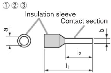
- When connecting 2 cables or a shielded cable to a single terminal, use a ferrule terminal with an insulation sleeve to crimp the cables because such cable conductors could become loose.
(1) Recommended ferrule terminals for signal cables
(made by Phoenix Contact) Unit: mm (in)
| Model Number | a | b | l_1 | l_2 | |
| 1 | AI 0,34-8 TQ | 2 (0.08) | 0.8 (0.03) | 12.5 (0.49) | 8 (0.31) |
| 2 | AI 0,5-8 WH | 2.5 (0.1) | 1.1 (0.04) | 14 (0.55) | 8 (0.31) |
(2) Recommended ferrule terminals for speaker cables
(made by Phoenix Contact)
Unit: mm (in)
| Model Number | a | a_1 | a_2 | b | l_1 | l_2 | |
| 3 | AI 1,5-8 BK | 3.4 (0.31) | — | — | 1.8 (0.07) | 14 (0.55) | 8 (0.31) |
| 4 | AI-TWIN 2 x 1,5-8 BK | — | 6.6 (0.26) | 3.6 (0.14) | 2.3 (0.09) | 16 (0.63) | 8 (0.31) |
Crimping tool: CRIMPFOX 10S (made by Phoenix Contact)
text_image
①②③ Insulation sleeve Contact section a b l₂ l₁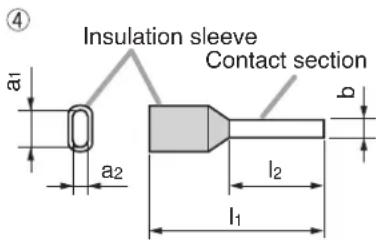
text_image
Insulation sleeve Contact section a1 a2 b l2 l19.2. How to Connect Input Signals
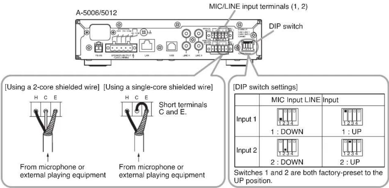
9.2.1. Inputs 1 and 2 connections
Use the supplied Small type removable terminal plug (5 pins) for connection. Inputs 1 and 2 can be set to MIC or LINE input.
When setting, use Switch 1 of the DIP switch for the Input 1 connection and Switch 2 for the Input 2 connection.
text_image
A-5006/5012 MIC/LINE input terminals (1, 2) DIP switch [Using a 2-core shielded wire] [Using a single-core shielded wire] H C E From microphone or external playing equipment H C E Short terminals C and E. From microphone or external playing equipment [DIP switch settings] Input 1 1 : DOWN 1 : UP Input 2 2 : DOWN 2 : UP Switches 1 and 2 are both factory-preset to the UP position.9.2.2. Inputs 3 and 4 connections
Inputs 3 and 4 are intended exclusively for LINE input.
When connecting a monaural sound source, connect the L line.
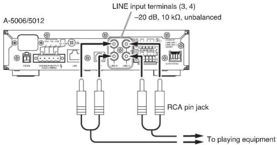
text_image
A-5006/5012 LINE input terminals (3, 4) -20 dB, 10 kΩ, unbalanced FIS SD SPEAKER OUTPUT CLASS CIRCUA LAN LINE 4 LINE 3 RCA pin jack To playing equipmentNote: L and R line signals are mixed inside the unit.
9.3. Speaker Output Signal Connections
The unit can be connected to high- or low-impedance speakers. Class 2 wiring may be used.
Using the supplied Large type removable terminal plug (5 pins), connect the speaker line to any pair of terminals from among the following three combinations.
Also, perform the impedance setting using Switch 4 of the DIP switch.
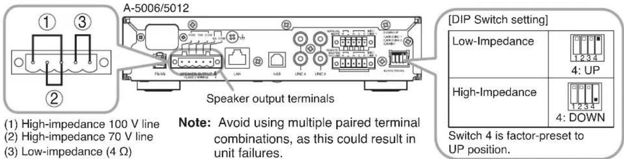
(1) High-impedance 100 V line
(2) High-impedance 70 V line
(3) Low-impedance (4 Ω)
Note: Avoid using multiple paired terminal combinations, as this could result in unit failures.
[DIP Switch setting]
| Low-Impedance | |
| High-Impedance | |
Switch 4 is factor-preset to UP position.
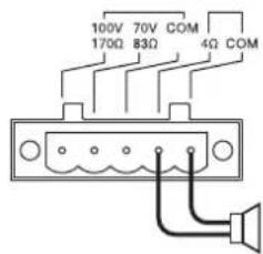
9.3.1. High-impedance 100 V line speaker connections
[For A-5012] [For A-5006]
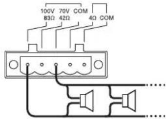
text_image
100V 70V COM 83Ω 42Ω 4Ω COMTotal wattage: 120 W or less
Total impedance: 83 Ω or more
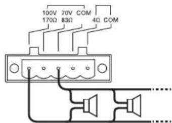
text_image
100V 70V COM 170Ω 83Ω 4Ω COMTotal wattage: 60 W or less
Total impedance: 170 Ω or more
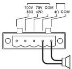
9.3.2. High-impedance 70 V line speaker connections
[For A-5012] [For A-5006]
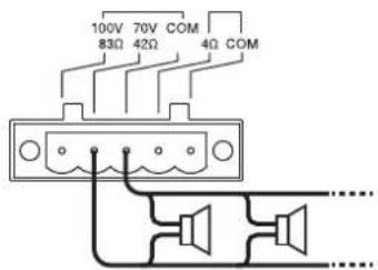
text_image
100V 70V COM 83Ω 42Ω 4Ω COMTotal wattage: 120 W or less
Total impedance: 42 Ω or more
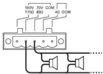
text_image
100V 70V COM 170Ω 83Ω 4Ω COMTotal wattage: 60 W or less
Total impedance: 83 Ω or more
9.3.3. Low-impedance speaker connections
[For A-5012] [For A-5006]
text_image
100V 70V COM 83Ω 42Ω 4Ω COMImpedance: 4 to 16 Ω
Rated input of speaker: 120 W or more
text_image
100V 70V COM 170Ω 83Ω 4Ω COMImpedance: 4 to 16 Ω
Rated input of speaker: 60 W or more
9.4. Remote Control Equipment Connections
Use the supplied Small type removable terminal plug (5 pins) for connection.
9.4.1. Manual muting terminal connections
If a no-voltage contact is connected, closing the contact allows the pre-determined input channel volume to be reduced by a preset level of attenuation.
If a microphone with a contact is connected as shown in Connection Example 2 (p. 12), the audio of other channels will be muted for as long as the microphone's talk switch is pressed.
Use the A-5000 PC Software to enable or disable this function, select the input channel, and set the attenuation. For details, please read the software instruction manual on the supplied CD.
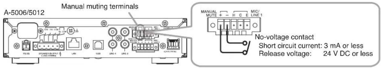
text_image
A-5006/5012 Manual muting terminals MANUAL MUTE + - H C E MIC/ LINE 1 No-voltage contact Short circuit current: 3 mA or less Release voltage: 24 V DC or less9.4.2. Remote master volume adjustment terminal connection
The unit's master volume can be remotely adjusted by an externally-connected resistor.
If the resistor's resistance value is small, the unit's sound level will be reduced, and if the resistance value is large, the sound level will be increased.
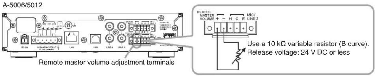
text_image
A-5006/5012 Remote master volume adjustment terminals Use a 10 kΩ variable resistor (B curve). Release voltage: 24 V DC or less9.5. Connection to PCs
Connect a PC via a switching hub.
For details, please read the software instruction manual on the supplied CD.
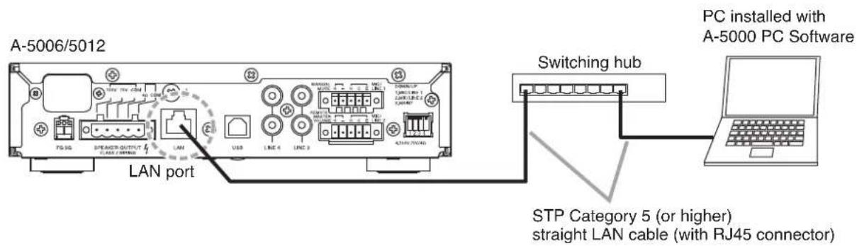
text_image
A-5006/5012 LAN port STP Category 5 (or higher) straight LAN cable (with RJ45 connector) Switching hub PC installed with A-5000 PC Software10. RACK-MOUNTING THE MIXER AMPLIFIER
To mount the unit in an equipment rack, use the optional YA-706 guide rail and either the MB-15B-BK (for 1 unit) or MB-15B-J (for 2 units) bracket set. Before mounting, remove the four plastic feet attached to the bottom surface of the unit.
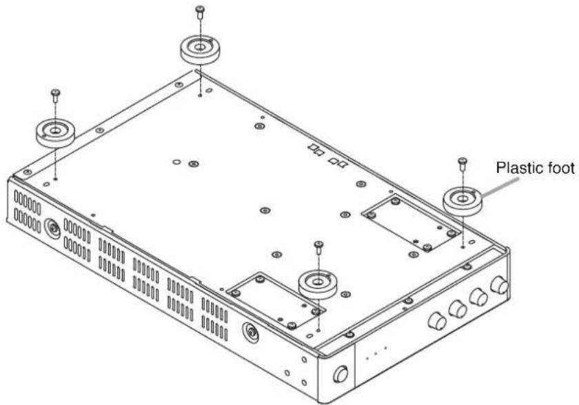
text_image
Plastic footNote
To improve ventilation, ensure that a perforated panel (panel with air openings) of 1-unit size or greater is mounted over and under each unit, as well as on the top and at the bottom of the rack.
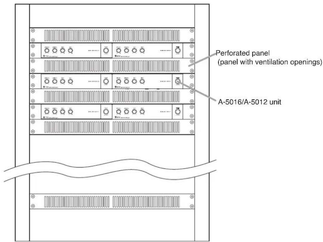
text_image
Perforated panel (panel with ventilation openings) A-5016/A-5012 unitStep 1. Fix the optional guide rail YA-706 loosely to the rack frame.
Note
The figures below show the way to install the YA-706 to the left side of the rack. Follow the same procedure for installation to the right side.
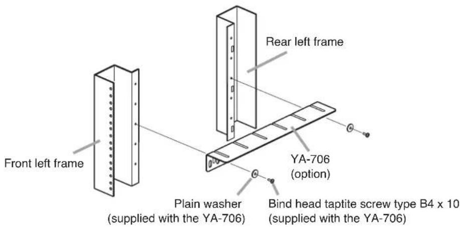
text_image
Front left frame Rear left frame Plain washer (supplied with the YA-706) YA-706 (option) Bind head taptite screw type B4 x 10 (supplied with the YA-706)Note
To install the YA-706, use its second front hole and rearmost hole as shown at right.
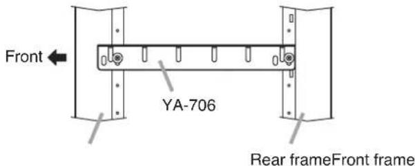
text_image
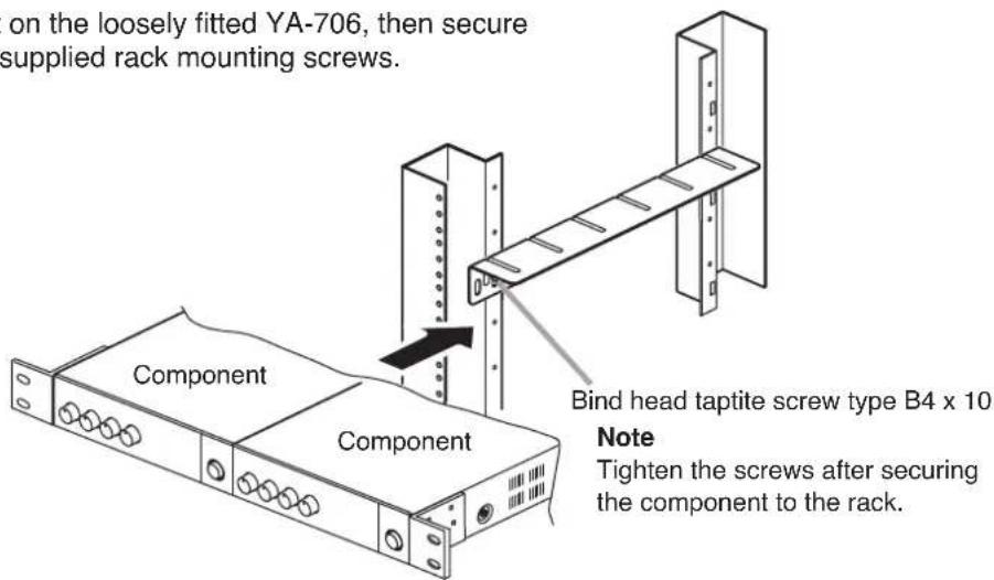
Front YA-706 Rear frameFront frameStep 2. Place the component on the loosely fitted YA-706, then secure it to the rack with the supplied rack mounting screws.
text_image
on the loosely fitted YA-706, then secure supplied rack mounting screws. Component Component Bind head taptite screw type B4 x 10 Note Tighten the screws after securing the component to the rack.2-1. When mounting a single unit
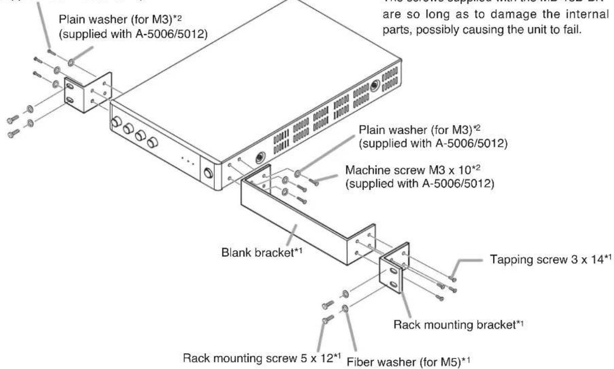
Use the optional MB-15B-BK hardware set.
*1 Component parts of MB-15B-BK
\*2 Note
Never use the screws supplied with the MB-15B-BK to mount the bracket. The screws supplied with the MB-15B-BK are so long as to damage the internal parts, possibly causing the unit to fail.
Machine screw M3 x 10*2 (supplied with A-5006/5012)
text_image
Plain washer (for M3)*2 (supplied with A-5006/5012) are so long as to damage the internal parts, possibly causing the unit to fail. Plain washer (for M3)*2 (supplied with A-5006/5012) Machine screw M3 x 10*2 (supplied with A-5006/5012) Blank bracket* Tapping screw 3 x 14*1 Rack mounting bracket* Rack mounting screw 5 x 12*1 Fiber washer (for M5)*12-2. When mounting 2 units
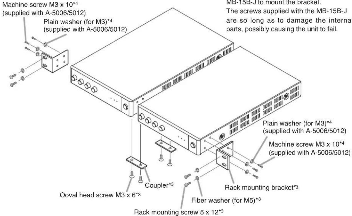
Use the optional MB-15B-J hardware set
*3 Component parts of MB-15B-J
\*4 Note
Never use the screws supplied with the MB-15B-J to mount the bracket.
The screws supplied with the MB-15B-J are so long as to damage the internal parts, possibly causing the unit to fail.
text_image
Machine screw M3 x 10*4 (supplied with A-5006/5012) Plain washer (for M3)*4 (supplied with A-5006/5012) Oval head screw M3 x 6*3 Coupler*3 Rack mounting screw 5 x 12*3 Fiber washer (for M5)*3 Plain washer (for M3)*4 (supplied with A-5006/5012) Rack mounting bracket*3 MB-15B-J to mount the bracket. The screws supplied with the MB-15B-J are so long as to damage the internal parts, possibly causing the unit to fail.Step 3. Lift up the YA-706 until they hold the component, then secure them.
11. BLOCK DIAGRAM
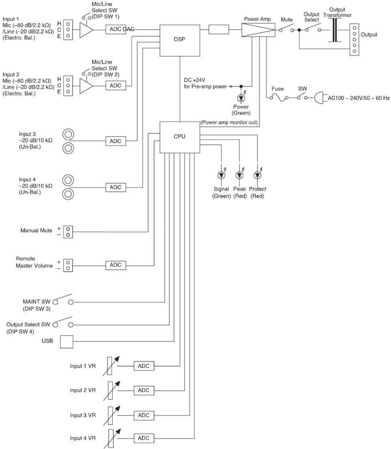
flowchart
graph TD
    A["Input 1 Mic (-60 dB/2.2 kΩ) /Line (-20 dB/2.2 kΩ) (Electro. Bal.)"] --> B["HC E"]
    B --> C["ADC DAC"]
    C --> D["DSP"]
    D --> E["Power Amp"]
    E --> F["Mute"]
    F --> G["Output Transformer"]
    G --> H["Output"]

    I["Input 2 Mic (-60 dB/2.2 kΩ) /Line (-20 dB/2.2 kΩ) (Electro. Bal.)"] --> J["HC E"]
    J --> K["ADC"]
    K --> L["CPU"]
    L --> M["DC +24V for Pre-amp power"]
    M --> N["Power (Green)"]
    N --> O["Fuse SW AC100 - 240V/50 - 60 Hz"]

    P["Input 3 -20 dB/10 kΩ (Un-Bal.)"] --> Q["○"]
    R["Input 4 -20 dB/10 kΩ (Un-Bal.)"] --> S["○"]
    T["Manual Mute"] --> U["+"]
    V["Remote Master Volume"] --> W["+"]
    X["MAINT SW (DIP SW 3)"] --> Y["○"]
    Z["Output Select SW (DIP SW 4)"] --> AA["○"]
    AB["USB"] --> AC["ADC"]

    AD["Input 1 VR"] --> AE["ADC"]

    AF["Input 2 VR"] --> AG["ADC"]

    AH["Input 3 VR"] --> AI["ADC"]

    AJ["Input 4 VR"] --> AK["ADC"]
12. DIMENSIONAL DIAGRAM
[FRONT]
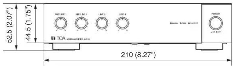
text_image
52.5 (2.07") 44.5 (1.75") TOA MICROAMPLIFIER 210 (8.27)Unit : mm
The figure shows the A-5012. The dimensions of A-5006 are same as A-5012.
[SIDE]
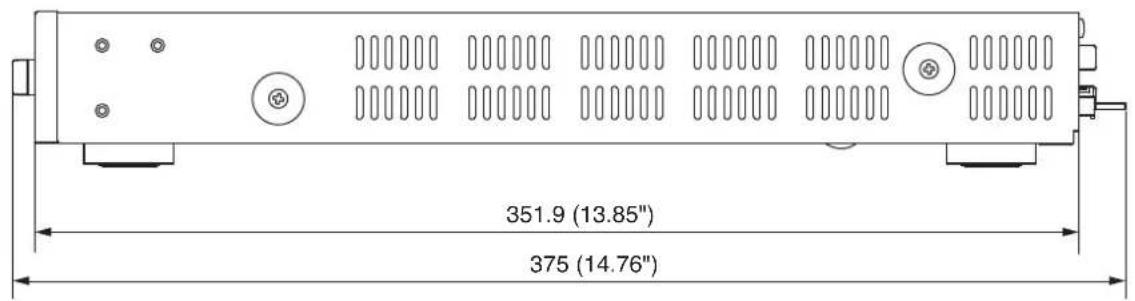
text_image
351.9 (13.85") 375 (14.76)13. SPECIFICATIONS
| Model No. A-5006 | A-5012 | ||
| Power Source 100 – 240 | V AC, 50/60 Hz | ||
| Rated Output 60 W 120 W | |||
| Power Consumption 105 W (rated output),20 W (based on cULus standards) | 207 W (rated output),39 W (based on cULus standards) | ||
| Current Consumption Max. 2 A Max. 3 A | |||
| Frequency Response 50 Hz – 20 kHz (1/8 rated output) | |||
| Distortion | 1% or less (1 kHz, rated output) | ||
| Input | INPUT 1, 2 | MIC: -60 dB*/LINE: -20 dB* (MIC/LINE selectable)2.2 kΩ, electronically-balanced, removable terminal block (5 pins) | |
| INPUT 3, 4 | LINE: -20 dB*, 10 kΩ, unbalanced, RCA pin jack | ||
| Output | SPEAKER | 4 Ω, 70 V (83 Ω), 100 V (170 Ω),removable terminal block (5 pins) | 4 Ω, 70 V (42 Ω), 100 V (83 Ω),removable terminal block (5 pins) |
| Signal to Noise Ratio | MIC 1, 2: 50 dB or more, LINE 1 – 4: 70 dB or more (A-weighted) | ||
| Function | Equalizer: 5 points settable on each input (High-pass filter x 1, Parametric equalizer x 4)HPF: 20 Hz – 20 kHz (6 dB/oct)PEQ: 20 Hz – 20 kHz ± 15 dB, Q: 0.267 – 69.249FBS: ON/OFF settable on inputs 1 and 2 (OFF by default)Compressor: ON/OFF settable on inputs 1 and 2 (OFF by default)Threshold, Ratio, Attack time, Release time, and Gain are settableindependently on each input.Mute: MANUAL/AUTO/OFF settable on each input (MANUAL by default)Reduction level, Hold time and Fade-in time are settable independently oneach input.Trigger threshold is settable independently on input 1. (AUTO)Equalizer: 10 points settable on output. (Through, Low-pass filter, Parametric equalizer,High-pass filter)LPF: 20 Hz – 20 kHz (6 dB/oct)LPF: 20 Hz – 20 kHz (12 dB/oct)PEQ: 20 Hz – 20 kHz ± 15 dB, Q: 0.267 – 69.249HPF: 20 Hz – 20 kHz (6 dB/oct)HPF: 20 Hz – 20 kHz (12 dB/oct)Speaker Parametric equalizer: 5 points settable on output20 Hz – 20 kHz ± 15 dBQ: 0.267 – 69.249 | ||
| Control | Mute control, Remote master volume control, Power ON/OFF switch, Ground lift | ||
| LED Indicator | Power indicator, Signal indicator, Peak indicator, Protect indicator | ||
| Network I/F | 100BASE-TX | ||
| Operating Temperature | 0 to 40 °C (32 to 104 °F) | ||
| Operating Humidity | 35 to 80 %RH (no condensation) | ||
| Finish | Panel: PS resin, blackCase: Surface-treated steel plate, black, paint | ||
| Dimensions | 210 (w) x 52.5 (h) x 375 (d) mm (8.27" x 2.07" x 14.76") | ||
| Weight 3.6 kg (7.94 lb) | 3.9 kg (8.6 lb) | ||
* 0 dB = 1 V
Note: The design and specifications are subject to change without notice for improvement.
- Accessories
CD (setting software) 1
Large type removable terminal plug (5 pins) ..... 1
Small type removable terminal plug (5 pins) ..... 2
Machine screw M3 x 10....6
Plain washer (for M3) 6
Power supply cord (2 m or 6.56 ft) 1
- Optional products
Half width blank panel: MB-15B-BK (for rack mounting 1 unit)
Rack joint bracket: MB-15B-J (for rack mounting 2 units)
Rack runner: YA-706
FCC REQUIREMENTS
Note
This equipment has been tested and found to comply with the limits for a Class A digital device, pursuant to Part 15 of the FCC Rules. These limits are designed to provide reasonable protection against harmful interference when the equipment is operated in a commercial environment. This equipment generates, uses, and can radiate radio frequency energy and, if not installed and used in accordance with the instruction manual, may cause harmful interference to radio communications.
Operation of this equipment in a residential area is likely to cause harmful interference in which case the user will be required to correct the interference at his own expense.
Modifications
Any modifications made to this device that are not approved by TOA Corporation may void the authority granted to the user by the FCC to operate this equipment.
This Class A digital apparatus complies with Canadian ICES-003.
Any modification to the unit, unless expressly approved by TOA Electronics, Inc., could void your authority to operate the equipment.
DECLARATION OF CONFORMITY
TOA Electronics, Inc.
400 Oyster Point Boulevard, Suite 301, South San Francisco,
California 94080, USA
TEL 650-452-1200
declare under our sole responsibility that the product
MIXER AMPLIFIER
A-5006 3CU, A-5012 3CU
comply with Part 15 of FCC Rules.
Operation is subject to the following conditions: (1) this device may not cause harmful interference, and (2) this device must accept any interference received, including interference that may cause undesired operation.
Traceability Information for Europe
Manufacturer:
TOA Corporation
7-2-1, Minatojima-Nakamachi, Chuo-ku, Kobe, Hyogo, Japan
Authorized representative:
TOA Electronics Europe GmbH
Suederstrasse 282, 20537 Hamburg, Germany
URL: http://www.toa.jp/
133-02-00212-02