
P250061 - Fan Progress Lighting - Free user manual and instructions
Find the device manual for free P250061 Progress Lighting in PDF.

User questions about P250061 Progress Lighting
0 question about this device. Answer the ones you know or ask your own.
Ask a new question about this device
Download the instructions for your Fan in PDF format for free! Find your manual P250061 - Progress Lighting and take your electronic device back in hand. On this page are published all the documents necessary for the use of your device. P250061 by Progress Lighting.
USER MANUAL P250061 Progress Lighting
natural_image
Line drawing of a five-blade cabinet fan with three blades and a top-mounted head (no text or symbols)93133624_A
P250061
Limited Lifetime Warranty
Progress Lighting fan motors are warranted to the original purchaser to be free of electrical and/or mechanical defects for so long as the original purchaser owns the fan. Pull chain switches, reverse switches, capacitors and metal finishes are warranted to be free from defects in materials or workmanship for a period of 1 year from the date of purchase. Warping of wooden or plastic blades is not covered by this warranty nor is corrosion and/or deterioration of any finishes for fans installed within ten miles of any sea coast. Extended warranties for ENERGY STAR ^® qualified products may apply.
Progress Lighting ceiling fans with built-in LED light sources, when properly installed and under normal conditions of use, are warranted to be free from defects in material and workmanship which cause the light sources to fail to operate in accordance with the specifications for (i) five (5) years from the date of purchase on the LED Light modules and electrical components for fans used in single family residences, and (ii) three (3) years from the date of purchase on the LED Light modules and electrical components for fans used in multi-family or commercial applications. LED bulbs supplied by Progress Lighting carry no warranty other than manufacturer's warranty. Non-LED bulbs carry no warranty.
With proof of purchase, the original purchaser may return the defective fan to the place of purchase during the first 30 days for replacement. After 30 days, the original purchaser MUST contact Progress Lighting at (864) 678-1000 for repair or replacement which shall be determined in Progress Lighting's sole discretion and shall be purchaser's sole and exclusive remedy.
Labor and Shipping Excluded. This warranty does not cover any costs or fees associated with the labor (including, but not limited to, electrician's fees) required to install, remove, or replace a fan or any fan parts.
This warranty shall not apply to any loss or damage resulting from (i) normal wear and tear or alteration, misuse, abuse or neglect, or (ii) improper installation, operation, repair or maintenance by original purchaser or a third party, including without limitation improper voltage supply or power surge, use of improper parts or accessories, unauthorized repair (made or attempted) or failure to provide maintenance to the fan.
THE FOREGOING WARRANTIES STATE PROGRESS LIGHTING'S ENTIRE WARRANTY OBLIGATION AND ORIGINAL PURCHASER'S SOLE AND EXCLUSIVE REMEDY RELATED TO SUCH PRODUCTS. PROGRESS LIGHTING IS NOT RESPONSIBLE FOR DAMAGES (INCLUDING INDIRECT, SPECIAL, INCIDENTAL OR CONSEQUENTIAL), DUE TO PRODUCT FAILURE, WHETHER ARISING OUT OF BREACH OF WARRANTY, BREACH OF CONTRACT, OR OTHERWISE. THIS WARRANTY IS GIVEN IN LIEU OF ALL OTHER WARRANTIES, WHETHER EXPRESSED OR IMPLIED, INCLUDING THOSE OF MERCHANTABILITY, FITNESS FOR A PARTICULAR PURPOSE OR NONINFRINGEMENT.
Some states do not allow limitations on how long an implied warranty lasts or the exclusion or limitations of incidental or consequential damages, so the above limitations and exclusions may not apply to you. This warranty gives you specific rights and you may have other rights which vary from state to state.
Date Purchased ____
Store Purchased ____
UL Model No. P250061
Serial No. ____
Vendor No. 111017
UPC 785247264926
785247264933
PROGRESS LIGHTING™
Safety Rules.... 1
Unpacking Your Fan 2
Installing Your Fan....3
Making the Electrical Connections....6
Remote Control....10
Operating Your Fan ....11
Care of Your Fan. 12
Troubleshooting 12
Specifications ......13
Table of Contents
READ AND SAVE THESE INSTRUCTIONS
-
To reduce the risk of electric shock, insure electricity has been turned off at the circuit breaker or fuse box before beginning.
-
All wiring must be in accordance with the National Electrical Code ANSI/NFPA 70-1999 and local electrical codes. Electrical installation should be performed by a qualified licensed electrician.
-
CAUTION: To reduce the risk of personal injury, use only the screws provided with the electrical box.
-
The outlet box and support structure must be securely mounted and capable of reliably supporting 35 lbs. (15.9 kg). Use only cUL Listed outlet boxes marked “Acceptable for Fan Support of 35 lbs. (15.9 kg) or less.”
-
CAUTION: The fan must be mounted with a minimum of 7 feet clearance from the trailing edge of the blades to the floor.
-
Do not wait for the fan to stop before pressing the reverse button. The fan will not reverse direction if the fan is not moving.
-
Avoid placing objects in path of the blades.
WARNING
TO REDUCE THE RISK OF FIRE, ELECTRIC SHOCK OR PERSONAL INJURY, MOUNT TO OUTLET BOX MARKED "ACCEPTABLE FOR FAN SUPPORT OF 35LBS. (15.9 KG) OR LESS", AND USE SCREWS PROVIDED WITH THE OUTLET BOX.
WARNING
TO REDUCE THE RISK OF PERSONAL INJURY, DO NOT BEND THE BLADE BRACKETS (ALSO REFERRED TO AS ("FLANGES")) DURING ASSEMBLY OR AFTER INSTALLATION. DO NOT INSERT OBJECTS IN THE PATH OF THE BLADES.
1. Safety Rules
-
To avoid personal injury or damage to the fan and other items, be cautious when working around or cleaning the fan.
-
Do not use water or detergents when cleaning the fan or fan blades. A dry dust cloth or lightly dampened cloth will be suitable for most cleaning.
-
After making electrical connections, spliced conductors should be turned upward and pushed carefully up into electrical box. The wires should be spread apart with the grounded conductor and the equipment-grounding conductor on one side of the electrical box and ungrounded conductor on the other side of the electrical box.
-
Electrical diagrams are for reference only. Light kits that are not packed with the fan must be cUL Listed and marked suitable for use with the model fan you are installing. Switches must be cUL General Use Switches. Refer to the instructions packaged with the light kits and switches for proper assembly.
-
All set screws must be checked and retightened where necessary before installation.
-
WARNING: To reduce the risk of fire or electric shock, this fan should only be used with fan speed control part no. DP-52R, manufactured by DAWNSUN ELECTRONIC TECHNOLOGY CO LTD ZHONGSHAN.
WARNING
TO REDUCE THE RISK OF SHOCK, THIS FAN MUST BE INSTALLED WITH AN ISOLATION WALL CONTROL/SWITCH.
text_image
1 2 3 4 5 6 7 8 9 10 11 12
natural_image
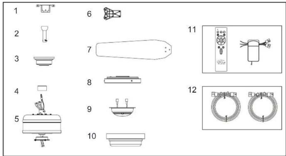
Three technical diagrams labeled a, b, and c showing different mechanical or electrical component layouts (no text or symbols present)Unpack your fan and check the contents. You should have the following items:
- Mounting Bracket
- 6" Ball/Downrod Assembly (hanger pin and locking pin pre-attached)
- Canopy with Canopy Ring (attached)
- Decorative Motor Collar Cover
-
Fan Motor Assembly
-
Blade brackets (5)
- Blades (5)
- Light Kit Pan
- Light Kit Fitter Assembly
- Light Shade
- Transmitter and Receiver
- Extension Lead Wire
a. Blade attachment hardware
(16 screws for attaching blades to blade arms)
b. Electrical hardware and balancing kit
(1 plastic wire connectors, blade balancing kit)
c. Blade bracket attachment hardware
(1 extra screw for attaching blade arms to the fan motor assembly)
2. Unpacking Your Fan
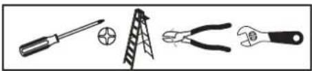
Tools Required
Phillips screw driver or straight slotted screw driver, adjustable wrench, step ladder, and wire cutters.
natural_image
Illustration of four different tools: screwdriver, ladder, pliers, and wrench (no text or symbols present)Mounting Options
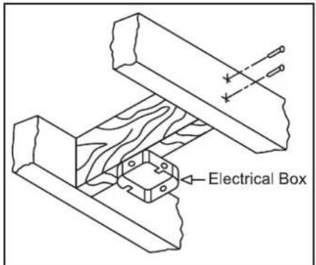
If there isn't an existing electrical box, then read the following instructions. Disconnect the power by removing fuses or turning off circuit breakers.
Secure the electrical box directly to the building structure. Use appropriate fasteners and building materials. The electrical box and its support must be able to fully support the moving weight of the fan (at least 35 lbs.). Do not use plastic electrical boxes.
WARNING
TO REDUCE THE RISK OF FIRE, ELECTRIC SHOCK OR PERSONAL INJURY, MOUNT TO OUTLET BOX MARKED "ACCEPTABLE FOR FAN SUPPORT OF 35 LBS. (15.9 KG) OR LESS", AND USE SCREWS PROVIDED WITH THE OUTLET BOX. ELECTRICAL BOXES COMMONLY USED FOR THE SUPPORT OF LIGHTING FIXTURES MAY NOT BE ACCEPTABLE FOR FAN SUPPORT AND MAY NEED TO BE REPLACED. CONSULT A QUALIFIED ELECTRICIAN IF IN DOUBT.
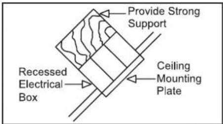
Figures 1, 2, and 3 are examples of different ways to mount the electrical box.
text_image
Electrical BoxFigure 1
text_image
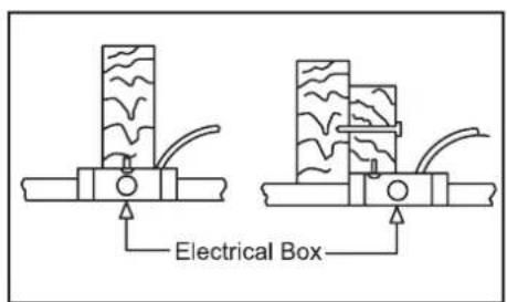
Electrical BoxFigure 2
text_image
Provide Strong Support Recessed Electrical Box Ceiling Mounting PlateFigure 3
Note: You may need a longer downrod to maintain proper blade clearance when installing on a steep, sloped ceiling. The maximum angle allowable is 20^ . If the canopy touches downrod, remove the decorative canopy bottom cover and turn the canopy 180^ before attaching the canopy to the mounting plate.
text_image
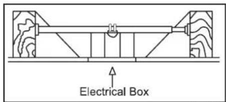
Electrical BoxFigure 4
To hang your fan where there is an existing fixture but no ceiling joist, you may need an installation hanger bar as shown in Figure 4.
3. Installing Your Fan
3. Installing Your Fan
Hanging the Fan
REMEMBER to turn off the power. Follow the steps below to hang your fan properly.
NOTE: This fan is recommended for standard ceiling mount using the downrod provided with this fan. When using standard ceiling installation with the 6 inch downrod provided, the distance from the ceiling to the bottom of the fan blades will be approximately 13.7 inches.
Standard Ceiling Mounting
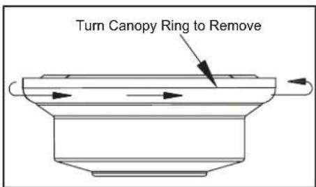
- Remove the canopy ring from the canopy by turning the ring to the right until it unlocks. (Figure 5)
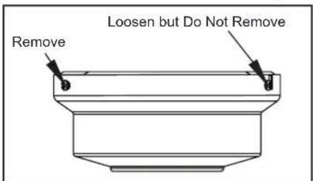
- Remove the mounting bracket from the canopy by loosening the four screws on the top of the canopy. Remove the two non-slotted screws and loosen the slotted screws. This will enable you to remove the mounting bracket. (Figure 6)
- Remove the hanger pin and locking pin from downrod assembly.
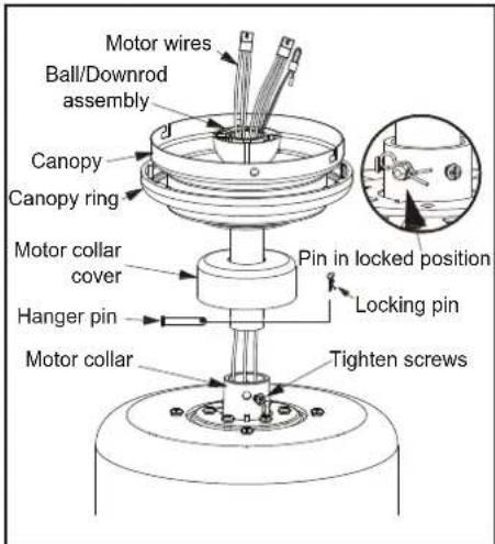
- Place downrod over canopy and canopy ring, slide the motor collar cover onto the downrod. Route the wires through the ball/downrod assembly. (Figure 7)
- Loosen, but do not remove, the set screws on the collar on the top of the motor housing.
text_image
Turn Canopy Ring to RemoveFigure 5
text_image
Loosen but Do Not Remove RemoveFigure 6
- Align the holes at the bottom of the downrod with the holes in the collar on top of the motor housing. (Figure 7)
Carefully insert the hanger pin through the holes in the collar and downrod. Be careful not to jam the hanger pin against the wiring inside the downrod. Insert the locking pin through the hole near the end of the bolt until it snaps into its locked position, as noted in the circle inset of Figure 7. -
Re-tighten the set screws on the collar on top of the motor housing.
-
Make sure the grommet is properly installed in the collar cover, then slide the collar cover on the downrod until it rests on the motor housing. Be sure that the canopy and the collar cover are both oriented correctly.
- Proceed to "Installing the Fan" section.
WARNING
FAILURE TO PROPERLY INSTALL SET SCREWS AS NOTED IN STEP 7 COULD RESULT IN FAN LOOSENING AND POSSIBLY FALLING.
text_image
Motor wires Ball/Downrod assembly Canopy Canopy ring Motor collar cover Hanger pin Motor collar Tighten screws Pin in locked position Locking pinFigure 7
Installing Fan to the Electrical Box
WARNING
WHEN USING THE STANDARD BALL/DOWNROD MOUNTING, THE TAB IN THE RING AT THE BOTTOM OF THE MOUNTING BRACKET MUST REST IN THE GROOVE OF THE HANGER BALL. FAILURE TO PROPERLY SEAT THE TAB IN THE GROOVE COULD CAUSE DAMAGE TO WIRING.
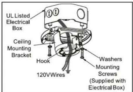
- Pass the 120-volt supply wires through the center hole in the ceiling mounting bracket as shown in Figure 8.
- Install the ceiling mounting bracket on the electrical box by using the mounting screws provided with the electrical box. Note that the flat side of the mounting bracket is toward the electrical box. (Figure 8)
- Tighten the two screws on the electrical box securely.
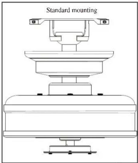
- Carefully lift the fan assembly up to the ceiling mounting bracket. Make sure the tab on the mounting bracket is properly seated in the groove in the hanger ball. (Figure 9)
text_image
UL Listed Electrical Box Ceiling Mounting Bracket Hook 120VWires Washers Mounting Screws (Supplied with Electrical Box)Figure 8
text_image
Standard mountingFigure 9
Connecting the Safety Cable
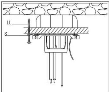
- Turn the wood screw (LL)(not provided) into the ceiling.
- Place the looped end of the safety cable (S) onto the wood screw and then tighten the screw firmly, or connect the safety cable directly to the electrical box. (Figure 10)
text_image
LL SFigure 10
Installing the Receiver into the Mounting Bracket
- Position the house supply wires to one side of the slide-on mounting bracket; position the fan wires to the opposite side.
- Insert the narrow end of the receiver (as shown, flat side toward ceiling) into the slide-on mounting bracket until it rests on top of the ball/downrod assembly. (Figure 11)
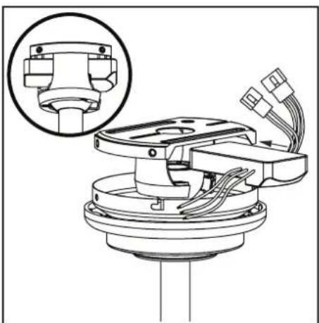
natural_image
Technical diagram of a mechanical assembly with wiring and components, no visible text or symbolsFigure 11
Wiring the Receiver to the Household Wiring
- Connect the green wire to the household ground wires using a wire connecting nut.
- Connect the receiver black wire to the household black wire using a wire connecting nut.
- Connect the receiver white wire to the household white wire using a wire connecting nut.
Wiring the Fan to the Receiver
- If using the 6 in. ball downrod assembly provided, wire the receiver to the fan wires by connecting the molded adaptor plugs from the receiver with the molded adaptor plugs of the fan motor assembly together. (Figure 12)
- If you wish to use longer downrod, you can use the extension lead wire (68 in.) provided by connecting the molded adaptors together.
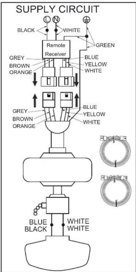
text_image
SUPPLY CIRCUIT BLACK WHITE GREEN Remote Receiver GREY BROWN ORANGE BLUE YELLOW WHITE GREY BROWN ORANGE BLUE YELLOW WHITE BLUE BLACK WHITE WHITEFigure 12
6. Making the Electrical Connections
Finishing the Fan Installation
STANDARD CEILING MOUNTING WARNING ____
WHEN USING THE STANDARD BALL/DOWNROD MOUNTING, THE TAB IN THE RING AT THE BOTTOM OF THE MOUNTING PLATE MUST REST IN THE GROOVE OF THE HANGER BALL. FAILURE TO PROPERLY SEAT THE TAB IN THE GROOVE COULD CAUSE DAMAGE TO WIRING.
- Align the locking slots of the ceiling canopy with the two screws in the mounting plate. Push up to engage the slots and turn clockwise to lock in place. Immediately tighten the two mounting screws firmly.
- Install the remaining two mounting screws into the holes in the canopy and tighten firmly.
- Install the decorative canopy ring by aligning the ring's slots with the screws in the canopy. Rotate the ring counterclockwise to lock in place.
- You may now proceed to attaching the fan blades.
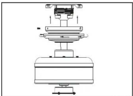
natural_image
Technical line drawing of a mechanical assembly with no visible text or symbolsFigure 14
Attaching the Fan Blades
Note: Your fan blades are reversible. Select the blade finish which best accentuates your decor.
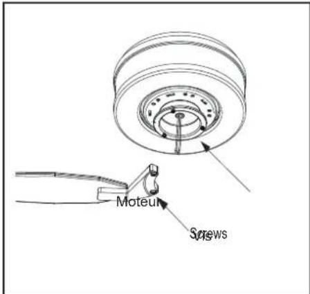
- Attach blade to blade bracket using the screws as shown in figure 15. Start a screw into the bracket. Repeat for the two remaining screws.
- Tighten each screw securely.
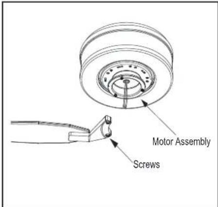
- Fasten the blade assembly to the motor by inserting the alignment post into the slot on the bottom of the motor and tightening the motor screws. Please note that the motor screws are pre-attached into the blade brackets (Figure 16).
- Repeat steps 1, 2 and 3 for the remaining blades.
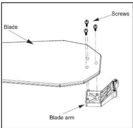
text_image
Blade Screws Blade armFigure 15
text_image
Motor Assembly ScrewsFigure 16
Blade Balancing
All blades are grouped by weight. Because materials vary in density, the fan may wobble even though the blades are weight matched.
The following procedure should correct most fan wobble. Check after each step.
- Check that all blade screws are secure.
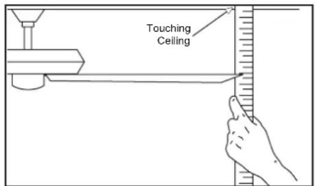
- Most fan wobble problems are caused when blade levels are unequal. Check this level by selecting a point on the ceiling above the tip of one of the blades. Measure from a point on the center of each blade to the point on the ceiling. Measure this distance as shown in Figure 17. Rotate the fan until the next blade is positioned for measurement. Repeat for each blade. Measurements deviation should be within 1/8". Run the fan for 10 minutes.
- Make sure that canopy is tightened securely to ceiling mounting bracket and that the ceiling mounting bracket is tightened securely to the electrical box.
- Interchanging two adjacent blades can redistribute the weight and possibly result in the smoother operation.
- Use the enclosed Blade Balancing Kit if the blade wobble is still noticeable.
text_image
Touching CeilingFigure 17
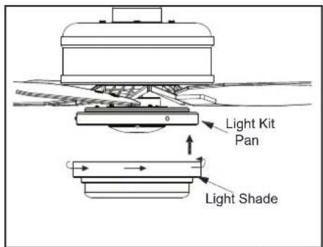
Installing the Light Kit Pan/Light Kit Fitter Assembly/ Light Shade
CAUTION - To reduce the risk of electrical shock, disconnect the electrical supply circuit to the fan before installing the light kit.
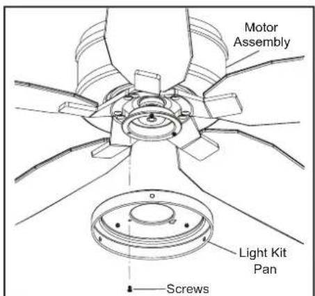
- Loosen but do not remove two of three mounting screws from the fan motor assembly; Remove one mounting screw. (Figure 18)
- Push the light kit pan up to the fan motor assembly so that the two loosened screw heads fit into the keyhole slots. Turn the light kit pan clockwise, and tighten the screws. Re-install the screw that was removed in step 1 and tighten firmly. (Figure 18)
-
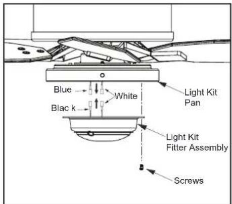
Remove one screw from the light kit pan, and loosen but do not remove the other two screws. Connect the wires from the light kit fitter assembly to the wires from the fan motor assembly by connecting the molded adaptor plugs together. Carefully tuck all wires and splices into the switch cap. (Figure 19)
-
Push the light kit fitter assembly up so that the two loosened screw heads fit into the keyhole slots. Turn the light kit fitter assembly clockwise, tighten the screws. Re-install the screw that was removed in step 3 and tighten firmly. (Figure 19)
- Place the light shade into the light kit pan, aligning the three flat areas on the top of the light shade with the three raised dimples in the light kit pan. Turn the light shade clockwise until it stops. (Figure 20)
NOTE-
PERIODICALLY CHECK THE GLASS SHADE IS SEATED FULLY CLOCKWISE IN THE LIGHT KIT PAN ASSEMBLY.
text_image
Motor Assembly Light Kit Pan ScrewsFigure 18
text_image
Blue White Light Kit Pan Blac k Light Kit Fitter Assembly ScrewsFigure 19
text_image
Light Kit Pan Light ShadeFigure 20
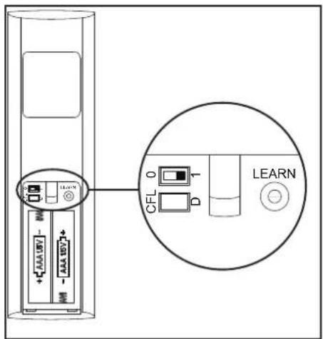
Preparing the Remote Control
NOTE: The remote control has already been paired to the ceiling fan for your convenience. If you have two of the same model fans in your home, please follow the steps below to control each fan independently.
-
Remove the battery cover by pressing firmly on the arrow and sliding the cover off.
-
Install two 1.5V AAA batteries (included).
-
Slide the dip switch in the battery compartment to the "1" setting.
-
Confirm that the power to the fan is off at either the wall switch or breaker box.
-
Return power to the fan at the wall switch or breaker box.
-
Press and release the "Learn" button located in the remote's battery compartment within 30 seconds of turning on the power.
-
If pairing is successful, the fan's light kit will flash and the blades will begin to spin.
-
Replace the battery cover on the remote control.
text_image
Diagram showing a device with labeled ports and an inset circular view highlighting a CFL component labeled 'LEARN'.Figure 21
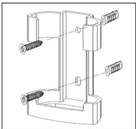
Mounting the remote control holder
NOTE: Screw wall anchors are included for extra support. The included screws are designed to screw easily into the wall. If you would like a more permanent or secure hold, install the wall anchors prior to attaching the wall cradle to the wall.
- Position the wall cradle in the desired position and attach it to the wall using the included wall cradle screws. (Figure 22)
natural_image
Technical line drawing of a mechanical clamp or bracket assembly with screws and pins (no text or symbols)Figure 22
10. Remote Control
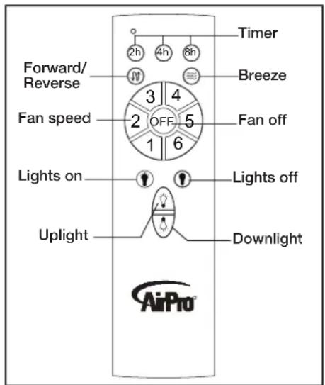
Remote Control
Timer:
While the fan is on press 2h - turns on a 2 hour run timer.
While the fan is on press 4h - turns on a 4 hour run timer.
While the fan is on press 8h - turns on an 8 hour run timer.
Forward/Reverse:
Changes direction of ceiling fan.
Breeze:
Press and release this button to enable the Breeze function, this will change your fan speed randomly, simulating a relaxing breeze.
Fan speed:
LEDs on the fan speed button will illuminate to the corresponding speed.
Press and release 1: turns the fan speed to 1.
Press and release 2: turns the fan speed to 2.
Press and release 3: turns the fan speed to 3.
Press and release 4: turns the fan speed to 4.
Press and release 5: turns the fan speed to 5.
Press and release 6: turns the fan speed to 6.
Fan OFF:
Turns fan Off
Lights ON/OFF
Press and release the lights on button to turn both lights on to the last setting.
Press and release the lights off button to turn both lights off.
Uplight/Downlight Control:
Up Light: Press and release the button to turn the up light on/off. Press and hold the button to activate dimming function and release once the desired brightness level is reached.
Down Light: Press and release the button to turn the down light on/off. Press and hold the button to activate dimming function and release once the desired brightness level is reached.
text_image
Timer Forward/Reverse 2h 4h 8h 3 4 Fan speed OFF 5 1 6 Fan off Lights on Lights off Uplight Downlight AirProFigure 23
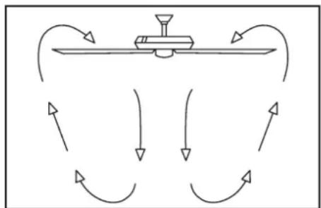
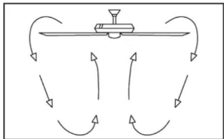
Warm weather - (Forward) A downward air flow creates a cooling effect as shown in Figure 24. This allows you to set your air conditioner on a higher setting without affecting your comfort.
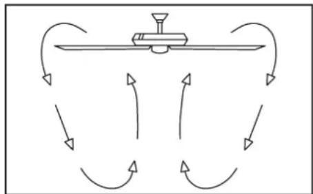
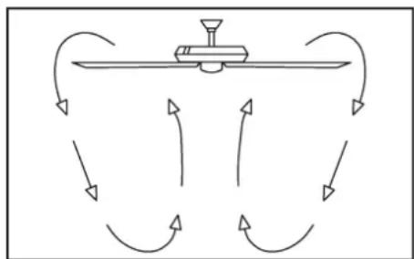
Cool weather - (Reverse) An upward air flow moves warm air off the ceiling are as shown in Figure 25. This allows you to set your heating unit on a lower setting without affecting your comfort.
flowchart
graph TD
    A["Central Device"] --> B{Flow Direction}
    B --> C["Return to Left"]
    B --> D["Return to Right"]
    B --> E["Return to Bottom"]
    B --> F["Return to Left"]
    B --> G["Return to Right"]
Figure 24
flowchart
graph TD
    A["Central Device"] --> B{Return Path}
    B --> C["Left Arrow"]
    B --> D["Right Arrow"]
    B --> E["Left Arrow"]
    B --> F["Right Arrow"]
    B --> G["Bottom Arrow"]
    B --> H["Left Arrow"]
    B --> I["Right Arrow"]
Figure 25
11. Operating Your Fan
Care of Your Fan
Here are some suggestions to help you maintain your fan.
- Because of the fan's natural movement, some connections may become loose. Check the support connections, brackets, and blade attachments twice a year. Make sure they are secure. (It is not necessary to remove fan from ceiling.)
- Clean your fan periodically to help maintain its new appearance over the years. Do not use water when cleaning, this could damage the motor, or possibly cause an electrical shock. Use only a soft brush or lint-free cloth to avoid scratching the finish. The plating is sealed with a lacquer to minimize discoloration or tarnishing. Warning - Make sure the power is off before cleaning your fan.
- You can apply a light coat of furniture polish to the wood for additional protection and enhanced beauty. Cover small scratches with a light application of shoe polish.
- There is no need to oil your fan. The motor has permanently lubricated sealed ball bearings.
Troubleshooting
Problem
Fan will not start
Solution
- Check main and branch circuit fuses or breakers
- Check line wire connections to the fan and switch wire connections in the switch housing. CAUTION: Make sure main power is off.
- Check batteries in the transmitter. Does the red LED light come on? Are you standing close enough to the fan? (Normal range is 10-20 feet.) Are the dip switch settings the same on the transmitter (hand unit) and receiver? REMEMBER TO TURN OFF POWER SUPPLY BEFORE CHECKING THE DIP SWITCH SETTINGS IN RECEIVER.
Fan sounds noisy
- Make sure all motor housing screws are snug.
- Make sure the screws that attach the fan blade bracket to the motor hub are tight.
- Make sure wire nut connections are not rattling against each other or the interior wall of the switch housing. CAUTION: Make sure power is off.
- Allow a 24-hour “breaking in” period. Most noises associated with a new fan disappear during this time.
- If using the Ceiling Fan light kit, make sure the screws securing the glassware are tight. Check that the light bulb is also secure.
- Make sure the canopy is a short distance from the ceiling. It should not touch the ceiling.
- Make sure your electrical box is secure and rubber isolator pads were used between the mounting bracket and electrical box.
WARNING
MAKE SURE THE POWER IS OFF AT THE ELECTRICAL PANEL BOX BEFORE YOU ATTEMPT TO MAKE ANY REPAIRS. REFER TO THE SECTION, "MAKING ELECTRICAL CONNECTIONS."
12. Care of Your Fan and Troubleshooting
| FAN SIZE | SPEED VOLTS | FAN POWER CONSUMPTION (WITHOUT LIGHTS) WATTS | AIRFLOW CFM | AIRFLOW EFFICIENCY (HIGHER IS BETTER) CFM/WATT | NET WEIGHT | GROSS WEIGHT | CUBE FEET | |
| 54” | Low | 1209.73 647 | 2.27 2317 | 1020.7 | 17.42 Lbs | 19.62 Lbs | 1.72 | |
| High 2 | 7 217.86 | |||||||
This equipment has been tested and found to comply with the limits for a Class B digital device, pursuant to Part 15 of the FCC Rules. These limits are designed to provide reasonable protection against harmful interference in a residential installation. This equipment generates, uses and can radiate radio frequency energy and, if not installed and used in accordance with the instructions, may cause harmful interference to radio communications. However, there is no guarantee that interference will not occur in a particular installation. If this equipment does cause harmful interference to radio or television reception, which can be determined by turning the equipment off and on, the user is encouraged to try to correct the interference by one or more of the following measures:
--Reorient or relocate the receiving antenna.
--Increase the separation between the equipment and receiver.
--Connect the equipment into an outlet on a circuit different from that to which the receiver is connected.
--Consult the dealer or an experienced radio/TV technician for help.
CAUTION:
Any changes or modifications not expressly approved by the grantee of this device could void the user's authority to operate the equipment.
This device complies with Part 15 of the FCC Rules. Operation is subject to the following two conditions: (1) This device may not cause harmful interference, and (2) this device must accept any interference received, including interference that may cause undesired operation.
©2017 Progress Lighting, Inc.
701 Millennium Blvd.,
Greenville, SC 29607
All Rights Reserved
13. Specifications
AirPro®
PROGRESS LIGHTING™
natural_image
Line drawing of a multi-panel office ceiling fan with blades and top mount (no text or symbols)93133624_A
P250061
natural_image
Illustration of four different tools: screwdriver, pliers, screwdriver with nut, and wrench (no text or symbols)Opciones de montaje
text_image
Standard mountingFigura 9
natural_image
Technical diagram of a mechanical assembly with a magnified inset showing internal components (no text or labels)Figura 11
natural_image
Technical line drawing of a mechanical assembly with no visible text or symbolsFigura 14
text_image
Diagram showing a device with labeled ports and an inset view of a CFL device labeled 'LEARN'Figura 21
natural_image
Technical line drawing of a mechanical clamp or bracket assembly with two screws and a base (no text or symbols)Figura 22
10. Control remoto
Control remoto
Temporizador:
flowchart
graph TD
    A["Central Device"] --> B{Flow Direction}
    B --> C["Return to Left"]
    B --> D["Return to Right"]
    B --> E["Return to Bottom"]
    B --> F["Return to Left"]
    B --> G["Return to Right"]
Figura 24
flowchart
graph TD
    A["Central Device"] --> B{Flow Direction}
    B --> C["Return Path"]
    B --> D["Return Path"]
    B --> E["Return Path"]
    B --> F["Return Path"]
    B --> G["Return Path"]
    B --> H["Return Path"]
    B --> I["Return Path"]
    B --> J["Return Path"]
    B --> K["Return Path"]
Figura 25
©2017 Progress Lighting, Inc.
701 Millennium Blvd.,
Greenville, SC 29607
natural_image
Line drawing of a multi-panel office ceiling fan with blades and top mount (no text or symbols)93133624_A
P250061
natural_image
Simple line drawing of a remote control with a device and cable (no text or symbols)
natural_image
Two identical coiled wire or coil structures with mounting brackets (no text or symbols)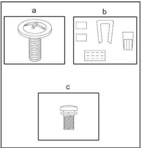
natural_image
Three technical diagrams labeled a, b, and c showing different mechanical or electrical component layouts (no text or symbols present)Outils requis
natural_image
Illustration of four different tools: screwdriver, pliers, screwdriver with base, and wrench (no text or symbols)text_image
Dessenz make for Nike Res. Retirez Do Not RemoveFigure 6
text_image
InStabilized mountingFigure 9
natural_image
Technical diagram of a mechanical assembly with a magnified inset showing internal components (no text or labels)Figure 11
natural_image
Technical line drawing of a mechanical assembly with no visible text or symbolsFigure 14
text_image
Pale Sisews Support de paleFigure 15
text_image
Diagram showing a device with labeled ports and an inset circular view highlighting a CFL component labeled 'LEARN'.Figure 21
natural_image
Technical line drawing of a mechanical clamp or bracket assembly with multiple screw fasteners (no text or labels)Figure 22
10. Télécommande
Télécommande
Minuterie :
flowchart
graph TD
    A["Central Device"] --> B{Flow Direction}
    B -->|Upward Arrows| C["Downward Arrows"]
    B -->|Downward Arrows| D["Rightward Arrows"]
    B -->|Leftward Arrows| E["Leftward Arrows"]
    C --> F["Upward Arrows"]
    D --> G["Downward Arrows"]
    E --> H["Rightward Arrows"]
Figure 24
flowchart
graph TD
    A["Central Device"] --> B{Return Path}
    B --> C["Left Arrow"]
    B --> D["Right Arrow"]
    B --> E["Left Arrow"]
    B --> F["Right Arrow"]
    B --> G["Bottom Arrow"]
    B --> H["Left Arrow"]
    B --> I["Right Arrow"]
Figure 25
©2017 Progress Lighting, Inc.
701 Millennium Blvd.,
Greenville, SC 29607