
Kiln - Pizza oven Everdure - Free user manual and instructions
Find the device manual for free Kiln Everdure in PDF.

User questions about Kiln Everdure
0 question about this device. Answer the ones you know or ask your own.
Ask a new question about this device
Download the instructions for your Pizza oven in PDF format for free! Find your manual Kiln - Everdure and take your electronic device back in hand. On this page are published all the documents necessary for the use of your device. Kiln by Everdure.
USER MANUAL Kiln Everdure
text_image
QR code image containing encoded data, no visible human-readable textScan for further support

Intertek
5024915
CONTENTS
Important Safety Instructions 4
Appliance Details 4
Outdoor Installation Guide....6
Operating Instructions 8
Cooking Hints & Tips KILN S Series - 1 Burner....9
Cooking Hints & Tips KILN R Series - 2 Burner....10
Care & Maintenance 11
Troubleshooting....13
Specifications 14
Note; In this instruction manual, the Everdure Kiln will be referred to as an appliance.
1 BURNER
GRAPHITE
EKILN1GUS
EKILN1GUSNG

1 BURNER
STONE
EKILN1SUS
EKILN1SUSNG

1 BURNER
TERRACOTTA
EKILN1TUS
EKILN1TUSNG
2 BURNER
GRAPHITE
EKILN2GUS
EKILN2GUSNG

2 BURNER
STONE
EKILN2SUS
EKILN2SUSNG

2 BURNER
TERRACOTTA
EKILN2TUS
EKILN2TUSNG

WARNING
CALIFORNIA PROPOSITION 65 WARNING
(a) Handling the brass material on this product exposes you to lead, a chemical known to the State of California to cause cancer and birth defects or other reproductive harm. Wash your hands after handling.
(b) This product contains chemicals, including lead and compounds, a chemical known to the State of California to cause cancer, reproductive harm, or other birth defects.
(c) Propane Warning: Fuels used in liquified propane gas appliances, and the products of combustion of such fuels, can expose you to chemicals including benzene, which is known to the State of California to cause cancer and cause birth defects or other reproductive harm.
(d) Wash your hands after using this product.
For more information, go to: www.P65warnings.ca.gov

DANGER
If you smell gas:
- Shut off gas to the appliance.
- Extinguish any open flame.
- If odour continues, keep away from the appliance and immediately call your fire department.
Failure to follow this instruction could result in fire or explosion, which could cause property damage, personal injury, or death.

DANGER
- Never operate this appliance unattended.
- This appliance shall not be located or used under overhead, unprotected, combustible construction.
- Never operate this appliance within 10ft (3.0m) of any structure, combustible material, or other gas cylinders.
- Never operate this appliance within 24.5ft (7.5m) of any flammable liquid.
- If a fire should occur, keep away from the appliance and immediately call your fire department. Do not attempt to extinguish an oil or grease fire with water.
text_image
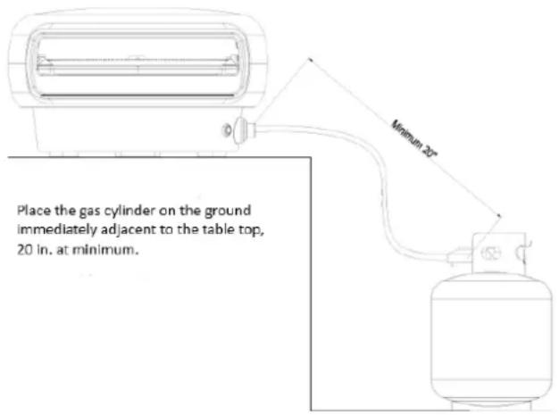
Place the gas cylinder on the ground immediately adjacent to the table top, 20 in. at minimum. Minimum 20°Always check the gas hose and regulator for leaks before use. If there is evidence of abrasion, wear, cuts, or leaks, the hose must be replaced prior to the appliance being put into operation. The replacement hose assembly shall be that specified by the manufacturer.
This appliance is not intended for commercial use.
Grill appliances must conform with local codes or, in the absence of local codes, with the National Fuel Gas Code, ANSI Z223.1/NFPA 54, Storage and Handling of Liquefied Petroleum Gases, ANSI/NFPA 58; or Natural Gas and Propane Installation Code, CSA B149.1; Propane Storage and Handling, CSA B149.2; or the Standard for Recreational Vehicles, ANSI A119.2/NFPA 1192; and Recreational Vehicle Code, CSA Z240 RV Series, as applicable.
When utilizing the power adaptor, the appliance shall be electrically grounded in accordance with local codes or, in the absence of local codes, with the National Electrical Code, ANSI/NFPA 70, or the Canadian Electrical Code CSA C22:1.
Keep the electrical supply cord and the fuel supply hose away from any heated surface(s).
Appliance must be a minimum of 1ft (0.30m) away from any combustible wall surface.
WHEN USING AND COOKING IN YOUR EVERDURE KILN OVEN
Do NOT leave the main burner on HIGH setting for over 30 minutes after ignition. Please refer to COOKING HINTS and TIPS KILN S/R SERIES page in the instruction manual on preheating, cooking and after cooking instructions.
IMPORTANT SAFETY INSTRUCTIONS:
This instruction manual contains important information necessary for the proper assembly and safe use of the appliance. Read and follow all warnings and instructions before assembling and using the appliance.
Follow all warnings and instructions when using the appliance.
Keep this manual for future reference.

DO NOT operate this appliance before reading the instruction booklet.
DO NOT place articles on or against this appliance.
DO NOT store chemical or flammable materials or spray aerosols near this appliance.
DO NOT operate this appliance indoors.
- WARNING: accessible parts may be very hot.
- Use outdoors only.
- Keep away from young children.
- Do not move appliance during use.
- Ensure the gas supply is turned off at the cylinder after use.
- Do not modify this appliance.
- Parts sealed by the manufacturer or agent must not be manipulated by the user.
- Always use protective gloves when handling hot components.
- Storage of an appliance indoors is only permissible if the cylinder is disconnected and removed from the appliance. When the appliance is not used for a period of time, it should be stored in a dry dust-free environment.
- CAUTION: All cleaning and maintenance should be carried out when the oven is cool and with the gas cylinder disconnected.
- BEFORE USE CHECK APPLIANCE AND CONNECTIONS FOR LEAKS: Never check for leaks with a naked flame; always use a soapy water solution. Leak testing: Leak test each time a new gas tank is connected or after a long period without having used the oven. Make sure that the valve is in the correct alignment. Make sure that the hose has no cracking or splitting.

IMPORTANT: If you cannot stop a gas leak, turn off the gas tank valve and call your local gas tank provider.
- The appliance must be kept away from any flammable materials during use.
- When changing the gas cylinder, ensure that the oven is turned to the off position, disconnect the regulator from the gas cylinder and remove the cylinder. Throughout this process, ensure that the cylinder is kept a minimum of 1 meter away from the oven to avoid ignition risks.
- Always turn off the gas cylinder after use.
APPLIANCE DETAILS:
| NAME | MODEL DESIGNATION | COLOR BURNERS COUNTRY | GAS CATEGORY | OUTPUT | INJECTOR SIZE (mm) | HOSE | ||
| EKILN1 | EKILN1GUS Graphite | 1 | USA / CAN | ULPG 2740Pa | 1*23600Btu/Hr 1.48 | 3.93ft / 1200mm | ||
| EKILN1SUS Stone | ||||||||
| EKILN1TUS Terracotta | ||||||||
| EKILN2GUSNG Graphite | NG 1000Pa | 1*22000Btu/Hr 2.42 | 6.67ft / 2000mm | |||||
| EKILN2SUSNG Stone | ||||||||
| EKILN2TUSNG Terracotta | ||||||||
| EKILN2 | EKILN1GUS Graphite | 2 | ULPG 2740Pa | 1*23600Btu/Hr 1*1850Btu/Hr | 1.48/0.4 | 3.93ft / 1200mm | ||
| EKILN1SUS Stone | ||||||||
| EKILN1TUS Terracotta | ||||||||
| EKILN2GUSNG Graphite | NG 1000Pa | 1*22000Btu/Hr 1*1730Btu/Hr | 2.42/0.60 | 6.67ft / 2000mm | ||||
| EKILN2SUSNG Stone | ||||||||
| EKILN2TUSNG Terracotta | ||||||||
| PRODUCT DETAILS METRIC EKILN1 EKILN2 | |||
| Dimensions | mm 740 × 660 × 380 740 × 660 × 380 | ||
| inch | 29.1 × 26.0 × 15.0 | 29.1 × 26.0 × 15.0 | |
| Weight | kg | 26.5 / 33.3 | 29.2 / 35.0 |
| lbs | 58.43 / 73.41 | 64.37 / 77.16 | |
FOR PROPANE CYLINDER CONNECTION:
- To achieve the optimum performance from your appliance, an approved gas cylinder/ bottle must be used. The supplied hose and/or regulator must first be connected to the appliance inlet.
- Do not connect a gas cylinder/ bottle to a appliance that is not secured in the supplied stand or on a stable raised surface. The cylinder should be lower than the appliance, in a protected place on a stable surface.
- Before connecting the gas supply, take care that all gas control knobs are in the off position. Once connected, turn the regulator handle on to turn on the gas supply. Check all joints are secure.
NOTE: Only one gas cylinder should be stored on the stand at any one time.
LEAK TESTING
- Make sure the gas control knob is Off and turn the cylinder valve On.
- Check for leaking joints by brushing with a solution of half-liquid detergent and half-water. If a leak is present, bubbles will appear (or you may hear a hissing sound). Retightening connections can generally repair a leaking joint. You must also check the gas hose and connection at the gas cylinder. If a leak cannot be resolved, do not proceed and turn the gas cylinder/bottle valve off.

DO NOT USE NAKED FLAME FOR LOCATING GAS LEAKS.
IF A LEAK PERSISTS CALL AN AUTHORIZED GAS FITTER.
SPECIAL INSTRUCTIONS FOR THE USE OF REGULATOR AND PROPANE CYLINDER
GAS HOOK-UP: Only the pressure regulator and hose assembly supplied with the appliance should be used. Any replacement pressure regulator and hose assembly must be specified by the appliance manufacturer. This appliance is configured for Liquid Propane. Do not use a Natural Gas supply.
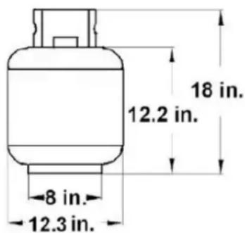
LIQUID PROPANE CYLINDER REQUIREMENTS: (The LP cylinder must be a 20-lb). A dented or rusty Liquid Propane cylinder may be hazardous and should be checked by your supplier. Never use a cylinder with a damaged valve. The Liquid Propane cylinder must be constructed and marked in accordance with the specifications for Liquid Propane cylinders by the United States Department of Transportation (DOT) or the National Standard of Canada, CAN/CSA-B339, Cylinders, Spheres and Tubes for Transportation of Dangerous Goods Commission. The 20-lb cylinder must have a shut off valve terminating in a valve outlet specified, as applicable, for connection type QCC1 in the standard for compressed gas cylinder valve outlet and inlet connection ANSI/CGA-V-1. Storage of an outdoor cooking gas appliance indoor is permissible only if the cylinder is disconnected and removed from the outdoor cooking gas appliance. The cylinder system must be arranged for vapor withdrawal. The cylinder must include a collar to protect the cylinder valve. Manifold pressure: (operating) 11 inches water column (W.C.), (non-operating) 11.2 inches water column (W.C.). The Liquid Propane cylinder must be fitted with an Overfill Protection Device (OPD). Remove the plastic valve cover from the Liquid Propane cylinder is placed into the cart.
text_image
18 in. 12.2 in. 8 in. 12.3 in.CONNECTING THE LIQUID PROPANE CYLINDER:
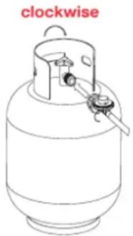
To connect the Liquid Propane gas supply cylinder: The cylinder valve should be in the "OFF" position. If not, turn the valve clockwise until it stops. Make sure the cylinder valve has the proper type-1 external male thread connections per ANSI Z211.81. Make sure the burner valves are in the "OFF" position. Inspect the valve connections, port and regulator assembly to the valve, and use your hand to tighten the nut clockwise until it stops. The use of a wrench could damage the quick coupling nut and result in a hazardous situation, open the cylinder valve fully by turning the valve anti-clockwise. Before lighting the appliance, use a soap and water solution to check all the connections for leaks. If a leak is found, turn the cylinder valve "OFF" and do not use the appliance until a local Liquid Propane dealer can make repairs.
natural_image
Line drawing of a cylindrical gas cylinder with a side-mounted valve and a label 'clockwise' in red (no other text or symbols)WARNING:
- Do not store a spare LP gas cylinder under or near this appliance.
- Never fill the cylinder beyond 80 percent full.
- If the information in items 1&2 is not followed exactly, a fire causing death or serious injury may occur.
CAUTION: Place dust cap on cylinder valve outlet whenever the cylinder is not in use. Only install the type of dust cap on the cylinder valve outlet that is provided with the cylinder valve. Other types of caps or plugs may result in leakage of propane.
OUTDOOR INSTALLATION GUIDE
This appliance shall only be used in an above-ground open-air situation with natural ventilation, without stagnant areas, where gas leakage and products of combustion are rapidly dispersed by wind and natural convection. This appliance must not be used indoors. Do not use your appliance in garages, porches, sheds, or other enclosed areas. The appliance is not intended to be installed in or used on recreational vehicles (e.g., boats, trucks, and tents) and should not be placed close to or under any surfaces that will burn or are sensitive to heat. Do not block/ obstruct the flow of air and combustion around the appliance housing while in use.
Battery Installation:
Unscrew the pulse igniter cap to fit one new AA battery note the (+) and (−) marking and refit the cap.
KILN R Series - 2 Burner
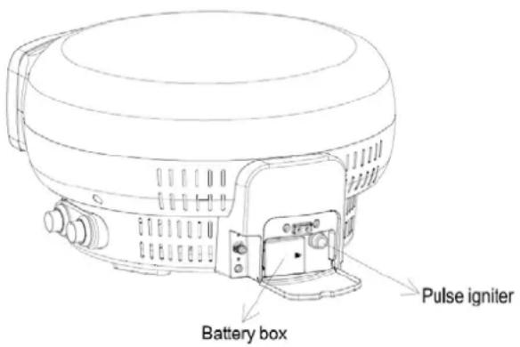
Remove the battery compartment cover. Load a set of four new AA type batteries so that their plus (+) and minus (−) ends are facing as indicated by the markings. Refit battery compartment cover.
text_image
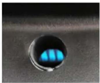
Battery box Pulse igniterBOOST BURNER INSPECTION HOLE
ON OFF
natural_image
Close-up of a blue-tinted circular object with internal blue highlights, mounted on a dark surface (no text or symbols visible)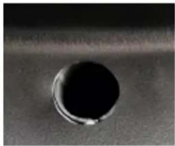
natural_image
Close-up of a circular hole on a textured surface (no text or symbols visible)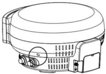
natural_image
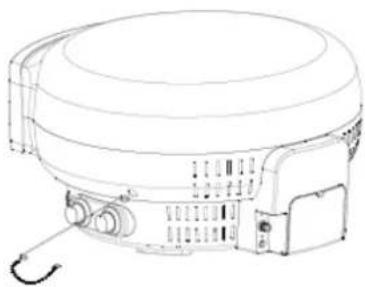
Line drawing of a cylindrical device with internal components and ventilation slots (no text or symbols)Visual inspection hole to check whether the boost burner flame is on or off.
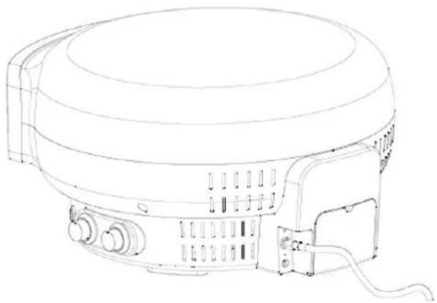
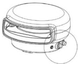
FITTING GAS HOSE
- Make sure the burner knob is turned off before connecting the gas hose.
- Connect the gas hose to the appliance.
natural_image
Line drawing of a portable electric stove or appliance with control panel and wiring (no text or symbols)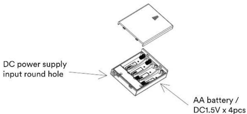
text_image
DC power supply input round hole AA battery / DC1.5V x 4pcsOPERATING INSTRUCTIONS:
Once your regulator is connected, open the gas from your gas cylinder.
First-time use
It is highly recommended prior to cooking on your appliance for the first time that you conduct a burn-off. Turn the main burner on high for 30 minutes. Then turn off the main burner and let the oven cool down naturally. Once the appliance has cooled, use a paper towel to wipe the inside of the appliance to remove any soot from the burn-off. Be careful the oven may still be hot in some places.
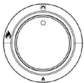
KILN S Series - 1 Burner
To ignite the burner, push the knob in and slowly turn it anti-clockwise until you hear a click of the ignition. This should take at least 8-10 seconds as you allow the gas to flow into the burner inside the appliance. Hold in for another 10 seconds after ignition, then release. Set the burner to your desired requirement. If the burner does not light, leave the knob at OFF and wait 5 minutes before trying again.

natural_image
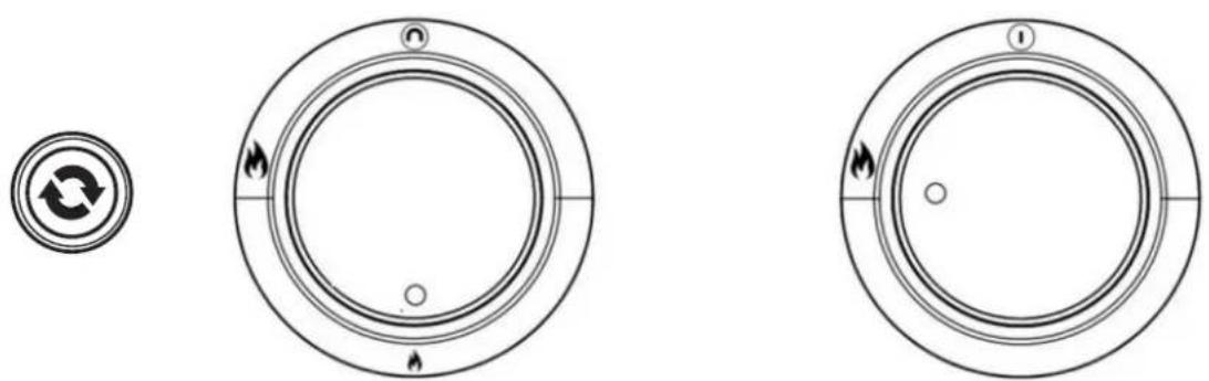
Simple circular diagram with concentric rings and small symbols, no text or labels presentKILN R Series - 2 Burner
To ignite the burners, push the knob in and slowly turn it anti-clockwise until you hear a click of the ignition. This should take at least 8-10 seconds as you allow the gas to flow into the burner inside the appliance. Hold in for another 10 seconds after ignition, then release. Set the burner to your desired requirement. Press the button for the turntable to begin rotating inside the appliance. If the burner does not light, leave the knob at OFF and wait 5 minutes before retrying. WARNING: Do not leave the boost burner activated for an extended period of time without the turntable running, as this may cause damage to the stone.

natural_image
Simple circular diagram with concentric rings and small symbols, no text or labels present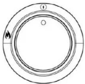
natural_image
Simple circular diagram with concentric rings and a small circle at the center, no text or symbols present.| Symbol Description | |
 | Main burner |
 | Boost burner |
 | Turntable rotation |
natural_image
Line drawing of a cylindrical device with handle and mounting bracket (no text or symbols)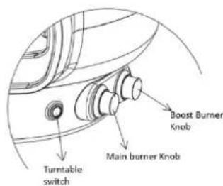
text_image
Turntable switch Main burner Knob Boost Burner KnobCOOKING HINTS AND TIPS KILN S SERIES - 1 BURNER
Preheating
Ignite the appliance and leave it on high for approx. 15 to 20min. This will give you enough time to heat the stone to your desired cooking temperature.
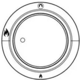
natural_image
Circular diagram with concentric rings and two flame symbols at the bottom (no text or labels)Cooking
When the appliance has reached your desired cooking temperature, turn the knob to halfway.
natural_image
Simple circular diagram with concentric rings and two labeled points, no text or symbols present.After cooking
Once you have cooked on the appliance, just before you go to eat and if you are continuing to cook, turn the main burner down to the low setting. If you have finished cooking on the appliance, turn the main burner off. Running the appliance for an extended period of time with the main burner on the high setting could result in damage to your appliance.
natural_image
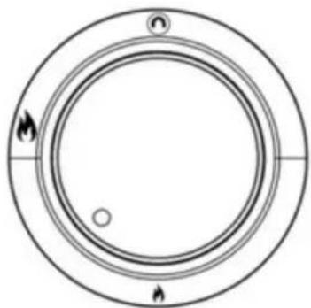
Simple circular diagram with concentric rings and flame symbols at the bottom (no text or labels)COOKING HINTS AND TIPS KILN R SERIES - 2 BURNER
Preheating
Start the turntable by pressing the button. Ignite both burners and leave on high for approx. 10min. This will give you enough time to heat the stone to your desired cooking temperature. Note: the boost burner only has one setting. Don't leave the boost burner on without the turntable rotating.
natural_image
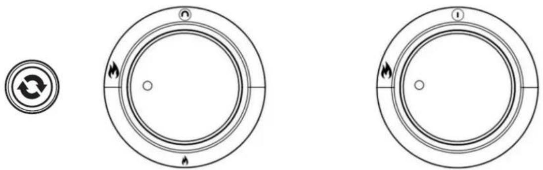
Three circular diagrams with arrows and symbols, no readable text or labelsCooking
When the appliance has reached your desired cooking temperature, turn the main burner knob to halfway.
natural_image
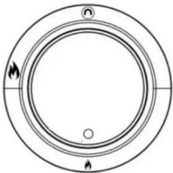
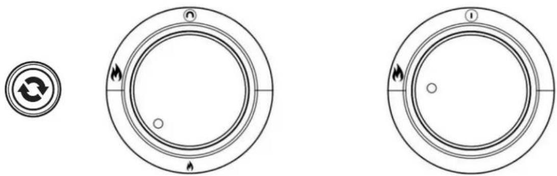
Three circular diagrams with arrows and symbols, no readable text or labelsAfter cooking
Once you have cooked on the appliance, just before you go to eat and if you are continuing to cook more, turn the main burner down to the low setting. If you have finished cooking on the appliance, turn both the main and boost burner off. Running the appliance for an extended period of time with the main burner on high setting could result in damage to your appliance.
natural_image
Three circular diagrams with arrows and symbols, no readable text or labels presentCARE & MAINTENANCE:
EXTERNAL CLEANING
- Before cleaning the exterior, ensure the appliance has cooled and is safe to touch.
- Painted and plastic surfaces can be cleaned using a mild household detergent or cleaner and a clean cloth (do not use scourers or harsh detergents).
- It is advisable to test cleaners on a small section of the appliance first. NEVER use paint thinners or similar solvents for cleaning, and NEVER pour cold water over hot surfaces.
• Dry the surface afterwards.
INTERNAL CLEANING
- Before cleaning the internal parts, ensure the appliance has cooled and is safe to touch.
- The inside of the appliance can be cleaned by using some water, mild detergent and a sponge or mild scouring pad.
- For hard-to-clean areas, use a little baking soda on a wet sponge. DO NOT use abrasive cleaners.
CORDIERITE PIZZA STONE CARE
- This pizza stone is designed to be used in the Everdure Kiln only.
- Only use water to clean the pizza stone. DO NOT submerge in water, using soap will leave residue in the pores of the stone.
- Take care of the pizza stone as it is fragile and could break if bumped or dropped.
- Be careful handling the pizza stone as it can retain heat for many hours after cooking.
• DO NOT cool the stone with water when the stone is hot; this could crack and damage the pizza stone. - After cleaning the pizza stone with water, thoroughly dry the stone before use.
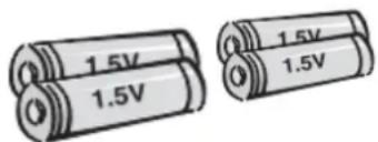
BATTERIES DO'S & DO NOT'S
text_image
1.5V 1.5V 1.5V 1.5V- Dispose of used batteries carefully to ensure that a small child does not consume them. Please seek doctor - medical attention immediately if batteries are consumed.
• DO NOT mix new batteries with old batteries. This may cause the batteries to overheat and leak. - DO NOT place non-rechargeable batteries in a charging device.
• DO NOT disassemble, crush, puncture, or otherwise damage batteries. This can result in leakage or rupture. - DO preserve battery life by switching off a device and removing the batteries when it's not being used and is not expected to be used for extended periods of time.
• DO use the specified type of battery (AA Batteries). - DO insert the batteries properly. Follow the symbols showing the correct way to position the positive (+) and negative (-) ends of the batteries.
- DO immediately remove exhausted batteries from your device and dispose of them properly.
CHECKING THE BURNERS FOR FLAME STABILITY:
Visually check the burner flames for correct function when the unit's operating by inspecting the burner flame/flames with the stone (EKILN R Series - 2 burner only) removed. A good flame should be blue with some yellow tipping.
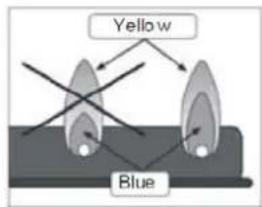
text_image
Yellow BlueNote: take care when viewing the burner operation not to lean into the flame; failure to do this may result in personal injury.
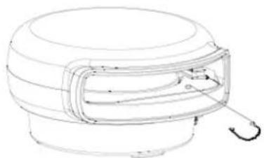
MANUAL IGNITION:
In the instance where the automatic ignition fails, the product can be lit with the provided matchstick holder.
MAIN BURNER:
Using the matchstick holder, carefully ignite the main burner as shown below.
natural_image
Line drawing of a mechanical component with a curved hook and internal structure (no text or symbols)BOOST BURNER:
Using the matchstick holder, carefully ignite the lower burner through the lower burner viewing port. This is only applicable to boost burner models.
natural_image
Line drawing of a cylindrical electronic device with ports and a curved arm (no text or symbols)TROUBLESHOOTING:
Burner will not ignite when using the igniter:
| Cylinder valve is not on Turn cylinder valve on |
| Cylinder is empty Replace with a full cylinder |
| Igniter button is not working Check battery |
| Igniter is not sparking Contact the Service Centre |
Burner flame is erratic:
| Flame is burning inside burner (hissing sound) | Turn off burner, allow to cool and re-ignite |
| Regulator is faulty Contact the Service Centre | |
| Injector is partially blocked | Clean injector with a toothbrush. Do not drill out or use wire.Do not remove the injector. Contact the Service Centre |
Gas is leaking from connections:
| Connections are loose | Tighten loose connections (do not over-tighten) and leak test under pressure with a soapy water solution (page 2) |
| Hose has deteriorated Replace hose (Contact the Service Centre) | |
| Gas valve is faulty Contact the Service Centre | |
| Threads are damaged Contact the Service Centre | |
Turntable not working:
| Turntable not turning | Check that the power cord from the power adaptor is connected correctly and that the power is on at the main power board.Check if batteries are fitted and are properly installed in the battery compartment.Check if batteries are full of charge and replace if needed. |
| Turntable is broken Contact the Service Centre | |
| Switch or wiring damaged Contact the Service Centre | |
SPECIFICATIONS:
| PRODUCT 1 BURNER 2 BURNER | ||
| Dimensions (mm) | 740 × 660 × 380 (mm) 740 × 660 × 380 (mm) | |
| 29.1 × 26.0 × 15.0 (inch) 29.1 × 26.0 × 15.0 (inch) | ||
| Weight NW / GW | 26.5 / 33.3 (kg) 29.2 / 35.0 (kg) | |
| 58.43 / 73.41(lbs) 64.37 / 77.16 (lbs) | ||
| Turntable RPM using the adapter supplied N/A 2.5 rpm | ||
Power supply KILN R Series - 2 Burner
| MODEL SPECIFICATION REMARK | ||
| USA / CAN | Model: GA-0301000Input: AC 100~240V ~50/60Hz 0.6AOutput: 3.0V 1000mA | With plug round hole which match-up with DC005 / 5.5*2.1 pin |
KILN S SERIES - 1 BURNER
NO. PART NAME NO. PART NAME
| 1 Upper lid 15 Base welding bracket | |||
| 2 Lower outer housing 16 1B Valve assembly | |||
| 3 Aluminum fascia 17 Bezel of main burner | |||
| 4 Inner firebox 18 Knob | |||
| 5 Insulation of inner firebox 19 Gas inlet connector | |||
| 6 SS main burner 20 Corrugated pipe | |||
| 7 Ignition pin I 21 Pulse igniter | |||
| 8 | Ignition pin II | 22 | Rear cover |
| 9 | Upper thermocouple | 23 | Aluminum rear seat |
| 10 | Insulation of base | 24 | Control box |
| 11 | T shape pizza stone | 25 | PP foot |
| 12 | Base assembly | 26 | Bottom cover |
| 13 | Pulse igniter wire I | 27 | USA regulator |
| 14 | Pulse igniter wire II | 28 | Match holder |
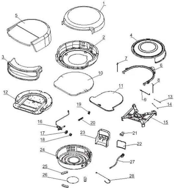
text_image
Exploded view diagram of a mechanical device with numbered parts for identificationKILN R SERIES - 2 BURNER
| NO. | PART NAME | NO. | PART NAME |
| 1 | Upper lid | 26 | Aluminum rear seat |
| 2 | Lower outer housing | 27 | SS support plate |
| 3 | Aluminum fascia | 28 | Bearing support |
| 4 | Inner firebox | 29 | Cardan joint |
| 5 | Insulation of inner firebox | 30 | Motor coupling |
| 6 | SS main burner | 31 | Motor base heat shield |
| 7 | Ignition pin I | 32 | Inner bracket |
| 8 | Ignition pin II | 33 | Aluminum limit plate |
| 9 | Upper thermocouple | 34 | Insulation of motor |
| 10 | Lower thermocouple | 35 | Motor inner cover |
| 11 | Boost burner | 36 | DC motor |
| 12 | Lower ignition pin | 37 | 2B Valve assembly |
| 13 | Lower heat shield | 38 | Bezel of main burner |
| 14 | Insulation of boost burner | 39 | Bezel of boost burner |
| 15 | Pulse igniter wire I | 40 | Knob |
| 16 | Pulse igniter wire II | 41 | Pulse igniter |
| 17 | Base welding bracket | 42 | Control box |
| 18 | 16” Round pizza stone | 43 | Rotary button |
| 19 | Insulation of base | 44 | USA regulator |
| 20 | Base assembly | 45 | Gas inlet connector |
| 21 | Front pizza stone | 46 | Corrugated pipe |
| 22 | Cast iron turntable | 47 | PP foot |
| 23 | Flame viewing pipe | 48 | Bottom cover |
| 24 | Rear cover | 49 | USA adapter |
| 25 | Battery box | 50 | Match holder |
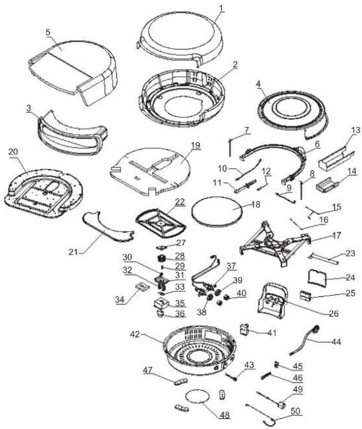
text_image
Exploded view diagram of a smartwatch module with numbered parts for identificationFrançais
CONTENU
text_image
18 in. 12.2 in. 8 in. 12.3 in.RACCORDEMENT DE LA BOUTEILLE DE PROPANE LIQUIDE :
natural_image
Line drawing of a cylindrical gas cylinder with a side outlet and internal components (no text or symbols)AVERTISSEMENT :
natural_image
Close-up of a black hole with a blue illuminated surface, possibly a lens or aperture (no text or symbols visible)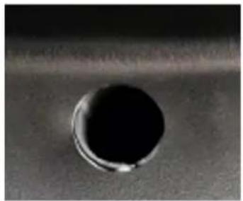
natural_image
Close-up of a dark circular hole on a textured surface (no text or symbols visible)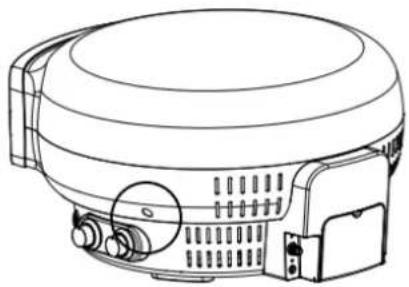
natural_image
Line drawing of a cylindrical appliance with internal components and ventilation slots (no text or symbols)natural_image
Simple circular diagram with concentric rings and two flame symbols at the bottom (no text or labels)natural_image
Simple circular diagram with concentric rings and small symbols, no text or labels present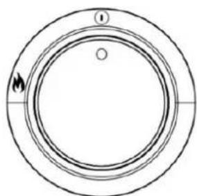
natural_image
Simple circular diagram with concentric rings and a small circle at the center, no text or symbols present.natural_image
Line drawing of a cylindrical device with handle and mounting bracket (no text or symbols)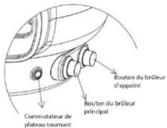
natural_image
Circular diagram with concentric rings and two flame symbols at the bottom (no text or labels)Cuisson
natural_image
Simple circular diagram with concentric rings and two labeled points, no text or symbols present.Après la caisson
natural_image
Circular diagram with concentric rings and flame symbols, no text or labels presentEVERDURE
TRUCS ET ASTUCES DE CUISSON KILN SÉRIE R - 2 BRÛLEURS
F
Préchauffage
natural_image
Three circular diagrams with arrows and symbols, no readable text or labelsCuisson
natural_image
Three circular diagrams with arrows and symbols, no readable text or labelsAprès la caisson
natural_image
Three circular diagrams with arrows and symbols, no readable text or labels presentNETTOYAGE ET ENTRETIEN :
NETTOYAGE EXTÉRIEUR
natural_image
Line drawing of a mechanical device with a curved hook and internal components (no text or symbols)BOOST BRÛLEUR:
natural_image
Line drawing of a cylindrical electronic device with ports and a curved cable (no text or symbols)DÉPANNAGE:
text_image
Exploded view diagram of a smartwatch with numbered parts for identificationLISTE DES PIÈCES EKILN2
NO. NOM DE LA PIÈCE NO. NOM DE LA PIÈCE
text_image
Exploded view diagram of a smartwatch with numbered parts for identificationEVERDURE
FR
EVERDURE
KILN
www.everdure.com
IM REF: EKILN USA 23/05/2023