RBES632 - Range hood Everdure - Free user manual and instructions
Find the device manual for free RBES632 Everdure in PDF.

| Product Type | Range Hood |
| Brand | Everdure |
| Model | RBES632 |
| Width | 60 cm |
| Depth | 50 cm |
| Height (built-in) | 15 cm |
| Weight | 12 kg |
| Power Supply | 220-240 V, 50 Hz |
| Maximum Power Consumption | 150 W |
| Motor Power | 130 W |
| Extraction Rate (max) | 400 m³/h |
| Noise Level (max) | 55 dB |
| Number of Speeds | 3 |
| Lighting | LED, 2 x 3 W |
| Filter Type | Aluminum mesh, washable |
| Duct Diameter | 150 mm |
| Control Type | Touch buttons |
| Installation Type | Built-in under cabinet |
| Material | Stainless steel |
| Maintenance | Clean filters every 2-3 months |
| Safety Features | Overheat protection, auto shut-off |
| Spare Parts Availability | Filters and LED lights available |
| Repairability | Serviceable by qualified technician |
Frequently Asked Questions - RBES632 Everdure
User questions about RBES632 Everdure
0 question about this device. Answer the ones you know or ask your own.
Ask a new question about this device
Download the instructions for your Range hood in PDF format for free! Find your manual RBES632 - Everdure and take your electronic device back in hand. On this page are published all the documents necessary for the use of your device. RBES632 by Everdure.
USER MANUAL RBES632 Everdure
INSTALLATION, OPERATION
& MAINTENANCE INSTRUCTIONS
FOR EVERDURE RANGEHOOD
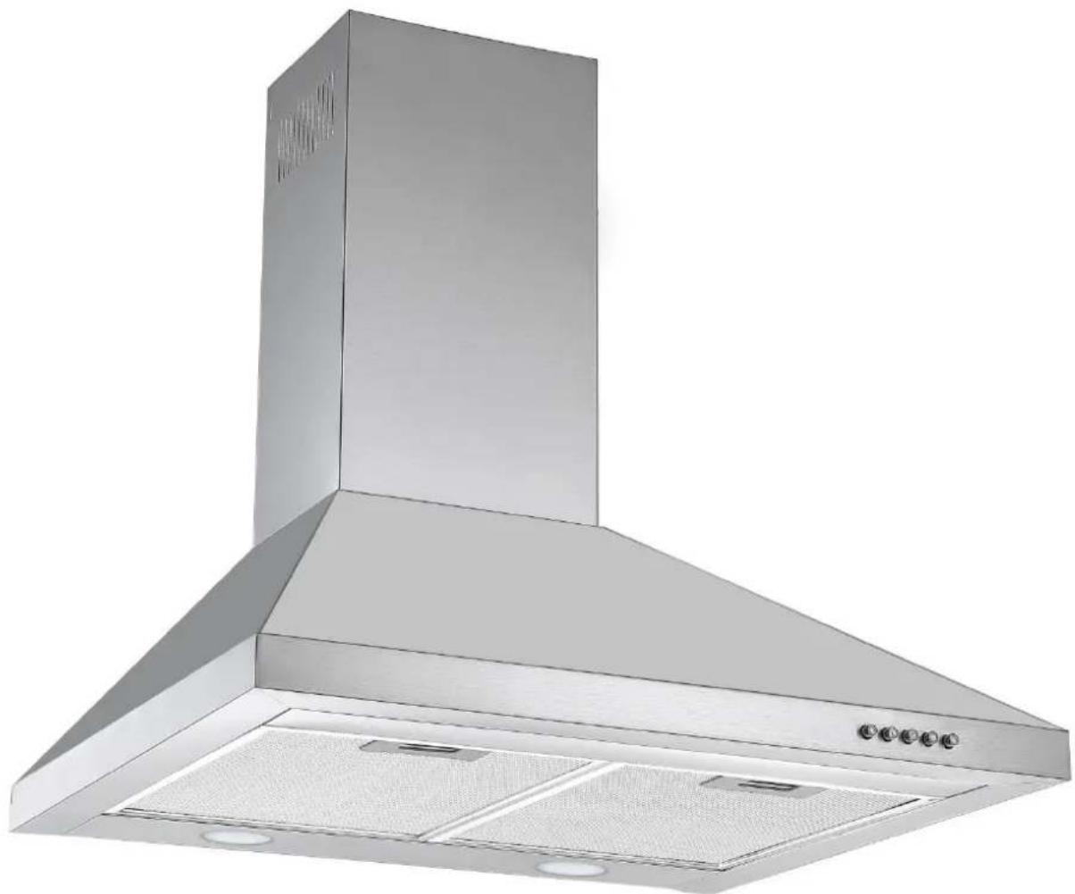
natural_image
Exterior view of a stainless steel kitchen range hood (no text or symbols visible)Pictured: RBES632
Models:
RBES632
RBES632B
RBES912
EVERDURE.
EVERDURE.
INSTALLATION, OPERATION AND MAINTENANCE INSTRUCTIONS FOR EVERDURE RANGEHOODS
RBES632, RBES632B, RBES912
CONGRATULATIONS
Welcome to the Everdure Kitchen Community and thank you for choosing one of our many fantastic cooking appliances. We are confident that you will now be able to meet your cooking needs. Before you use the cooktop we strongly recommend that you read though the whole user manual which provides the description of this product and the proper use of its functions. To avoid the ever-present risks involved with using an electrical appliance it is vital that the appliance is installed correctly and that you read the safety instructions carefully to avoid misuse and hazards.
It is important that you retain these instructions and your proof of purchase along with any other important documents about this product for future reference. Due to continual product development, Everdure reserves the right to alter specifications or appearances without notice.
CONTENTS
IMPORTANT SAFETY INSTRUCTIONS ....1
APPLIANCE DETAILS....2
INSTALLATION INSTRUCTIONS.... 3-4
OPERATING INSTRUCTIONS....5
CLEANING 5
LEDS....6
TROUBLESHOOTING 6
It is important that you retain these instructions, proof of purchase as well as other important documents about this product for future reference.
Due to continual product development, Everdure reserves the right to alter specifications or appearances without notice.
Remove all packaging and dispose responsibly – recycle where facilities are available.
EVERDURE.
IMPORTANT SAFETY INSTRUCTIONS
IMPORTANT: Read the assembly instruction section and safety precautions of this booklet carefully before removing the contents of this carton.
- In certain circumstances electrical appliances may be a safety hazard.
- This appliance is not intended for use by persons (including children) with reduced physical, sensory or mental capabilities, or lack of experience or knowledge, unless they have been given supervision or instruction concerning the use of the appliance by a person responsible for their safety. Young children should be supervised to ensure that they do not play with the appliance.
- Do not check the status of the filters whilst the cooker hood is operating.
- Do not touch the light bulbs after use.
- Do not disconnect the appliance with wet hands.
- Do not disconnect the power supply by pulling on the cable.
- Do not flambé underneath the range hood.
- Avoid free flame, as it may cause damage to the filters and can be a fire hazard.
- Unplug the appliance before carrying out maintenance, cleaning or replacing lamps.
- If the power cord is damaged, it must be replaced by the manufacturer, an authorised service centre or similarly qualified persons to avoid a hazard.
- For indoor use only.
- It is recommended to operate the range hood prior to cooking.
- It is recommended to leave the range hood in operation for 15 minutes after cooking is terminated in order to completely eliminate cooking vapours and odours.
- Turn off the range hood when not in use.
- Do not use the range hood if it is damaged, especially the supply cord and the case.
- Do not immerse the range hood in liquid.
- The exhaust air must not be discharged into a flue which is used for exhausting fumes from an appliance burning gas or other fuels (not applicable to appliances that only discharge the air back into the room).
- Regulations concerning the discharge of air have to be fulfilled.
- There shall be adequate ventilation of the room when the range hood is used at the same time as appliances burning gas of other fuels (not applicable to appliances that only discharge the air back into the room).
- Clean the surface of the cooker hood regularly using a cloth moistened with denatured alcohol or a non-abrasive liquid detergent.
- There is a fire risk if cleaning is not carried out in accordance with the instructions.
- The 600mm units are intended for use above hobs that are 600mm wide and the 900mm units are intended for use above hobs that are 900mm wide.
- The range hood must be mounted at a minimum distance of 65cm above the cooking surface.
- CAUTION: Accessible parts may become hot when used with cooking appliances.
- Warning: Failure to install the screws or fixing device in accordance with these instructions may result in electrical hazards.
APPLIANCE DETAILS
| Voltage & Frequency: | 220-240V 50Hz |
| Lamp Max: | RBES632:2x3W GU10 LEDRBES632B:2x3W GU10 LEDRBES912:2x3W GU10 LED |
| Rated Input Power: | RBES632:196WRBES632B:196WRBES912:196W |
General Information
Before installing and operating the rangehood, carefully read the following important information regarding installation safety and maintenance. Keep this information booklet accessible for further consultations.
The appliance has been designed to exhaust cooking fumes externally. Before installation, please ensure that the following have been supplied and that the tools listed below are readily available.
What is Supplied
• Rangehood (including one-way valve for flue x 1) x 1
• Installation kit x 1:
○ 8mm bolts x 6
- 30mm screws x 2
- 40mm screws x 7
○ plastic plugs x 9
- Mounting brackets x 3
- Instruction booklet x 1
What may be needed for Installation
Electric Drill
- Tape Measure
- Spirit Level
- Screwdrivers
- Duct Tape
- Jig Saw
- Ladder
- Torch (If natural lighting is minimal)
INSTALLATION INSTRUCTIONS
- Please ensure that before installing the rangehood, all power is switched off.
• Installation must be in accordance to the local electrical authority and codes. - This rangehood must be earthed at all times for the operators' safety.
- The switched power outlet for the rangehood should be positioned to enable the user to turn the power off, to enable cleaning and any maintenance required.
- The switched power outlet should be installed within 600mm from the rear of the appliance.
- Ensure that when installing the rangehood, that it is protected from any possible damage from tools etc.
- Ducting for this appliance must be installed in accordance to the local authority.
- Ensure that the fixings used for this rangehood are suitable.
- Check the area where the rangehood is to be fitted, to ensure that it is structurally sound.
• The Everdure RBES632 & RBES912 rangehoods are intended to be installed directly onto a wall.
INSTALLATION OF THE RBES632 & RBES912 RANGEHOODS DIRECTLY TO A WALL
Ensure that the wall is structurally sound, and is capable of carrying the weight of the rangehood.
The rangehood must be placed at a minimum of 650mm away from the cooking surface of an electric cooktop or gas cooktop. The cooktop may require a different minimum distance; the greater minimum distance must be followed. The appliance is held to a wall via 3 brackets (supplied with the appliance):
1) Hook Bracket. 2) Centre Bracket (flat). 3) Top Bracket (U-shaped).
Place the hood main unit (no u-shaped section) against the wall at the correct position and mark off the top edge of the appliance. Remove the main unit and measure up 22mm to get the top level for the hook bracket. Place the hook bracket (hooks up) under the mark and mark in the 3 screw holes. Remove the bracket and drill three (3) ∅8mm holes 100mm apart. Insert plastic plugs into the holes and fix the hook bracket onto the wall (see figure 1) with three (3) 40mm screws. Place the hood main unit onto the hooks.
If the position is correct, mark out the positions for the safety screw holes (through the back of the appliance), and remove the hood body. Drill two (2) ∅8mm holes and fit in two (2) plastic plugs.
Screw the one-way valve in position at the top of the body (4 x 8mm bolts) & fit the soot tube to the one-way valve (see figures 2 & 3).
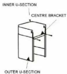
Fit the u-shaped sections together & screw the centre bracket onto the back of the outer u-shaped section using the supplied 8mm screws (this helps keep the width at the back even with the front) (see figure 4). Place the u-shaped section onto the main unit and fix in place with two (2) 8mm screws (see figure 5).
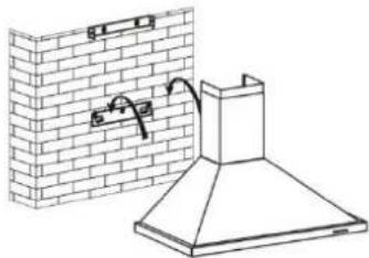
Hook the main unit with the u-shaped sections back onto the wall. Mark the positions of the 2 holes needed to fix the centre bracket to the wall & remove the assembly. Drill two (2) ∅8mm holes and fit in two (2) plastic plugs. Place the assembly back on the hooks. Fix the centre bracket to the wall with two (2) 40mm screws and fix the body to the wall with the 30mm screws (through the back of the main appliance). Run the loose end of the soot tube outside.
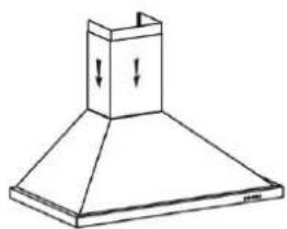
Calculate the final height of the u-shaped section and pull out the inside u-shaped section to a suitable height (see figure 5) to check. Mark the 2 sides near the top and push the inner section out of the way. Place the top bracket (slots to the bottom) centred between the 2 marks, mark the 2 screw holes. Remove the bracket and drill two (2) ∅8mm holes at the marks. Insert plastic plugs into the holes and fix the hook bracket onto the wall (slightly loose) using 40mm screws.
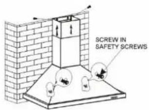
Pull up the inside u-section to allocate the top bracket correctly, and tighten the screws holding the bracket. Pull the u-section over the bracket completely and fix into place with 2 screws at the sides (see figure 7). Note: The top edge of the u-shaped bracket matches the top edge of the u-shaped section – adjust according to your own needs.
For timber framed houses, special care should be taken that all brackets are attached to areas that will support the weight of the rangehood.
NOTE: Remove all protective plastic coatings from the stainless steel surfaces before use.
EVERDURE.
INSTALLATION INSTRUCTIONS
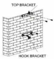
text_image
TOP BRACKET HOOK BRACKETFigure 1
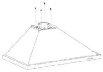
natural_image
Line drawing of a conical structure with three vertical arrows indicating upward motion (no text or symbols)Figure 2
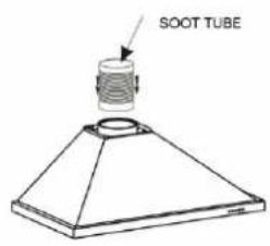
text_image
SOOT TUBEFigure 3
text_image
INNER U-SECTION CENTRE BRACKET OUTER U-SECTIONFigure 4
natural_image
Line drawing of a conical hood with downward arrows indicating compression or force (no text or symbols)Figure 5
natural_image
Technical line drawing of a brick chimney with a mounted hood and wall-mounted fixture (no text or symbols)Figure 6
text_image
SCREW IN SAFETY SCREWSFigure 7
NOTE: Care should be taken that the rangehood is fitted correctly (see diagram below). Incorrect installation can cause a build-up of grease and oils and cause damage to the appliance.
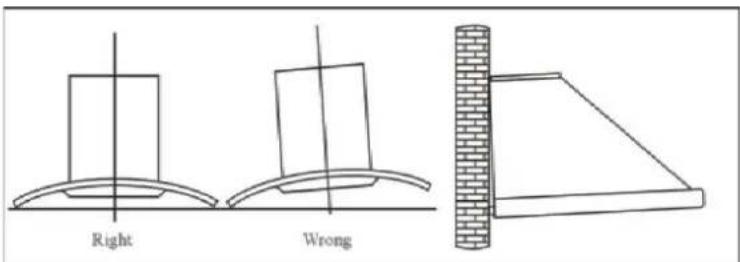
text_image
Right WrongNOTE: Remove all protective plastic coatings from the stainless steel surfaces before use.
OPERATING INSTRUCTIONS
NOTE: Before the appliance can be operated, it must be ducted.
Connect the plug into the power.
FOR RBES632, & RBES912 PUSH BUTTON OPERATED RANGEHOODS
The rangehood has indication diagrams to allow you to easily select the fan operating speed required.
Push the low button, indicated by a fan with 3 blades, and the motor will run at a low speed.
Push the medium button, indicated by a fan with 4 blades and the motor will run at a medium speed.
Push the high button, indicated by a fan with 5 blades and the motor will run at a high speed.
Push stop button, indicated by an (O) and the motor will stop.
Push the light button, indicated by a lit globe and the two lights will come on. Push it again and the light will turn off.
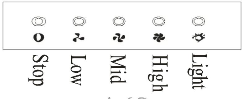
text_image
Stop Low Mid High LightCLEANING
SAFETY PRECAUTION
Before cleaning your rangehood or performing any maintenance, please ensure that the rangehood is turned off at the power point.
Do not use abrasive cleaners to clean the rangehood. The use of warm soapy water and a cloth are recommended.
Ensure that the rangehood is cleaned regularly, as a build-up of grease and fat may occur otherwise.
The filters on the rangehood must be cleaned regularly to maintain efficiency, and prevent grease build up. The filter mesh is made of a high density Stainless Steel. It is recommended that this is undertaken every 4 – 6 weeks, depending on frequency of use. The filters can be cleaned with warm soapy water or a cloth.
Cleaning of the rangehood must be performed as described above; otherwise there is a possibility of a fire hazard due to grease and fat build up.
EVERDURE.
LEDS
Warning: Make sure to switch off the unit, unplug it from the wall socket and ensure the bulb has cooled down before attempting to replace the LED bulb.
- Take out the aluminium filter and screw out the bulb from the inside of the range hood.
- Replace with the same type of bulb: o Type: GU10
• Max Wattage: 2 x 3W
• Voltage Range: 220 – 240V \~50Hz
• ILCOS D Code: DR-3/65/1B-H-GU10-46/50 - Replace the aluminium filter.
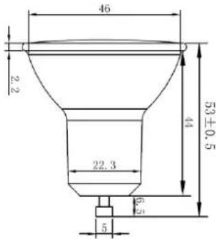
text_image
46 2.2 53±0.5 44 22.3 5 5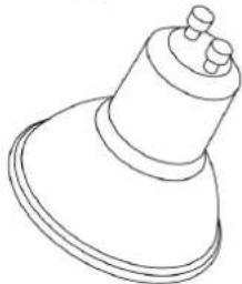
natural_image
Line drawing of a mechanical component with a conical top and flange (no text or symbols)TROUBLESHOOTING
| Fault | Possible Cause | Solution |
| Light on, but motor does not work | Fan switch turned off | Select a fan switch position. |
| Fan switch failed Contact Everdure Service. | ||
| Motor failed Contact Everdure Service. | ||
| Light does not work, motor does not work | House fuses blown Reset/Replace fuses. | |
| Power cord loose or disconnected | Refit cord to power outlet.Switch power outlet on. | |
| Oil leakage | One-way valve and the air ventilation entrance are not tightly sealed | Take down the one-way valve and seal with sealant. |
| Leakage from the connection of U-shaped section and cover | Take U-shaped section down and seal. | |
| Lights not working | Broken/Faulty LED lamp | Contact Everdure Service. |
| Insufficient suction | The distance between the rangehood and the gas top is too far | Refit the rangehood to the correct distance. |
| The Rangehood inclines | The fixing screw not tight enough | Tighten the hanging screw and make it horizontal. |
A division of Shriro Australia Pty Ltd 104 Vanessa Street, Kingsgrove NSW 2208
AUSTRALIA: 1300 355 541
www.everdure.com
NEW ZEALAND: (09) 415 6000
www.everdure.co.nz
IM Ref: RBES632(B)-RBES912 v6 06/02/2020
FOR INDOOR USE ONLY