RISE 2000 - Flat screen mount VOGELS - Free user manual and instructions
Find the device manual for free RISE 2000 VOGELS in PDF.

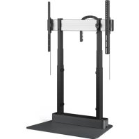
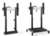
| Product Type | Height-adjustable flat screen support with motorized lifting system |
| Brand | VOGELS |
| Model | RISE 2000 |
| Intended Use | Indoor, dry rooms, wall or cart mounting |
| Installation | By a certified installer |
| Power Supply | Grounded electrical outlet |
| Main Functions | Motorized height adjustment, collision detection |
| Mechanical Safety | Anti-collision system for mechanism protection, do not use as human protection |
| Electrical Safety | Do not open, risk of electric shock. Disconnect before moving |
| Maintenance and Cleaning | Clean with a dry cloth only, no liquids |
| Spare Parts and Repairability | Use only provided original parts. No user-serviceable parts inside |
| Mounting Accessories | Not included, choose according to wall/ceiling material |
| Wheels (if equipped) | Use on flat floors, front brakes locked during use, move in low position |
| Safety Distance | At least 20 cm around the device during movement |
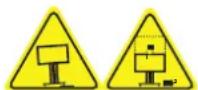
| Important Instructions | Read the entire manual before installation. Risk of crushing |
Frequently Asked Questions - RISE 2000 VOGELS
User questions about RISE 2000 VOGELS
0 question about this device. Answer the ones you know or ask your own.
Ask a new question about this device
Download the instructions for your Flat screen mount in PDF format for free! Find your manual RISE 2000 - VOGELS and take your electronic device back in hand. On this page are published all the documents necessary for the use of your device. RISE 2000 by VOGELS.
USER MANUAL RISE 2000 VOGELS
natural_image
Mechanical support frame with black frame and white central component against red background (no text or symbols)Installation & User Manual
EN Product manual
DE Produkthandbuch
Declaration of Conformity 10
Mounting Instructions 11
User Instructions 24
Product Data Sheet 26
Checklist 27
Contact Details 30

Important safety information for both installer and user
Installer: Before starting the installation read the safety instructions, the mounting regulations and rest of this product manual carefully. Failure to read, thoroughly understand, and follow all instructions can result in serious personal injury, damage to equipment, or voiding of factory warranty! It is the certified installer's responsibility to make sure all mounting systems/accessories are properly assembled and installed using the instructions provided. User: Please carefully read the below safety information and user manual (if included) before using the height adjustable mount or trolley. This ensures a proper working unit and avoids accidents.

Electrical Safety
Connect unit to a properly grounded outlet only. Make sure, the unit can be immediately separated from the power outlet. Only use unit in dry rooms, protect it from water and other liquids. Only wipe unit with dry cloth. Do not open lift unit. RISK OF ELECTRIC SHOCK. There are no serviceable parts inside. In case of dysfunction unplug unit from power outlet and call an authorised technical service person. Do not overrun line cord or damage it in any other way. Replace damaged line cords immediately with new identical ones.

Mechanical safety
Assure installation of unit by authorized service person only. Only use original mounting parts provided with the system and do not use attachments not recommended by the manufacturer. Do not improperly load unit: For the max. load of unit please refer to the page with the specification sheet in this manual. Do not exceed: Use with heavier screens may result in instability causing tipping over resulting in death or serious injury! The height adjustable feature of this unit will not function properly if the weight exceeds the given maximum load. Use this mounting system only for its intended use as described in these instructions. Do not hang on unit. VERY HEAVY UNIT. Severe risk of injury when unit tips over due to improper usage.
The socket connections of the unit and the wall socket must be easily accessible. Disconnect mains plug before moving the product.

The unit is not dripping or splash water protected. Do not place objects filled with liquids on or spray the unit. To reduce the risk of electric shock: Always unplug the unit from the electrical outlet before cleaning.

Always keep product's motion path free from obstacles. Before moving the unit up or down assure at least a safety distance of 20 cm/7.9 inch from any part of the unit to any other fitment in order to avoid shear traps or squeezing points. In case of accident please release operating panel. Movement of unit will stop immediately.
Anti-Collision - Function and intended use
Collision detection is a system to detect contact between the display lift system and an object, in order to mitigate the effects of the impact. This collision detection system is intended for protection of the display lift hardware, however is explicitly not intended as a safety mechanism to prevent personal injury.
Does your unit have wheels?
Only operate unit on plane and stable floors. Move unit on plane floors only. Risk of tilting when overrunning floorunevennesses, door sills and similar. VERY HEAVY UNIT. Severe risk of injury when unit tips over.
Lock brakes of front wheels when operation unit. Always move your trolley with the screen in the lowest position.

Mounting regulations WARNING
A correct mounting is extremely important and this is not the responsibility of Vogel's Products. Faulty mounting may result in injury to persons or damage to equipment. Vogel's Products will not be responsible in any way if the product has been mounted incorrectly. Mounting fittings are not included with the product for reasons of safety, since the properties and bearing strength of walls/ceilings are specific for each case. Suitable mounting fittings must be selected based on the material of the wall/ceiling.
Obtain advice from a specialist in the field or from a specialist shop concerning the choice of mounting fittings. It is the responsibility of the installer to ensure that the wall/ceiling can support at least four times the combined weight of the screen/projector and bracket. The maximum load for this product is given in these mounting instructions. The instructions for installation and use of the screen/projector must also be followed with respect to the location and attachment of the screen/projector.
In case of technical issues please contact your installer

ADDITIONAL SAFETY INFORMATION
1. Power rating: Technical guideline
The lifting system is equipped with an Y-cable. The first lead of the Y-cable is used for the internal power supply of the lift system (400W). The installer has the possibility to connect a display and other peripherals of max 900W to the other lead of the Y-cable. The total system (lift system + peripherals) can therefore draw a maximum of 900W + 400W = 1300W.
2. Stability of equipment
Never place the equipment in an unstable location. A display set may fall, causing serious personal injury or death.
Many injuries, particularly to children, can be avoided by taking simple precautions such as:
- Using stands/frame recommended by the manufacturer of the motorized display lift/monitor.
- Ensuring the display is not overhanging the edge of the supporting frame.
- Educating children about the dangers of climbing on furniture to reach the display or its controls. If the existing set is going to be retained and relocated, the same considerations as above should be applied.
To prevent injury, the equipment set must be securely attached to the floor/wall and the trolley must be in a stable location in accordance with the installation instructions.
3. Caution:
This stand or carrier is intended for use only with a display/monitor of max. 98 inch (max. 100KG), designated accessories and/or designated whiteboard sets Vogel's RISE WBSxx(M). Use with other equipment may result in instability causing injury.
4. Caution while moving the lift
In case only one column moves during operating or reset, stop immediately and contact Vogel's.
EU DECLARATION OF CONFORMITY
Declaration number:
DOCIP 3425103
Name and address of manufacturer / EU-AR:
Vogel's Hondsruglaan 93 5628 DB Eindhoven Netherlands
THIS DECLARATION OF CONFORMITY IS ISSUED UNDER THE SOLE RESPONSIBILITY OF:
Name and address of manufacturer:
Vogel's Hondsruglaan 93 5628 DB Eindhoven Netherlands
Product identification:
RISE 2000-5200 Direct control 73xxxxx See appendix A for a list of all products covered by this declaration
The object of the declaration described above is in conformity with the relevant Union harmonisation legislation:
Electromagnetic Compatibility (EMC) Directive 2014/30/EU Machinery Regulation (EU) 2023/1230 Restriction of Hazardous Substances (RoHS) Directive 2011/65/EU
Harmonised standards:
Safety of machinery EN ISO 12100:2010
Safety of electrical equipment EN IEC 60335-1:2023 + A11:2023
Exposure of humans to electromagnetic fields (EMF) EN 12198-1:2000+A1:2008
Electromagnetic Compatibility (EMC)
EN IEC 55014-1:2021 EN IEC 55014-2:2021 EN IEC 61000-3-2:2019 + A1:2021 + A2:2024 EN 61000-3-3:2013 + A1:2019 + A2:2021 + A2:2021/AC:2022-01
SIGNED FOR AND ON BEHALF OF:
Place and date of issue:
Eindhoven, 29 July 2025
Signature:
Name, position:
Gerard Kanters Quality Manager
Company name:
Vogel's
APPENDIX A - list of products
The following products are covered by EU declaration of conformity DOCIP 3425103:
7320000
RISE 2000 MOTORIZED WALL DC B EU
7320001
RISE 2000 MOTORIZED WALL DC W EU
7352000
RISE 5200 MOTORIZED TROLLEY DC B EU
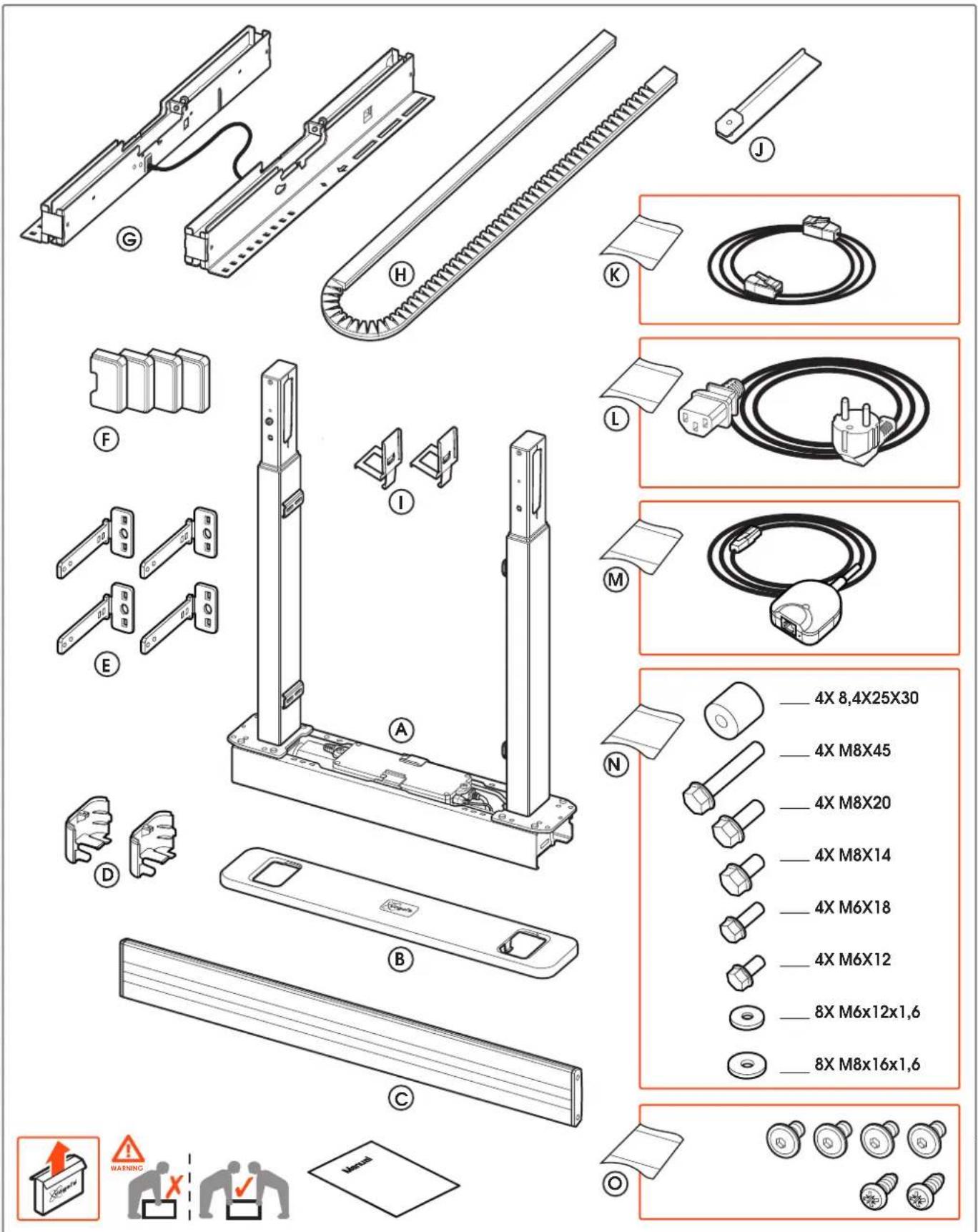
text_image
Exploded view diagram of a battery pack assembly with labeled parts and specifications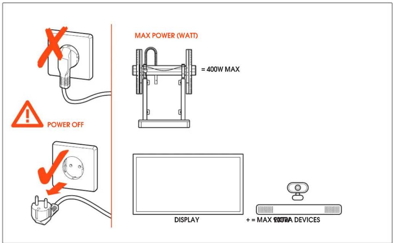
text_image
MAX POWER (WATT) = 400W MAX POWER OFF DISPLAY + = MAX POURA DEVICES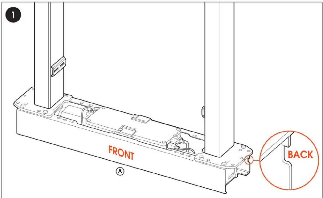
text_image
FRONT BACKwww.vogels.com
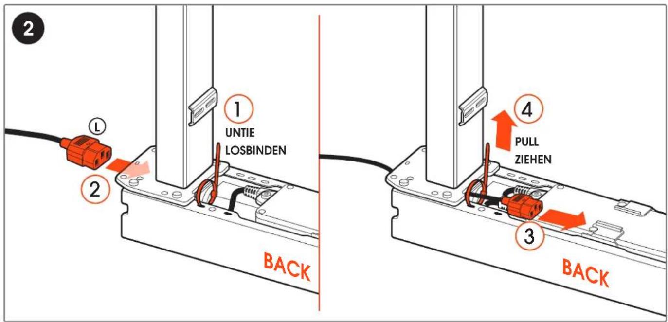
text_image
2 ① UNTIE LOSBINDEN ② BACK ④ PULL ZIEHEN ③ BACK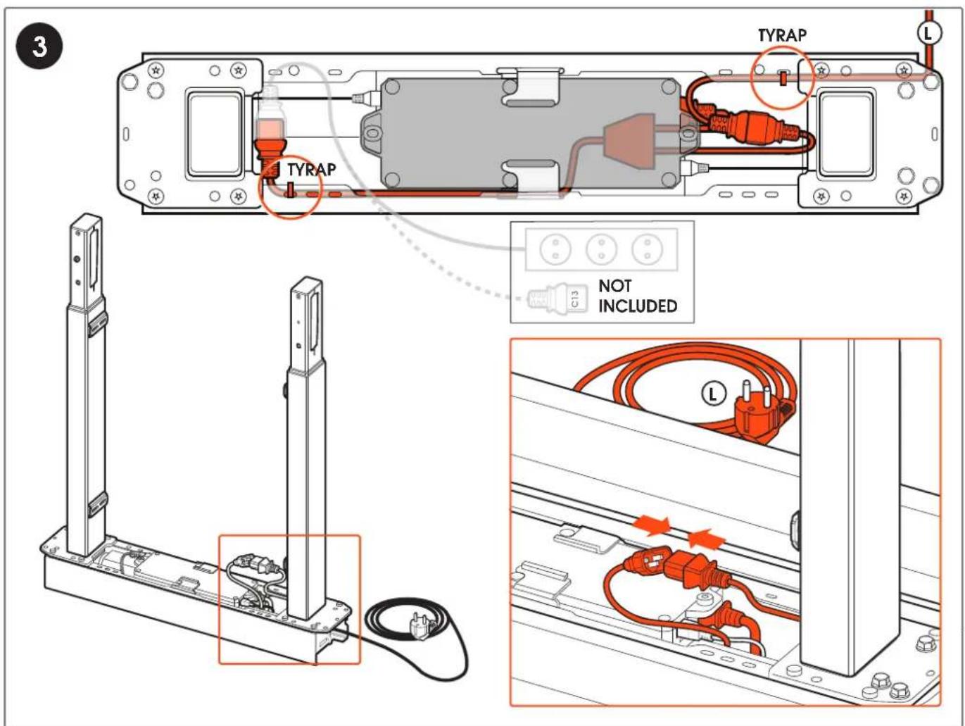
text_image
3 TYRAP L TYRAP NOT INCLUDED C13 Lwww.vogels.com
text_image
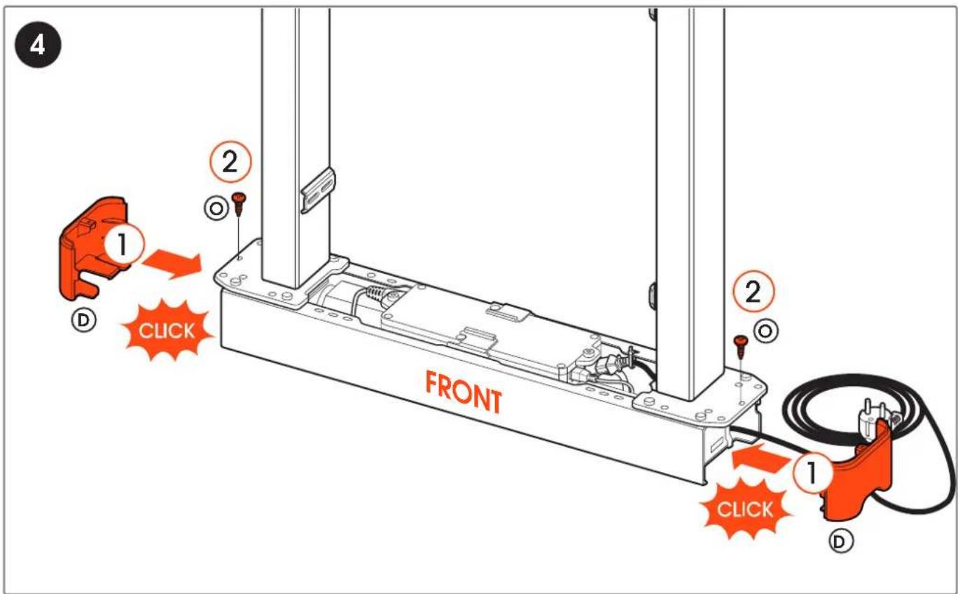
4 1 2 D CLICK FRONT 2 O 1 CLICK D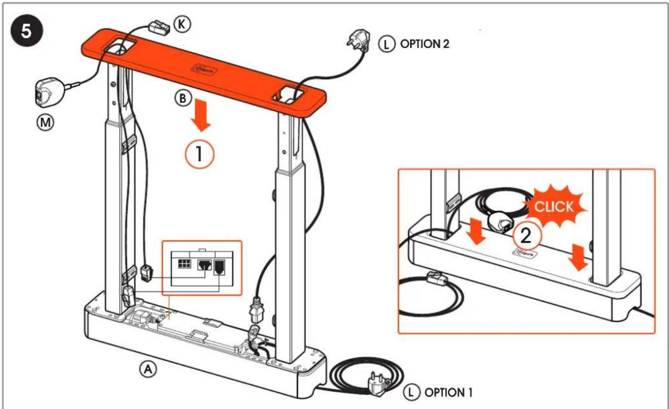
text_image
5 K M ① ② ① OPTION 2 A ① OPTION 1 L OPTION 1 B C L OPTION 2 CLICKwww.vogels.com
text_image
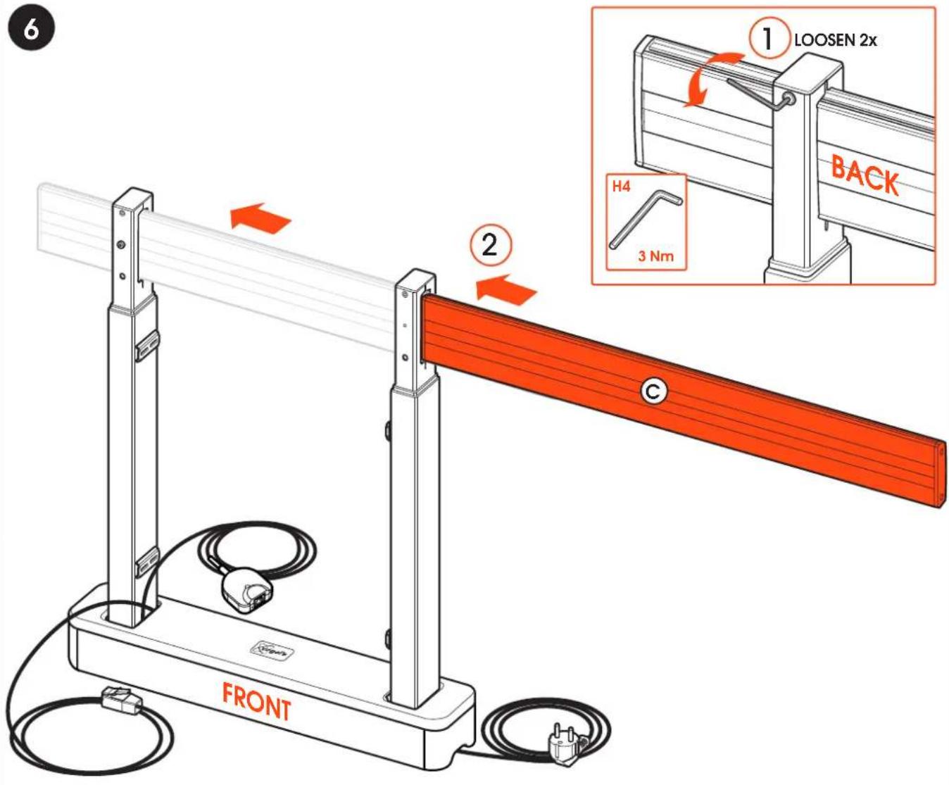
6 ① LOOSEN 2x BACK H4 3 Nm ② FRONT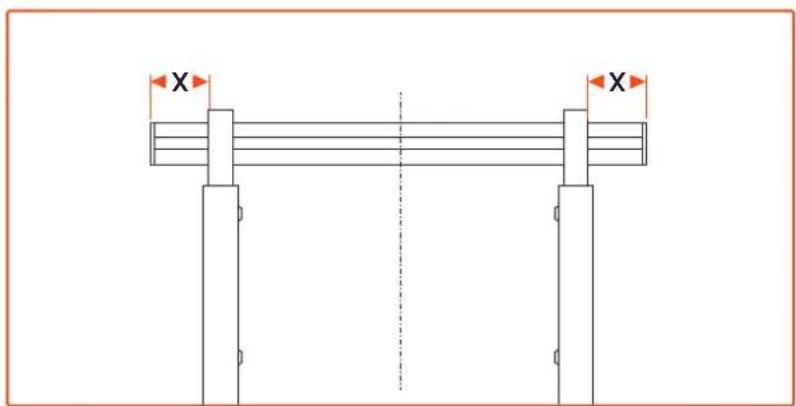
text_image
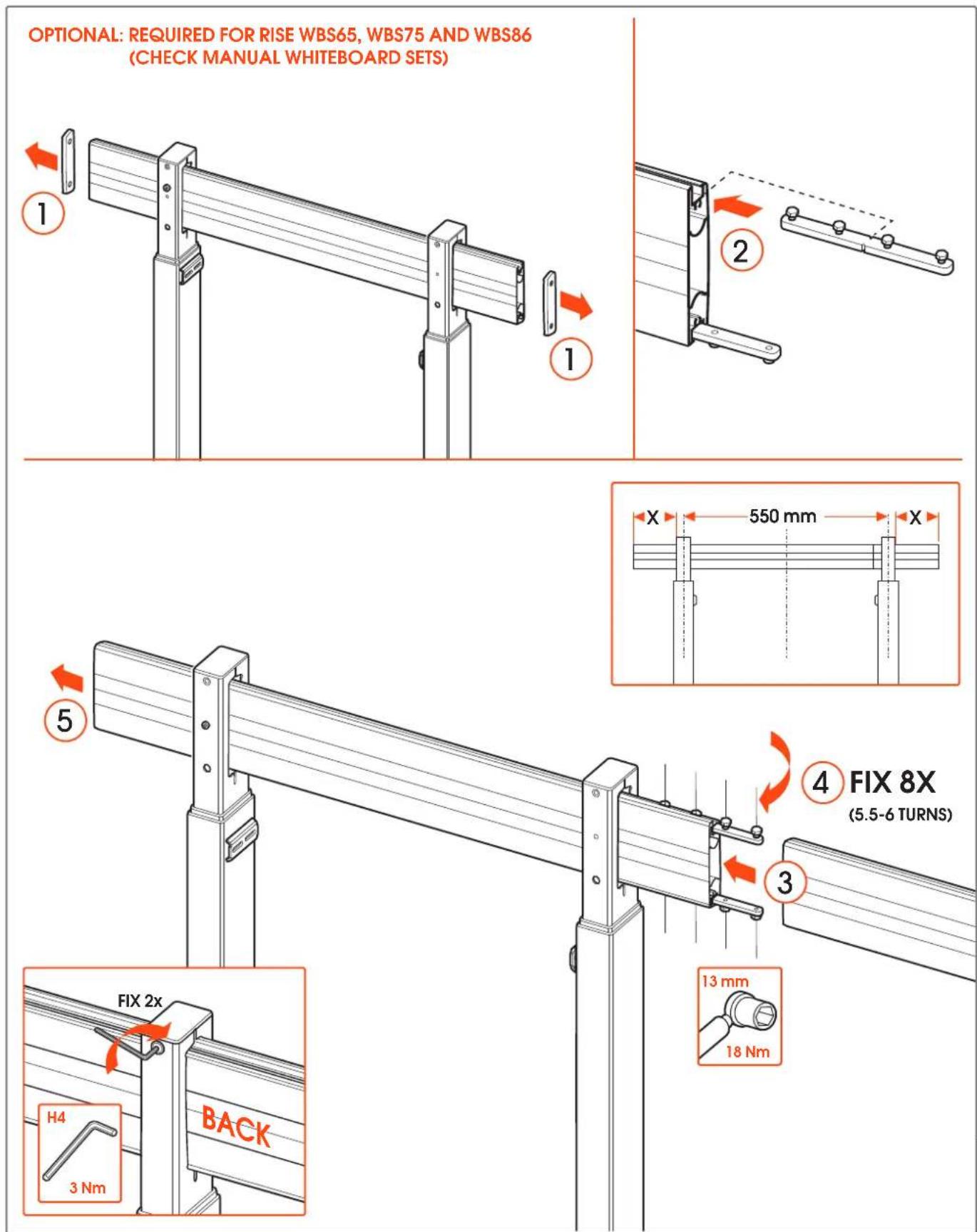
X X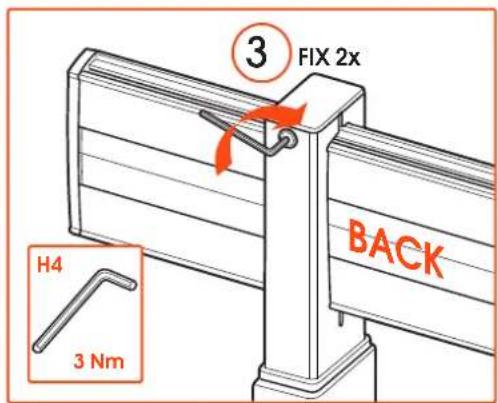
text_image
3 FIX 2x H4 3 Nm BACKwww.vogels.com
www.vogels.com
text_image
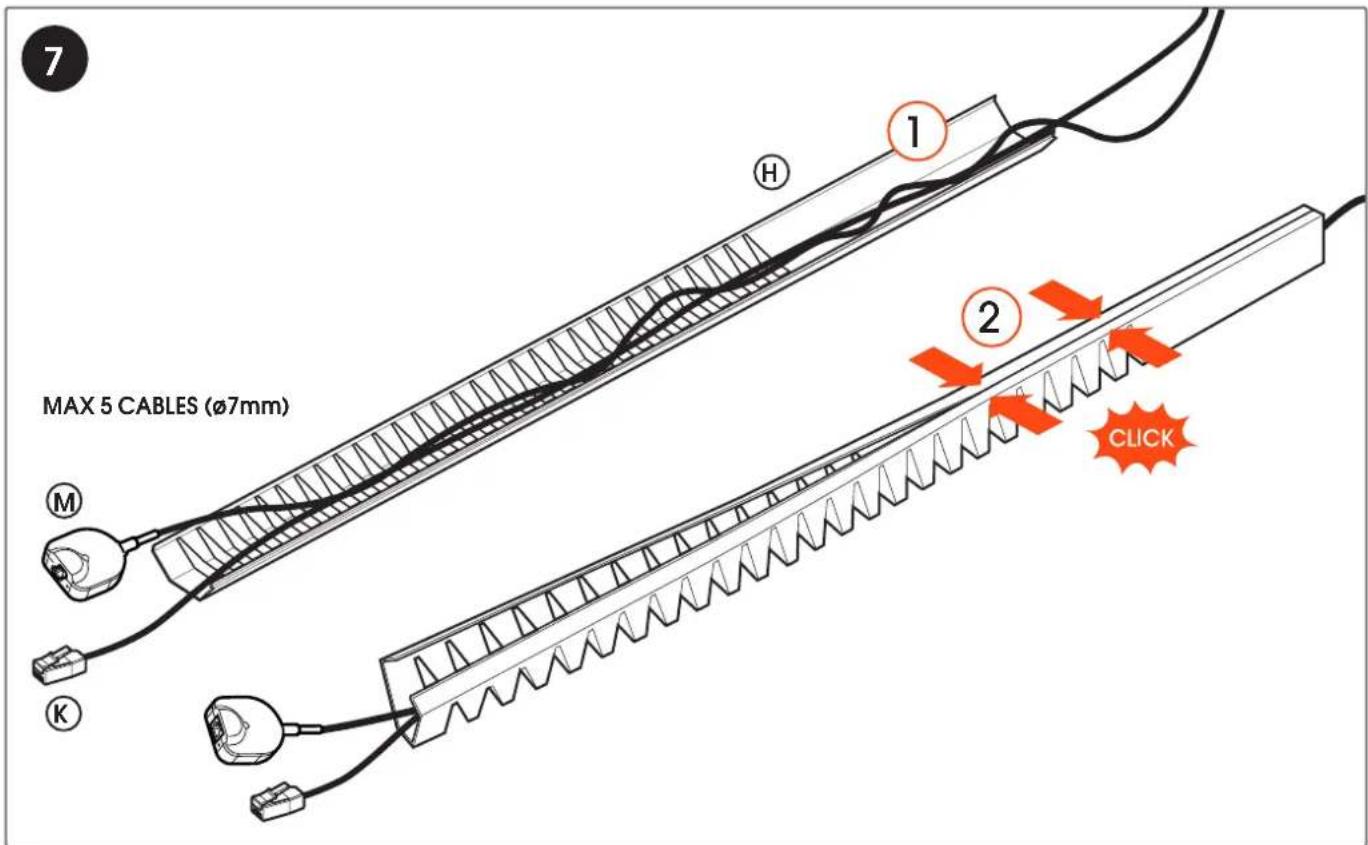
MAX 5 CABLES (Ø7mm) ① ② CLICK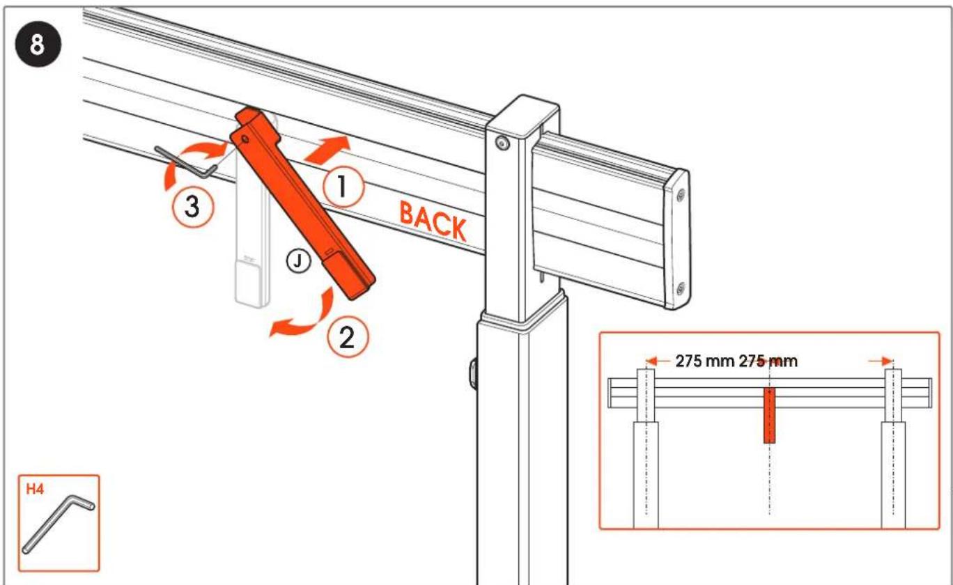
text_image
8 1 BACK 3 J 2 H4 275 mm 275 mmwww.vogels.com
text_image
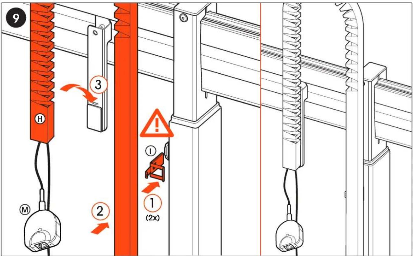
9 H 3 ① ② (2x) ③ ④ ⑤ M10
text_image
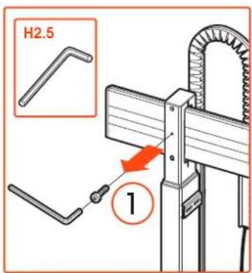
H2.5 1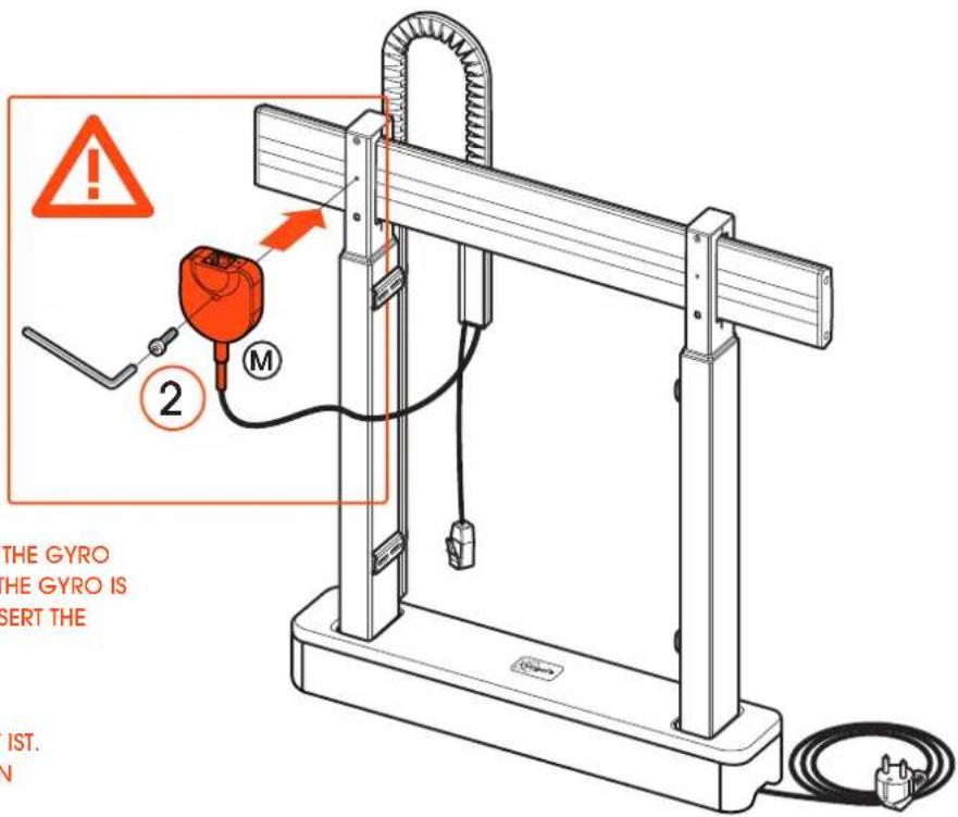
text_image
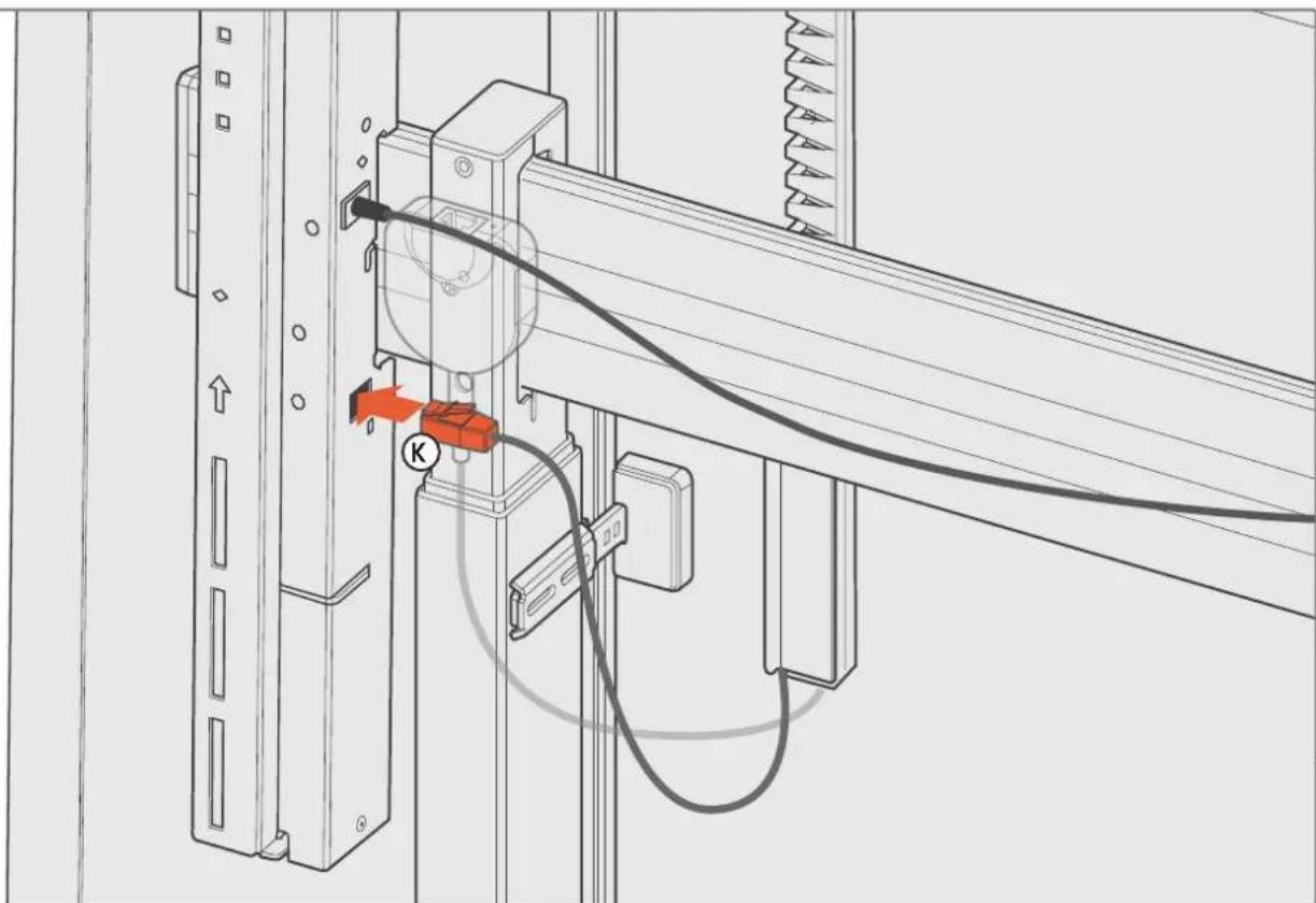
THE GYRO THE GYRO IS INSERT THE IST. NWARNING: THE LIFT DOES NOT FUNCTION IF THE GYRO IS NOT MOUNTED CORRECTLY. MAKE SURE THE GYRO IS MOUNTED FIRMLY TO THE COLUMN AND INSERT THE CONNECTOR INTO THE CONTROL BOX.
ACHTUNG: DER LIFT FUNKTIONIERT NICHT, WENN DER GYRO NICHT RICHTIG MONTIERT IST. STELLEN SIE SICHER, DASS DER GYRO FEST AN DER SÄULE MONTIERT IST UND STECKEN SIE DEN STECKER IN DIE STEUERBOX.
text_image
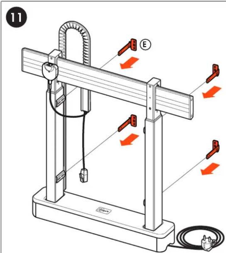
11 E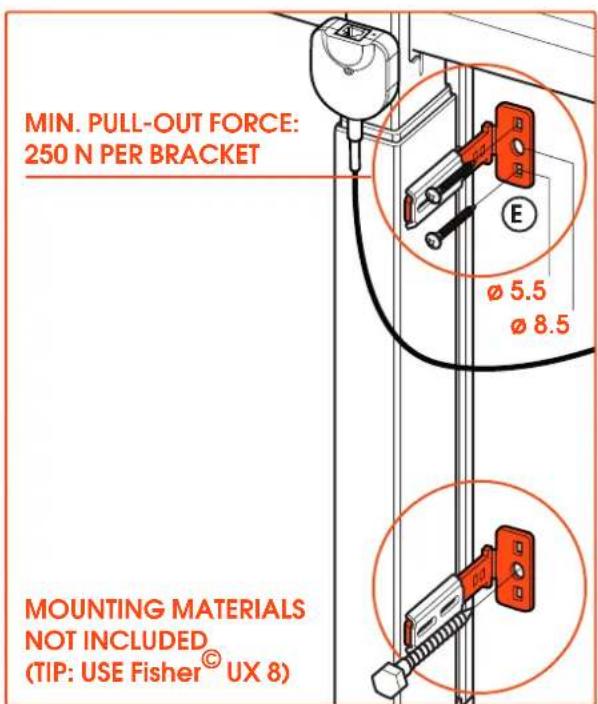
text_image
MIN. PULL-OUT FORCE: 250 N PER BRACKET MOUNTING MATERIALS NOT INCLUDED (TIP: USE Fisher® UX 8)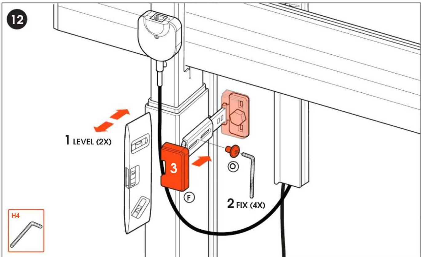
text_image
12 1 LEVEL (2X) 3 F 2 FIX (4X) H4www.vogels.com
OPTIONAL: REQUIRED FOR RISE WBS65, WBS75 AND WBS86 (CHECK MANUAL WHITEBOARD SETS)
natural_image
Technical diagram of a mechanical testing setup with labeled components and directional arrows (no text or symbols present)13
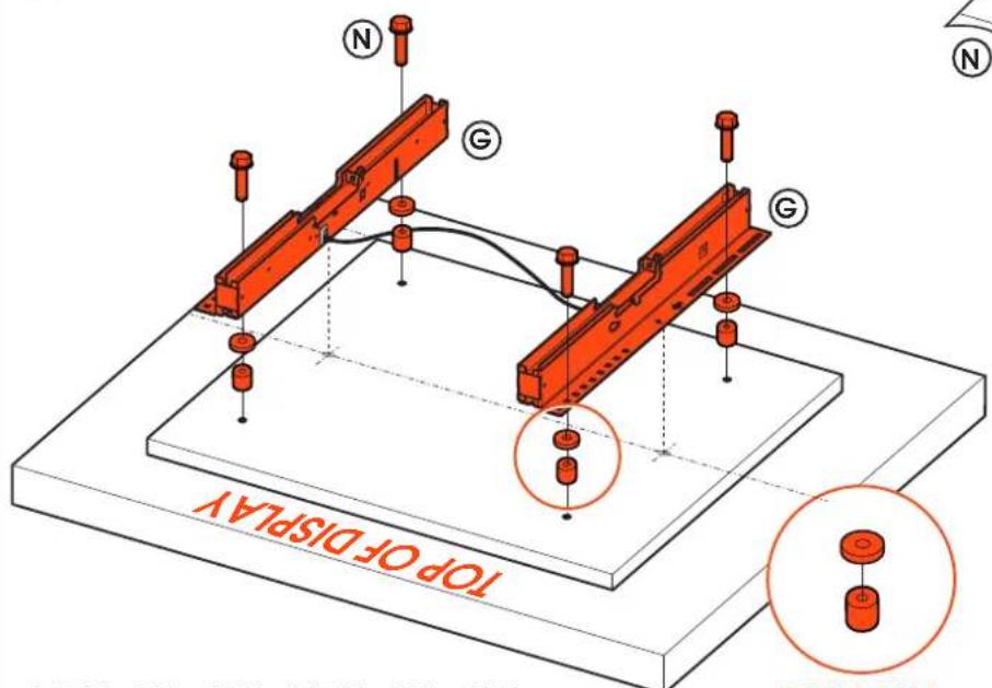
text_image
TOP OF DISPLAY N G G NVESA 300x300 - VESA 800x600

4X 8,4X25X30
4X M8X45

4X M8X20

4X M6X18

4X M6X12

8X M6x12x1,6

8X M8x16x1,6
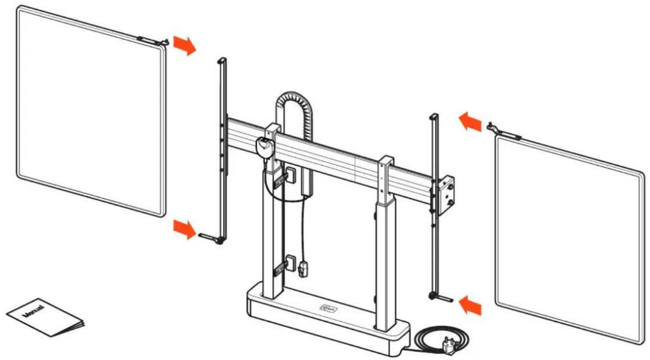
14
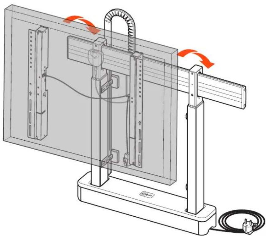
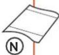
natural_image
Technical diagram of a mechanical assembly with red arrows indicating motion or force direction (no text or symbols present)15
natural_image
Technical line drawing of a mechanical assembly with no visible text or symbolswww.vogels.com
text_image
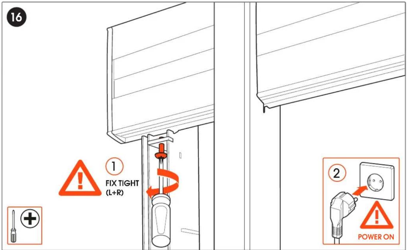
16 1 FIX TIGHT (L+R) 2 POWER ON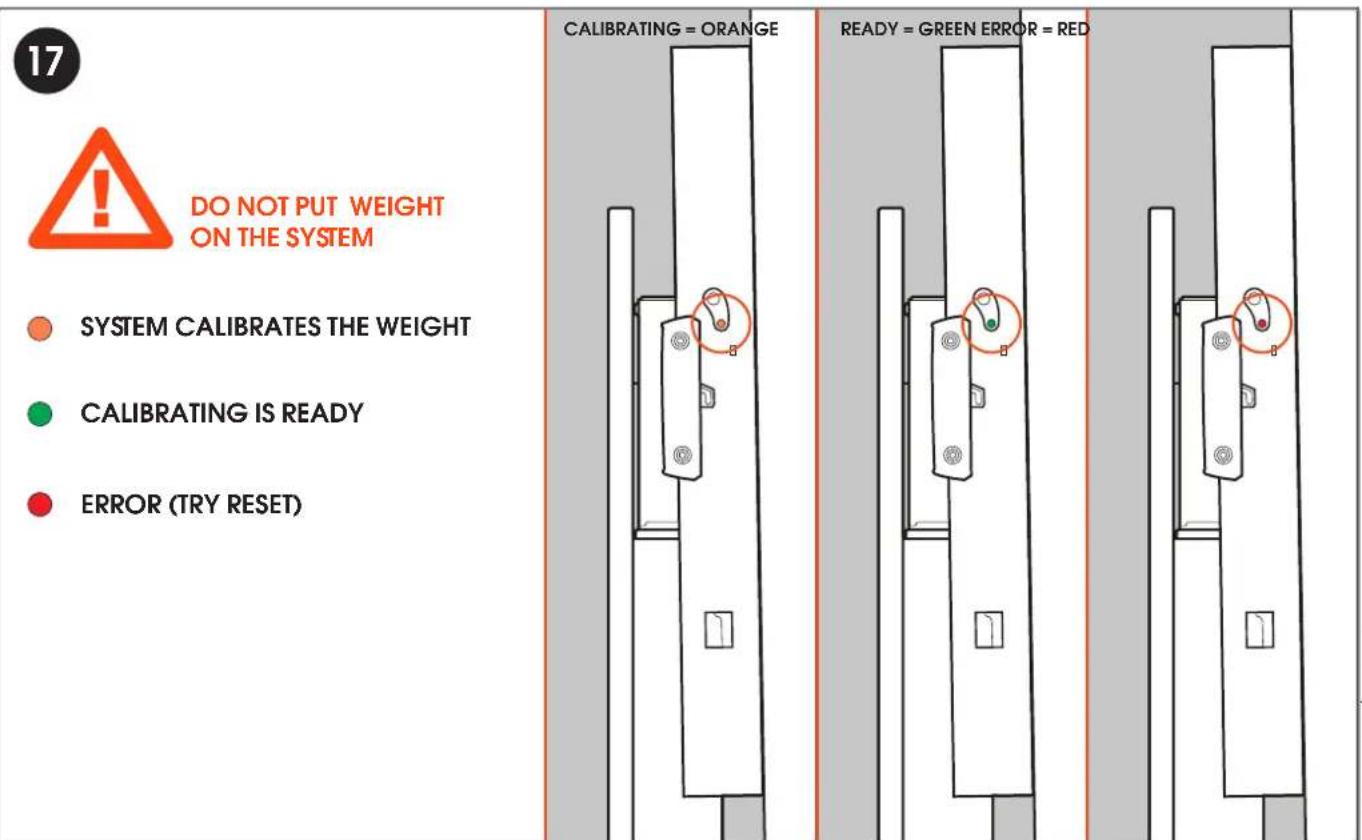
text_image
DO NOT PUT WEIGHT ON THE SYSTEM SYSTEM CALIBRATES THE WEIGHT CALIBRATING IS READY ERROR (TRY RESET) CALIBRATING = ORANGE READY = GREEN ERROR = REDwww.vogels.com
18
OPERATION BY MANUALLY
APPLYING PRESSURE
natural_image
Simple line drawing of a wall socket connected to a cable (no text or symbols)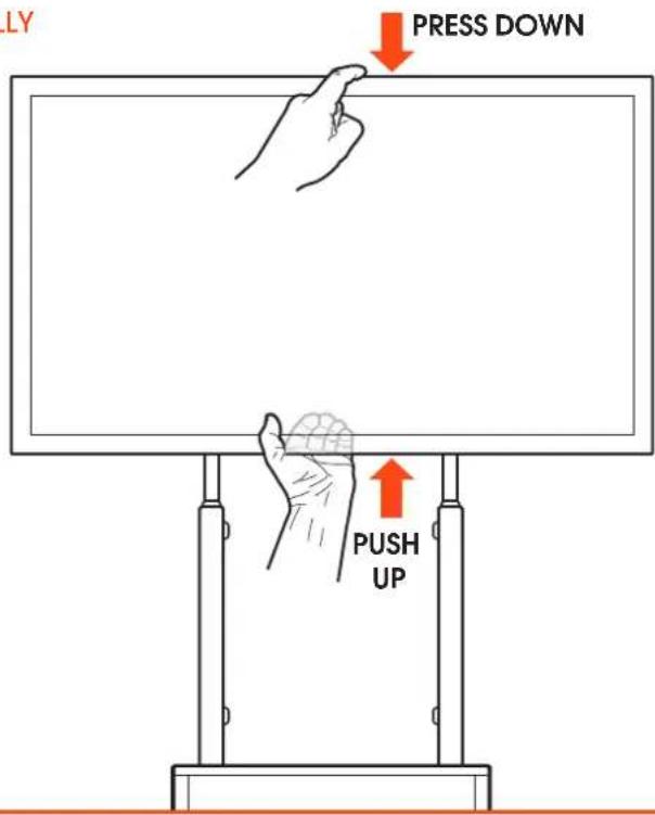
text_image
LY PRESS DOWN PUSH UP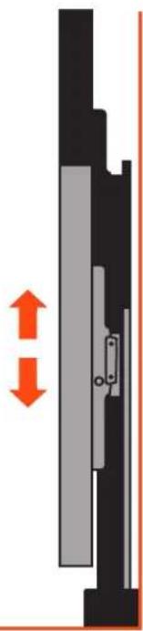
natural_image
Pure mechanical assembly diagram showing a vertical component with internal components and an orange double-headed arrow indicating motion (no text or symbols)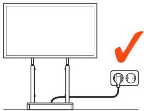
text_image
Diagram showing a monitor connected to an electrical outlet with a red checkmark indicating approval or verification.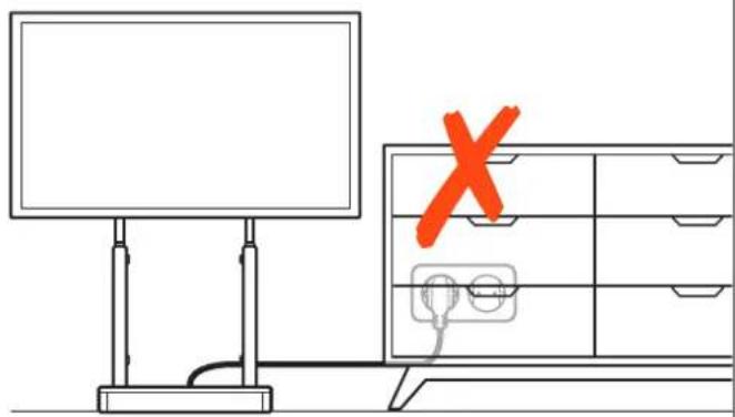
text_image
Diagram showing a monitor and a cabinet with an orange 'X' mark, indicating a warning or error.MAXIMUM LOAD OF THE LIFT IS 140 KG / 308 LBS. MAXIMUM WEIGHT OF THE DISPLAY IS 100 KG / 220 LBS.
MAXIMALE BELASTUNG FÜR DIESEN LIFT IST 140 KG / 308 LBS. MAXIMALE GEWICHT DES BILDSCHIRMS IST 100 KG / 220 LBS.
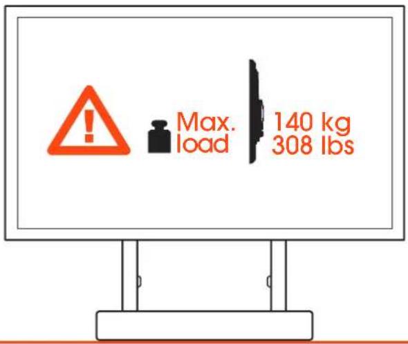
text_image
Max. load 140 kg 308 lbs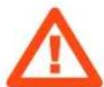
GB Caution! Risk of crushing
natural_image
Simple line drawing of a blank rectangular monitor with a base stand (no text or symbols)
natural_image
Silhouette of a woman holding a child's hand, both pointing together (no text or symbols)OPERATING FUNCTIONALITY RISE
| FUNCTION REQUIRED ACTION | |
| Going up PUSH DISPLAY UP | |
| Going down PULL DISPLAY DOWN | |
| Reset system 1. Move system to lowest position (if possible). If not, start with point 2.2. Pull display down and hold at least 10 seconds, indicator LED will become red.3. Release display and pull again until system gives visual feedback reset is finished.4. In case of a set bottom limit, lift will go ‘up’ after finishing reset up to the set limit.5. Indicator LED will become green. | |
| Hard System Reset 1. Unplug power cable, and all motor cables for 30 seconds. Then connect aII cables again.2. Move system to lowest position (if possible). If not, start with point 2 (Reset system).3. Pull display and hold at least 10 seconds, indicator LED starts to blink orange.4. Release display and pull again until system gives visual feedback reset is finished.5. In case of a set bottom limit, lift will go ‘up’ after finishing reset up to the set limit.6. Indicator LED will become green. | |
 CAUTION DURING RESET:IF ONLY ONE COLUMN MOVES DURING RESET, STOP IMMEDIATELY AND CONTACT VOGEL'S CAUTION DURING RESET:IF ONLY ONE COLUMN MOVES DURING RESET, STOP IMMEDIATELY AND CONTACT VOGEL'S | |
CAUTION DURING RESET:
IF ONLY ONE COLUMN MOVES DURING RESET, STOP IMMEDIATELY AND CONTACT VOGEL'S
TROUBLE SHOOTING GUIDE:
- Check whether all cables are still connected (power cable, DirectControl cable, gyroscope and motor cables)
- Check which color the indicator light blinks:
a. Green: Active
b. Orange blinking: Calibrating
c. Red: Reset/error
- If there is no object obstructing the lift (anymore), run a system reset.
- If a System Reset, doesn't solve it, try to run a hard reset.
- Contact Vogel's
natural_image
Technical line drawing of a mechanical clamp or bracket assembly (no text or symbols)CE
Power supply:
100-240V \~ 50/60Hz
Rated current:
EU/UK: 6A, US/CA: 15A
Power consumption lift system:
400W
Max power external devices:
900W
Product data sheet
PRODUCT DATA SHEET RISE 2000
Dimensions in mm [inch]
Screen sizes:
55inch - 98inch
Max. display weight:
100kg / 220,5 lbs
Max. load wall lift:
140kg/308,6lbs
Net weight:
32,7 kg / 72 lbs
Gross weight:
34 kg / 74,9 lbs

text_image
915[36,0] MAX 800 [31.5] MIN 300 [11.8] MIN 300 [11.8] MAX 600 [23.6] MIN 806 [31.7] MAX 1786 [70.3] 733[28,9] 100[3,9]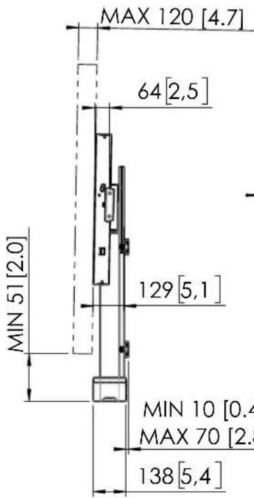
text_image
MAX 120 [4.7] 64 [2,5] MIN 51 [2.0] 129 [5,1] MIN 10 [0.4] MAX 70 [2.8] 138 [5,4]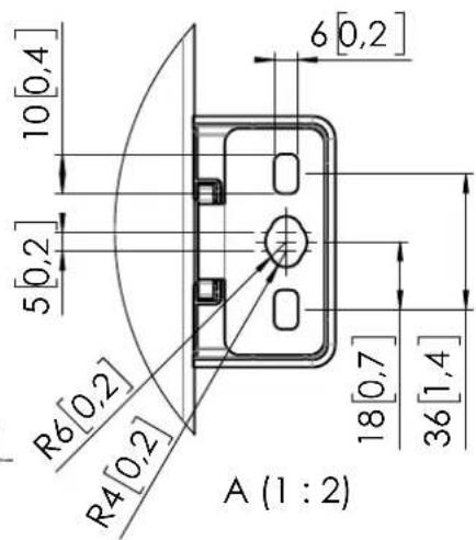
text_image
10[0,4] 5[0,2] R6[0,2] R4[0,2] 6[0,2] 18[0,7] 36[1,4] A (1 : 2)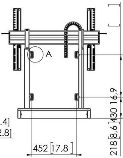
text_image
.4] .8] A 452 [17,8] 218 [8,6] 430 16,9Note: This document and specifications herein are confidential and the exclusive property of Vogel's Products b.v. Neither this design nor any information contained in this drawing may be reproduced or disclosed to others without written consent of Vogel's Products e.v. The design and information will not be reproduced, copied or used, etc. in part of this document. The basis for the manufacture or sale of items without written permission.
Warning: Please study all instructions and illustrations carefully before installation.
Information in this document is subject to change without further reliance.
T510279 01
Product data sheet
27-11-24

CHECKLIST
RISE 2000 DIRECT CONROL MOTORIZED DISPLAY LIFT FLOOR-WALL SOLUTION:
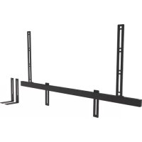
☐ Check whether the interface strips have been secured to the interface bar by fixing the screws from the bottom.
☐ Check whether maximum weight of the display (max. 100kg) and lift + peripherals (max. 140 kg) is not exceeded.
☐ Check whether maximum total weight of lift is 140kg.
☐ Check whether maximum power of the display + peripherals does not exceed 900W.
☐ Check whether the power cord has strain relief.
☐ Check that all cables are neatly secured, concealed and do not come into contact with sharp edges.
☐ Check if the gyroscope is mounted correctly.
☐ Check whether the plug is easily accessible.
☐ Check that there are no obstacles in the movement area of the product (bottom + top).
☐ Check whether there is at least a distance of 51mm between floor and display in the lowest position.
□ Check whether the lift can make it's full stroke by operating the system up an down completely, and make sure no cables get stuck.
NAME :
DATE :
SIGNATURE :
Vogel's Products BV
HONDSRUGLAAN 93,
5628 DB EINDHOVEN,
THE NETHERLANDS
T +31 (0)40 264 74 00
E info@vogels.com
W www.vogels.com
(GB) Subject to printing errors and technical amendments.
(NL) Drukfouten en technische wijzigingen voorbehouden.
(F) Sous réserve de fautes d'impression et de modifications techniques.
(D) Für Druckfehler übernehmen wir keine Verantwortung. Technische Änderungen vorbehalten.
(E) Reservados errores de imprenta y sujete a modificaciones.
(1) Con riserva di modifiche techniche e di eventueli errori di stampa.
(P) Reserva-se a ocorrência de gralhas e de modificações técnicas.
(H) Nyomdahibák és technikai változtatások joga fenntartva.
(PL) Zastrzega się możliwość występowania błędów drukarskich i zmian technicznych.
(RUS) Возможны ошибки при печати и технические модификации.