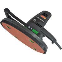
EWS 400 - Sander Eibenstock - Free user manual and instructions
Find the device manual for free EWS 400 Eibenstock in PDF.




| Product type | Slow sander for plasterboard and EPS polystyrene (ITE) |
| Brand | Eibenstock |
| Model | EWS 400 |
| Rated voltage | 230 V ~ |
| Frequency | 50 / 60 Hz |
| Power consumption | 800 W |
| No-load speed | 140 min⁻¹ |
| Speed under load | 0 - 85 min⁻¹ (variable) |
| Disc diameter | 370 mm |
| Weight | 3.9 kg |
| Protection class | II (double insulation) |
| Protection degree | IP 20 |
| Interference suppression | EN 55014 and EN 61000 |
| Delivery contents | Sander with Velcro plate, pin spanner, extraction hood, base, instruction manual |
| Recommended special accessory | Velcro abrasive disc P24 (set of 3, ref. 37671000), Industrial vacuum cleaner DSS 25 M (ref. 09917000) |
| Application | Professional, sanding of polystyrene and mineral insulating boards |
| Speed variator | Electronic, by pressure on the trigger |
| Dust extraction | Mandatory with industrial vacuum cleaner DSS 25 M |
| Sound pressure level | 77 dB(A) (LpA) |
| Sound power level | 88 dB(A) (LwA) |
| Vibration emission value | 1.0 m/s² |
| Warranty | 12 months for companies (proof required) |
Frequently Asked Questions - EWS 400 Eibenstock
User questions about EWS 400 Eibenstock
0 question about this device. Answer the ones you know or ask your own.
Ask a new question about this device
Download the instructions for your Sander in PDF format for free! Find your manual EWS 400 - Eibenstock and take your electronic device back in hand. On this page are published all the documents necessary for the use of your device. EWS 400 by Eibenstock.
USER MANUAL EWS 400 Eibenstock
Original Instructions....11 - 18
Notice originale....19 - 26
natural_image
Exterior view of a black EIBENSTOCK electric power tool with green handle and red textured base (no text or symbols on body)Wichtige Hinweise
natural_image
Four circular icons showing different human and safety symbols: headphones, glasses, hand gesture, and gloves (no text or labels)Gehörschutz tragen
Schutzbrille tragen
natural_image
Close-up of a mechanical device with a labeled component 'A' and an arrow pointing to a circular opening (no readable text or symbols beyond labels)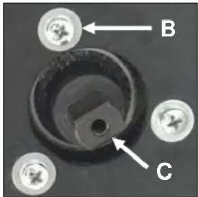
Absaughaube:
natural_image
Close-up of a black mechanical flange with three bolt holes (no text or symbols visible)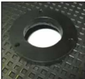
natural_image
Close-up of a black circular mechanical component with a bright center, placed on a textured surface (no text or symbols visible)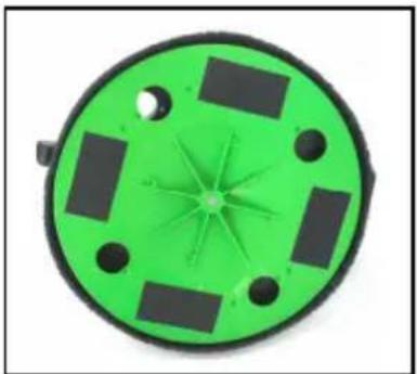
natural_image
Green circular mechanical component with multiple square cutouts and central starburst pattern (no text or symbols)Grundteller:
natural_image
Circular brown object with five white holes, no text or symbols presentnatural_image
Symbol of a trash bin crossed with no text or numbers, representing waste sorting or recycling (no text present)Nur für EU-Länder
Lothar Lässig
General Manager
03.03.2023
Frank Markert
Head of Engineering
Important Instructions
Important instructions and warning notices are allegorated on the machine by means of symbols:



Before you start working, read the operating instructions of the machine.
Work concentrated and carefully. Keep your work-place clean and avoid dangerous situations.
In order to protect the user, take precautions.
During work you should wear goggles, ear protectors, dust mask, protective gloves and sturdy work clothes.




Wear ear protectors
Wear goggles
Wear a dust mask
Wear protective gloves
Technical Data
Insulation board sander EWS 400
| Rated voltage: 230 V ~ | |
| Power input: 800 W | |
| Order number: 0620F000 |
Frequency: 50 / 60 Hz
Rated speed: 0 - 85 rpm
No load speed: 140 rpm
Max. disc diameter: 370 mm
Protection class: II
Degree of protection: IP 20
Weight: about 3,9 kg
Interference suppression: EN 55014 and EN 61000
Available Special Accessories
| Item | Order no. |
| Sandpaper P 24 set of 3 pieces | 37671000 |
| Wet/dry deduster DSS 25 M | 09917000 |
Supply
Insulation board Sander EWS 400 with Velcro-type fastening disc and operating instruction in a cardboard box.
Application for Indented Purpose
The insulation board sander EWS 400 is made for professional use. Together with the appropriate sanding paper insulating boards can be sanded.
Attention!
Only with the original sanding paper and for this purpose optimised Wet/Dry Vacuum Cleaner DSS 25 M an optimal extraction can be assured. In order to protect the user and the machine, the use of the industrial vacuum cleaner is compulsory.
In case of non-observance, you might void your warranty claim.

Safe work with this machine is only possible if you read this operating instruction and follow them strictly.
Additionally, the general safety instructions of the leaflet supplied with the tool must be observed. Prior to the first use, the user should absolve a practical training. Save all warnings and instructions for future reference.

If the connection cable gets damaged or cut during use, do not touch it, but immediately pull the plug out of the socket, Never use the tool with a damaged connection cable.

The tool must neither be wet nor used in humid environment.
- Do not use the tool near explosive materials.
- Do not work with materials containing asbestos.
■ Modifications of the tool are prohibited.
■ Always check the tool, cable and plug before use.
Have damages only repaired by specialists. Only insert the plug into the socket when the tool switch is off. - When the machine runs outside, always use a protection switch (30 mA max.) against fault current.
- Pull the plug out of the socket and make sure is switched off when the machine is not under supervision, e.g. in case of putting up and stripping down, in case of voltage drop or when fixing or mounting an accessory.
- Switch the machine off if it stops for whatever reason. This way you avoid that it starts suddenly and not under supervision.
- Do not use the machine when one part of the housing is damaged or in case of damages on the switch, cable or plug.
- Pay attention that the speed indicated on the tool meets or is higher than the max. speed indicated on the machine.
- Check the accessories before use; do not use damaged products.
■ Before use, make sure that the tool is correctly fixed and fastened. Let it run idle for about 30 seconds in a safe position. If considerable vibrations occur or if other defects are recognised, switch off immediately. - While working, lead the line cord / extension cord and the extraction hose to the back away from the machine.
- Power tools have to be inspected by a specialist in regular intervals.
■ Never carry the machine at its cable. - Do not touch rotating parts.
- Persons under 16 years of age are not allowed to use the machine.
■ While working, wear ear protectors, a dust mask and protective goggles. - Make sure that the persons standing in the work area are not hit by particles which fly around.
- Keep the handles dry, clean and free of oil and grease.
- During operation always hold the machine with both hands.
■ Caution! The tool still runs for a little while after the machine was switched off.
For further safety instructions, please refer to the enclosure!
Assembly
Before initial use, assemble the extraction hood and the base plate.
natural_image
Close-up of a circular mechanical device with a green and black component, labeled 'A' with an arrow pointing to a small hole (no readable text or symbols beyond labels)Extraction hood:
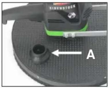
Position the extraction hood so that the suction nozzle (A) is located just to the right of the operating handle (see fig.).
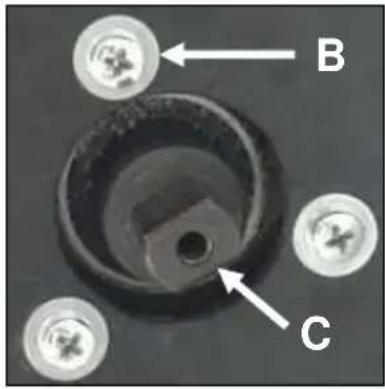
Secure the extraction hood using the three supplied M 5x25 screws and 5.3 mm washers (B) on the mounting on the gear housing.
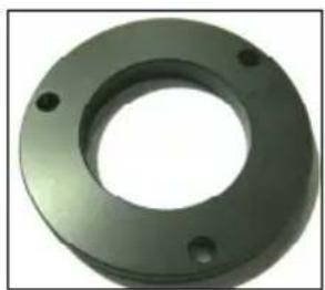
Between gearbox and exhaust hood, the intermediate ring (see picture below) are mounted.
natural_image
Close-up of a black mechanical flange with three bolt holes (no text or symbols visible)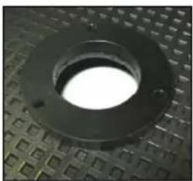
natural_image
Close-up of a circular mechanical component with a bright center, placed on a textured surface (no text or symbols visible)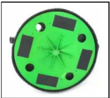
natural_image
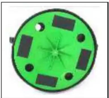
Green circular mechanical component with multiple square cutouts and a star-shaped center (no text or symbols)Base plate:
Push the base plate onto the spindle (C) of the machine and secure using the supplied M6x20 screw.
For assembly, use the supplied screwdriver
Electrical Connection
First, check the correspondence between voltage and frequency against the data mentioned on the identification plate. Voltage differences from + 6% to - 10% are allowed.
The EWS 400 is made in protection class II.
Only use extension cables with a sufficient cross-section. A cross-section which is too small might cause a considerable drop in performance and an overheating of machine and cable.
Recommended minimum cross sections and maximum cable lengths
| Mains voltage | Cross section in sq. mm | |
| 1.5 2.5 | ||
| 110V 20 m 40 | m | |
| 230V 50 m 80 | m | |
Switching on and off
Before connecting the machine to the mains supply, make sure that the machine is switched off.
Short-Time Operation
Switching-on: press on/off switch
Switching-off: release on/off switch
Permanent Operation
Switching-on: press the on/off switch and, keeping it pressed, engage the arrestor button
Switching-off: press the on/off switch and let it go off again
Attention!
In case of every stop of the machine or a power cut, the lock button has to be released immediately by pressing the on/off switch. Consequently, you can avoid an unintentional restart of the machine (physical hazard).
The machine is equipped with an electronic switch. With this switch the speed can be regulated according to the pressure on the button. Only use the electronic switch when you want to start the machine slowly. Permanent use with reduced speed can cause an overload because the motor then gets less cooling air and therefore the machine will be overheated much faster.
Tool Change
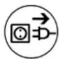
Attention!
Before the beginning of all works disconnect the plug from the mains!
Only use original accessories in order to allow an optimal extraction.

natural_image
Circular brown object with five white holes, resembling a sand or paper (no text or symbols)Press the sanding paper in a way on the sanding plate that the extraction holes are not covered.
The 4 hole punch of both discs makes it possible to centre exactly and to position the sanding paper on the machine easily.
Attention!
Before you start working, check whether the accessory has the exact position.
Let the machine start running in a safe position for a short time. In case the machine does not run easily, immediately stop working.
Dust Extraction
Dust which appears during work is harmful to health. For this reason, use an industrial vacuum cleaner while sanding.
The appropriate Wet/Dry Vacuum Cleaner DSS 25 M is available as accessory. Directly connect it to the nozzles which are meant for it on the dust hood.
Handling
Connect the lead cable of the dry-wall sander with the industrial vacuum cleaner and then connect the extraction hose with dust hood of the sander.
Lead the extraction hose and the cable to the back away from the machine.
Activate the switch-on automatic on the vacuum cleaner.
Switch the machine on and put it carefully on the surface you want to work on. Hold the machine with both hands and move it in a linear or rotary way.
For sanding works directly on wall edges you can remove a segment from the protection hood. This allows working even on spots which are usually hard to reach.

Attention!
Do not touch rotating parts!
Care and Maintenance

Before the beginning of the maintenance or repair works you have to disconnect the plug from the mains.
Repairs may be executed only by appropriately qualified and experienced personnel. After every repair the machine has to be inspected by an electric specialist. Due to its design, the machine needs a minimum of care and maintenance. However, the following points have to be observed:
■ Always keep the power tool and the ventilation slots clean.
- During work, please pay attention that no particles get inside the machine.
- In case of failure, a repair has to be carried out by an authorised service workshop.
Our after-sales service responds to your questions concerning maintenance and repair of your product as well as spare parts.
EIBENSTOCK's application service team will gladly answer questions concerning our products and their accessories.
Environmental Protection

Raw Material Recycling instead of Waste Disposal
In order to avoid damages on transportation, the tool has to be delivered in solid packaging. Packaging as well as unit and accessories are made of recyclable materials and can be disposed accordingly.
The tool's plastics components are marked according to their material, which makes it possible to remove environmental friendly and differentiated because of available collection facilities.
Only for EU countries

natural_image
Symbol of a trash bin crossed with no text or numbers, representing waste sorting or recycling (no text present)Do not dispose of electric tools together with household waste material!
In observance of European Directive 2012/19/EU on waste electrical and electronic equipment and its implementation in accordance with national law, electric tools that have reached the end of their life must be collected separately and returned to an environmentally compatible recycling facility.
Noise Emission
Measured sound values determined according to EN 62841-2-4. Typically the A-weighted noise levels of the product are:
Sound pressure level L_pA 88 dB(A)
Sound power level L_wA 77 dB(A)
Uncertainty K 3 dB

Wear ear protectors!
Vibration total values a_h and uncertainty K determined according to EN 60745:
Vibration emission value a_h 1,0 m/s ^2
Uncertainty K 0,1 m/s ^4
The declared vibration emission level represents the main applications of the tool. However if the tool is used for different applications, with different accessories or poorly maintained, the vibration emission may differ. This may significantly increase the exposure level over the total working period
An estimation of the level of exposure to vibration should also take into account the times when the tool is switched off or when it is running but not actually doing the job. This may significantly reduce the exposure level over the total working period.
Identify additional safety measures to protect the operator from the effects of vibration such as: maintain the tool and the accessories, keep the hands warm, organisation of work patterns.
Warranty
According to the general supply conditions for business dealings, suppliers have to provide to companies a warranty period of 12 months for redhibitory defects. (To be documented by invoice or delivery note.)
Damage due to natural wear, overstressing or improper handling are excluded from this warranty.
Damages due to material defects or production faults shall be eliminated free of charge by either repair or replacement.
Complaints will be accepted only if the tool was returned in non-dismantled condition to the manufacturer or an authorized service centre.
EU Declaration of Conformity
We declare under our sole responsibility that the product described under “Technical Data” is in conformity with the following standards or standardization documents:
DIN EN 62841-1:2016-07 DIN EN 62841-2-4:2015-05+1:2017-07
DIN EN IEC 55014-1:2022-12 DIN EN IEC 55014-2:2022-10
according to the provisions of the directives 2011/65/EU, 2014/30/EU, 2006/42/EG
Technical file (2006/42/EC) at:
Lothar Lässig
General Manager
03.03.2023
Frank Markert
Head of Engineering
Subject to change without notice.
natural_image
Close-up of a black industrial machine component with a green handle and labeled part A (no readable text or symbols beyond label)natural_image
Close-up of a black mechanical flange with three bolt holes (no text or symbols visible)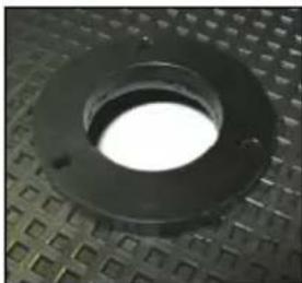
natural_image
Close-up of a black circular mechanical flange with a bright center, placed on a textured surface (no text or symbols visible)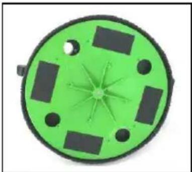
natural_image
Green circular device with black components and a starburst pattern at the center (no text or symbols visible)Socle :
natural_image
Circular brown sand pad with five white holes, no text or symbols presentnatural_image
Symbol of a trash bin with crossed lines indicating no waste or discharge (no text or labels)Lothar Lässig
General Manager
03.03.2023
Frank Markert
Head of Engineering
natural_image
Four circular icons showing different human and facial behaviors: headphones, sunglasses, hand gesture, and gloves (no text or symbols)natural_image
Close-up of a mechanical component with a labeled arrow pointing to a circular feature (no readable text or symbols)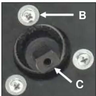
natural_image
Green circular device with black mounting holes and four rectangular cutouts (no text or symbols)Cappa aspirante:
natural_image
Close-up of a metallic flange with three small holes (no text or symbols visible)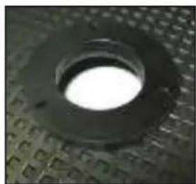
natural_image
Close-up of a circular mechanical component with a bright center, placed on a textured surface (no visible text or symbols)Piastra base
natural_image
Circular brown object with five white holes, no text or symbols visiblenatural_image
Simple line drawing of a trash bin with no text or symbolsSolo per i paesi UE
Frank Markert
Head of Engineering
Subject to change without notice.
Ihr Fachhändler Your distributor Votre distributeur Il Vostro rivenditore

- Wichtige Hinweise
- Absaughaube:
- Grundteller:
- Nur für EU-Länder
- Important Instructions
- Technical Data
- Supply
- Application for Indented Purpose
- Attention!
- Assembly
- Extraction hood:
- Base plate:
- Electrical Connection
- Switching on and off
- Short-Time Operation
- Permanent Operation
- Tool Change
- Dust Extraction
- Handling
- Do not touch rotating parts!
- Care and Maintenance
- Before the beginning of the maintenance or repair works you have to disconnect the plug from the mains.
- Environmental Protection
- Raw Material Recycling instead of Waste Disposal
- Only for EU countries
- Noise Emission
- Wear ear protectors!
- Warranty
- EU Declaration of Conformity
- Socle :
- Cappa aspirante:
- Piastra base
- Solo per i paesi UE
Brand : Eibenstock
Model : EWS 400
Category : Sander