JAOPX200 - Heat pump Jandy - Free user manual and instructions
Find the device manual for free JAOPX200 Jandy in PDF.
| Brand | JANDY |
| Model | JAOPX200 |
| Product Type | Pool water treatment system by ozonation and UV (AOP) |
| Supply Voltage | 240 V, 60 Hz |
| Rated Current | 0.6 A |
| Weight | 25.5 kg |
| Maximum Flow Rate | 189 L/min (50 gal/min) |
| Operating Ambient Temperature | 2 °C to 49 °C |
| Mounting Type | Floor or wall mounting |
| Number of UV Lamps | 2 |
| Ozone Modules Lifespan | 12,000 hours |
| UV Lamps Lifespan | 16,000 hours |
| Quartz Tube Replacement Interval | Every 6 months |
| Air Filter Replacement Interval | 1 year |
| Ozone Gas Line Replacement Interval | 1 year |
| Main Functions | Ozone and UV disinfection, chemical reduction, contaminant removal |
| Maintenance | Quartz tube cleaning, lamp and module replacement, filter inspection |
| Safety | Automatic shutdown if UV panel removed, flow switch, mandatory grounding |
| Spare Parts and Repairability | Ozone modules, UV lamps, quartz tubes, ballast, flow switch, ozone gas line |
| Warranty | Subject to regular maintenance according to recommended intervals |
Frequently Asked Questions - JAOPX200 Jandy
User questions about JAOPX200 Jandy
0 question about this device. Answer the ones you know or ask your own.
Ask a new question about this device
Download the instructions for your Heat pump in PDF format for free! Find your manual JAOPX200 - Jandy and take your electronic device back in hand. On this page are published all the documents necessary for the use of your device. JAOPX200 by Jandy.
USER MANUAL JAOPX200 Jandy
Jandy X Series™ AOP System
JAOPX500
WARNING
FOR YOUR SAFETY - This product must be installed and serviced by a contractor who is licensed and qualified in pool equipment by the jurisdiction in which the product will be installed where such state or local requirements exist. The maintainer must be a professional with sufficient experience in pool equipment installation and maintenance so that all of the instructions in this manual can be followed exactly. Before installing this product, read and follow all warning notices and instructions that accompany this product. Failure to follow warning notices and instructions may result in property damage, personal injury, or death. Improper installation and/or operation may void the warranty.

Improper installation and/or operation can create unwanted electrical hazard which may cause serious injury, property damage, or death.
ATTENTION INSTALLER - This manual contains important information about the installation, operation and safe use of this product. This information should be given to the owner/operator of this equipment.
Table of Contents
Section 1. Important Safety Instructions......3
Section 2. General Information.. 4
2.1 Description 4
2.2 Specifications. 4
Section 3. Installation 5
3.1 Tools 5
3.2 Pool Preparation.. 5
3.3 Location 5
3.4 Mounting 5
3.5 Plumbing 5
3.6 Electrical 7
Section 4. Operation.. 8
4.1 Initial System Start-Up 8
4.2 Normal Operation 8
4.3 System Shut-Down 8
4.4 Winterizing.. 8
4.5 Water Chemistry. 8
Section 5. Maintenance & Service. 9
5.1 System Electromechanical Overview 9
5.2 System Maintenance 9
5.3 Standard Replacement Parts List 11
5.4 Ozone System Maintenance 11
5.5 UV Reactor Service and Maintenance 12
Section 6. Troubleshooting 16
Section 7. Appendices.. 17
7.1 Appendix A: Jandy AOP X Series Installation - System Plumbing 17
7.2 Appendix B: Pressure Drop Curve 18
7.3 Appendix C: In-Place Quartz Tube Cleaning 18
EQUIPMENT INFORMATION RECORD
DATE OF INSTALLATION
INSTALLER INFORMATION
NOTES
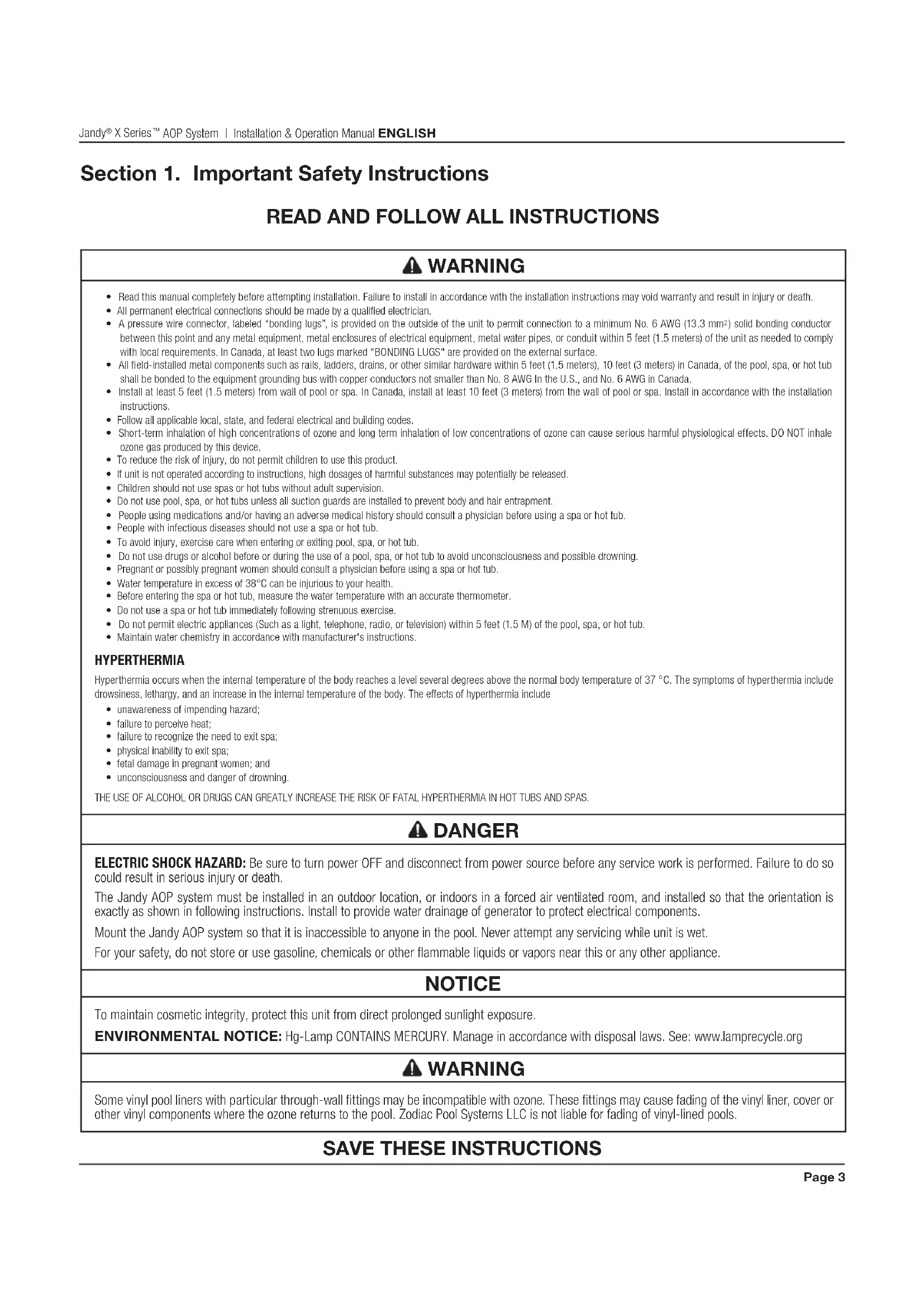
Section 1. Important Safety Instructions
READ AND FOLLOW ALL INSTRUCTIONS
WARNING
- Read this manual completely before attempting installation. Failure to install in accordance with the installation instructions may void warranty and result in injury or death.
- All permanent electrical connections should be made by a qualified electrician.
- A pressure wire connector, labeled "bonding lugs", is provided on the outside of the unit to permit connection to a minimum No. 6 AWG (13.3 mm²) solid bonding conductor between this point and any metal equipment, metal enclosures of electrical equipment, metal water pipes, or conduit within 5 feet (1.5 meters) of the unit as needed to comply with local requirements. In Canada, at least two lugs marked "BONDING LUGS" are provided on the external surface.
All field-installed metal components such as rails, ladders, drains, or other similar hardware within 5 feet (1.5 meters), 10 feet (3 meters) in Canada, of the pool, spa, or hot tub shall be bonded to the equipment grounding bus with copper conductors not smaller than No. 8 AWG in the U.S., and No. 6 AWG in Canada. - Install at least 5 feet (1.5 meters) from wall of pool or spa. In Canada, install at least 10 feet (3 meters) from the wall of pool or spa. Install in accordance with the installation instructions.
- Follow all applicable local, state, and federal electrical and building codes.
Short-term inhalation of high concentrations of ozone and long term inhalation of low concentrations of ozone can cause serious harmful physiological effects. DO NOT inhale ozone gas produced by this device.
To reduce the risk of injury, do not permit children to use this product. - If unit is not operated according to instructions, high dosages of harmful substances may potentially be released.
Children should not use spas or hot tubs without adult supervision. - Do not use pool, spa, or hot tubs unless all suction guards are installed to prevent body and hair entrapment.
People using medications and/or having an adverse medical history should consult a physician before using a spa or hot tub.
People with infectious diseases should not use a spa or hot tub. - To avoid injury, exercise care when entering or exiting pool, spa, or hot tub.
Do not use drugs or alcohol before or during the use of a pool, spa, or hot tub to avoid unconsciousness and possible drowning. - Pregnant or possibly pregnant women should consult a physician before using a spa or hot tub.
Water temperature in excess of 38^ can be injurious to your health.
Before entering the spa or hot tub, measure the water temperature with an accurate thermometer. - Do not use a spa or hot tub immediately following strenuous exercise.
Do not permit electric appliances (Such as a light, telephone, radio, or television) within 5 feet (1.5 M) of the pool, spa, or hot tub. - Maintain water chemistry in accordance with manufacturer's instructions.
HYPERTHERMIA
Hyperthermia occurs when the internal temperature of the body reaches a level several degrees above the normal body temperature of 37^. The symptoms of hyperthermia include drowsiness, lethargy, and an increase in the internal temperature of the body. The effects of hyperthermia include
- unawareness of impending hazard;
- failure to perceive heat;
- failure to recognize the need to exit spa;
- physical inability to exit spa;
- fetal damage in pregnant women; and
- unconsciousness and danger of drowning.
THE USE OF ALCOHOL OR DRUGS CAN GREATLY INCREASE THE RISK OF FATAL HYPERHERMIA IN HOT TUBS AND SPAS.
DANGER
ELECTRIC SHOCK HAZARD: Be sure to turn power OFF and disconnect from power source before any service work is performed. Failure to do so could result in serious injury or death.
The Jandy AOP system must be installed in an outdoor location, or indoors in a forced air ventilated room, and installed so that the orientation is exactly as shown in following instructions. Install to provide water drainage of generator to protect electrical components.
Mount the Jandy AOP system so that it is inaccessible to anyone in the pool. Never attempt any servicing while unit is wet.
For your safety, do not store or use gasoline, chemicals or other flammable liquids or vapors near this or any other appliance.
NOTICE
To maintain cosmetic integrity, protect this unit from direct prolonged sunlight exposure.
ENVIRONMENTAL NOTICE: Hg-Lamp CONTAINS MERCURY. Manage in accordance with disposal laws. See: www.lamprecycle.org
WARNING
Some vinyl pool liners with particular through-wall fittings may be incompatible with ozone. These fittings may cause fading of the vinyl liner, cover or other vinyl components where the ozone returns to the pool. Zodiac Pool Systems LLC is not liable for fading of vinyl-lined pools.
SAVE THESE INSTRUCTIONS
Section 2. General Information
2.1 Description
The JAOPX500 System described in this manual is designed to provide the benefits of ozonated and UV treated water in an environmentally safe and effective manner. The high quality, specially engineered components ensure efficient output and reliable performance. As a result of proper use, the JAOPX500 virtually eliminates the unpleasant effects of traditional chemicals. The Jandy AOP ozone generators are safe and harmless to your equipment when installed properly.
2.2 Specifications
Power Requirements:
240V, 60 Hz, 1Ω, 0.6 Amp
Shipping Weight:
Approx: 54lbs/25.5kg
Location Requirements:
Mounting: Floor Mounted
Ambient Temp.: 35^ - 120^ (2^ - 49^)
Max Flow Rate (for NSF 50 compliance):
189 LPM (50 GPM)
This product is designed for supplemental disinfection and should be used with registered or approved disinfection chemicals to impart residual concentrations.
Supplemental Disinfection - NSF/ANSI 50, section 13.19 disinfection efficacy testing for 3-log (99.9%) or greater of Enterococcus faecium [ATCC #6569] and Pseudomonas aeruginosa [ATCC #27313]. Specific residual levels of EPA registered disinfecting chemicals may be required by the regulatory agency having authority.
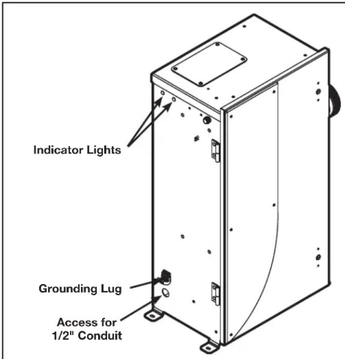
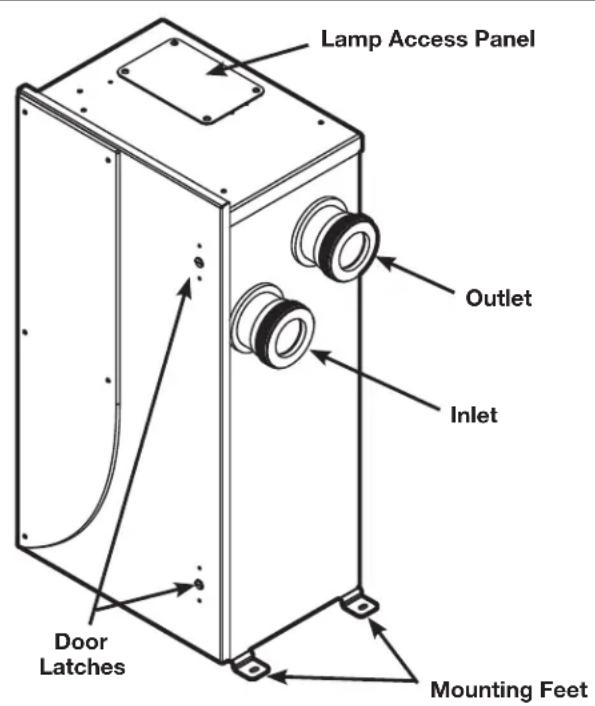
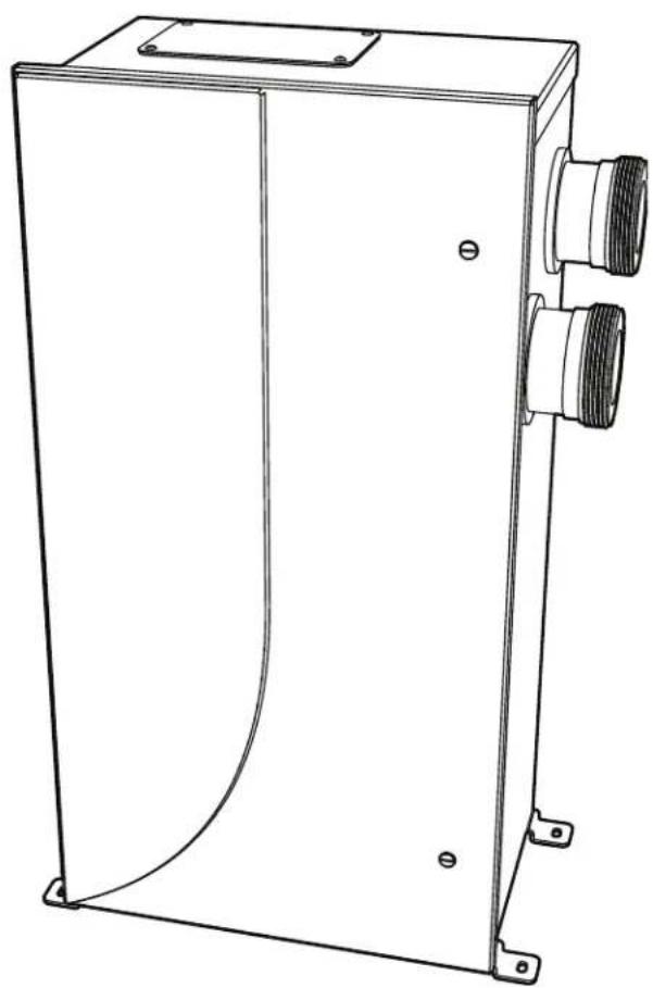
Figure 1. Overview
Section 3. Installation
3.1 Tools
- Cordless Drill
- Masonry drill bit, anchors or other appropriate fasteners
Wrench
3.2 Pool Preparation
To achieve optimal performance from the ozone system, the pool must be as clean as possible to start with.
- Backwash or clean filters one day before starting the ozone generator.
- Superchlorinate pool water using a chlorine based shock treatment so the water has a sustained 1-3 ppm free chlorine level.
- Test pool chemistry and adjust pH between 7.4 and 7.6. Adjust total alkalinity between 80 and 120~ppm
- Run pool filtration continuously for 24 hours prior to starting ozone system.
3.3 Location
Locate the Jandy AOP system in a clean, protected area, either indoors or outdoors (preferably out of direct sunlight). If possible, locate the unit out of reach of sprinklers or drainage spouts. Allow sufficient access for maintenance (2 ft clearance above and 1 ft around the unit) and all plumbing and electrical hookups.
3.4 Mounting
3.4.1 Floor Mounting
The Jandy AOP system is shipped with the mounting feet installed in the floor mounting position. Adjust the position of the feet if necessary and tighten the screws. Mount the Jandy AOP system to the equipment pad through the slots provided in the feet using appropriate hardware for the mounting surface.
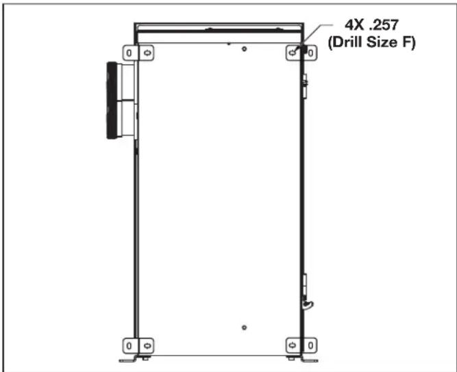
Figure 2. Wall Mounting Hole Pattern
3.4.2 Wall Mounting
The Jandy AOP unit does not have holes for wall mounting but can be mounted on the wall if desired.
- Drill 4 holes, (.257 in, drill size F), in the back of the enclosure approximately as shown in Figure 2.
- Open door as described in section Ozone Module Servicing and clean out debris.
- Install mounting feet in drilled holes with hardware provided.
- Mount unit to wall through the slots in the feet using appropriate hardware for the mounting surface.
3.5 Plumbing
The Jandy AOP system can easily be added into the pool's plumbing loop. All the components are contained inside the enclosure so only the water inlet and outlet need to be installed into the pool's return line.
3.5.1 Plumbing the JAOPX500 System
The Jandy AOP system must be installed in the pool's main return line after all other pool equipment (pump, filter, heater, and cleaner). The outlet of the AOP (or MDV Inline) must be at least 10 feet from the first return to the pool. Figure 3 shows the most basic installation. For installation with additional sanitizers and pool cleaners, refer to Appendix A.
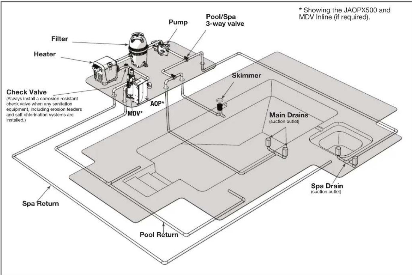
Figure 3. Typical Jandy AOP Location in Pool Plumbing Loop
The JAOPX500 will come with one half of a union fi tting installed on inlet and outlet, the other half of the fi ttings will be located in the Jandy AOP parts bag. Use the union fi ttings provided to connect the Jandy AOP inlet and outlet to your pool's plumbing as shown in Figure 3.
3.5.2 About the Mixing Degas Vessel (optional)
Under normal operations bubbles will appear in the return flow to the pool. To remove the bubbles from the flow, an accessory mixing degas vessel, or MDV, can be installed downstream of the Jandy AOP. The MDV Inline is designed for use with the JAOPX500 and is recommended on indoor, covered, or vinyl-lined pools. For more information, please call Technical Support.
NOTE: An MDV Inline may be recommended to reduce the chance of minor fading of the vinyl at the pool's ozone return fitting.
Some vinyl pool liners with particular throughwall fittings may be incompatible with ozone. These fittings may cause fading of the vinyl liner,
cover or other vinyl components where the ozone returns to the pool. Zodiac Pool Systems LLC is not liable for fading of vinyl-lined pools.
3.5.3 Water Backflow Check Valve
If the pool equipment is mounted above the water line, a check valve must be installed between the pump outlet and the injector manifold to prevent the pump from draining and losing its prime, when not in use.
3.5.4 Pressure Test
If a pressure test is required, it should be performed prior to installing the check valve assembly tubing connections. See Figure 6.
- Shut off power at the breaker.
- Shut off water to the unit.
-
Use a fl at blade screwdriver to turn the door latches counter clockwise and open the door.
-
Loosen or remove the tubing clamp on the injector tube adapter end of the ozone gas line. Use pliers (if necessary) to twist and unlock the clamp.
- Pull the tubing from injector tube adapter, then unthread the adapter from the injector manifold.
- Apply TeflonTM based thread sealant and install the injector cap into the injector manifold.
- Turn on pool circulation system and run at highest normal operating pressure.
- Check for leaks outside and inside of the Jandy AOP system. Correct any leaks outside of the system. Contact Customer Service for any internal leaks.
- Once the pressure test is complete, turn off the pool circulation system.
- Remove the injector cap. Re-thread the injector tube adapter into the injector manifold.
- Push the free end of the tubing into the injector tube adapter.
- Secure the tubing clamp on the injector tube adapter end of the ozone gas line. Use pliers (if necessary) to twist and lock the clamp.
- Use a flat blade screwdriver to turn the door latches counter clockwise and close the door.
- Turn on water and power at their sources.
3.5.5 Leak Test
Turn on pool circulation system and run at the highest normal operating pressure. Check for leaks outside and inside of the Jandy AOP system. Correct any leaks outside of the system. If any leaks are found inside the Jandy AOP, contact Customer Service.
3.6 Electrical
3.6.1 Main Power
Connect the Jandy AOP system to the pool timing clock so it operates simultaneously with the pool pump. The Jandy AOP system has an access hole for a 1/2'' conduit fitting. Install fitting (not provided) and run wire to terminal block inside unit. Remove the cover (refer to Ozone Module Servicing) and locate the terminal block (refer to Figure 5) on the left side of the enclosure. Connect Line 1, Line 2, and ground to the terminal block as indicated by the label on the generator bracket. Refer to the IMPORTANT SAFETY INSTRUCTIONS at the beginning of this manual for important wiring information.
3.6.2 Bonding and Grounding
CAUTION
This AOP system must be connected to a bonding grid with a solid copper wire not smaller in diameter than 8 AWG (In Canada, it shall be no smaller than 6 AWG.)
The National Electrical Code (NEC) in the United States) or the Canadian Electrical Code (CEC in Canada) requires pool equipment to be bonded to each other. Check your local codes to determine if the NEC or CEC and/or other local installation codes are enforced by the Authority Having Jurisdiction (AHJ in the United States) or the local competent authorities in Canada. A solid, copper 8.37mm^2 8AWG) wire is required per the NEC, and 13.3mm^2 6AWG per the CEC, for bonding the equipment to a permanent bonding connection that is acceptable to the local AHJ or the local competent authorities in Canada.
Refer to your locally enforced codes for the acceptable bonding wire gauge. Connect to the bonding point located on the bottom of the AOP system to a common bonding point. Do not use the AOP system as the common bonding point. Each piece of non-related pool equipment requiring a ground should also be bonded to the common, approved bonding point.
National Electrical Code® (NEC®) requires bonding of the Pool Water. Where none of the bonded pool equipment, structures, or parts are in direct connection with the pool water; the pool water shall be in direct contact with an approved corrosion-resistant conductive surface that exposes not less than 5800mm^2 (9 in²) of the surface area to the pool water at all times. The conductive surface shall be located where it is not exposed to physical damage or dislodgement during usual pool activities, and it shall be bonded in accordance with the bonding requirements of NEC Article 680. Refer to locally enforced codes for any additional pool and spa bonding requirements.
Section 4. Operation
4.1 Initial System Start-Up
Upon completing all of the system connections and cleaning the pool as outlined in the section Pool Preparation, you are ready to start the Jandy AOP system.
- Check electrical connections at breaker box.
- Turn on pool circulation system and verify the Jandy AOP system has power.
4.2 Normal Operation
Indicator Lights: The JAOPX500 has two external indicator lights on its left side. When the Jandy AOP system has power, the power indicator will illuminate. The flow indicator may be on momentarily. Once adequate water is flowing, the flow indicator will go out. If the flow indicator light is still lit after the pump has reached steady flow. Refer to Troubleshooting section.
4.3 System Shut-Down
The following sequence of steps must be followed for servicing or for storage.
- Shut off power at the breaker.
- Shut off water to the unit.
- Open door.
- Disconnect all electrical, plumbing, and mounting connections for storage.
4.4 Winterizing
If the pool will be shutting down for the winter months and the Jandy AOP system will remain exposed to freezing temperatures, the unit must be drained to prevent freeze damage to the wetted components. To drain the Jandy AOP system, see the following steps.
- If the Jandy AOP system is mounted below the water level, isolation valves must all be CLOSED to prevent excess water from draining into the unit.
- Open the door.
-
Locate the drain plug (refer to Figure 7) and remove to drain the remaining water in the Jandy AOP system.
-
Allow all the water to drain from the Jandy AOP system before threading the plug back into the UV reactor.
4.5 Water Chemistry
Regular chlorine testing should be performed as normal. Ozone will be eliminating the majority of contaminants. Therefore, only a small amount of chemicals will need to be added - just enough to maintain the appropriate residual level of free chlorine. Ozone is pH neutral and will not cause pH or total alkalinity fluctuations.
Section 5. Maintenance & Service
5.1 System Electromechanical Overview
CAUTION
Disconnect power before performing service. Refer to the Important Safety Instructions displayed in the front of this manual.
5.1.1 Ozone Modules
Each ozone module has a green light to indicate that the ozone power supply is operating properly.
5.1.2 Ultraviolet Lamps
There are two lamps in the UV reactor of the JAOPX500. A slight glow can be seen near the top of the lamps during normal operation.
5.1.3 Injector Manifold
Water flowing through the injector manifold generates the vacuum that draws ozone into the water. The spring loaded valve automatically adjusts for various water flow rates to keep the Jandy AOP system operating over a wide range of conditions.
5.1.4 Injector Tube Adapter
This connects the ozone gas line to the injector manifold. When servicing this component, do not tighten past 10 in-lbs or the component may be damaged.
5.1.5 Ozone Gas Line
Gas from the ozone modules is drawn through the ozone gas line by the Injector and into the water. The ozone check valve in this line prevents water from migrating back to the ozone modules when the Jandy AOP system is not running.
5.1.6 Ozone Module Filters
The air entering the ozone modules passes through individual filters on each module inlet. The filters are held in place by the rubber filter cap. (Refer to Figure 4 for a more detailed view.)
NOTE: Ballast located on enclosure ceiling not shown.
5.2 System Maintenance
Use a Phillips head screwdriver to remove the UV access panel or a flat tool to open the enclosure cover as needed.
NOTE: The Jandy AOP system will not operate until the UV access panel is replaced.
5.2.1 Ozone Module Maintenance
The green ozone module lights on the ozone modules indicate that the ozone power supply is operating properly. When an indicator light goes out, replace the corresponding ozone module.
5.2.2 Ozone Module Replacement Interval
Ozone module life expectancy is about 12,000 hours. Even if the ozone module light(s) are glowing, the ozone module may be producing little or no ozone after this period of time due to contamination within the corona discharge ozone chamber.
5.2.3 Ozone Gas Line Replacement Interval
Replace the ozone gas line every year or sooner, if needed. If there is evidence of water leaking past the ozone check valve toward the ozone modules, shut down the Jandy AOP system immediately and replace the ozone gas line. If water entered the ozone modules, run the filtration system so air will be drawn through the Pzone modules and they can dry out. Ozone modules will return to normal operation when dry.
WARNING
Trace amounts of nitric acid may be present in the ozone gas line. Wear proper safety equipment (gloves and eye protection) and avoid direct contact with any condensation in the line.
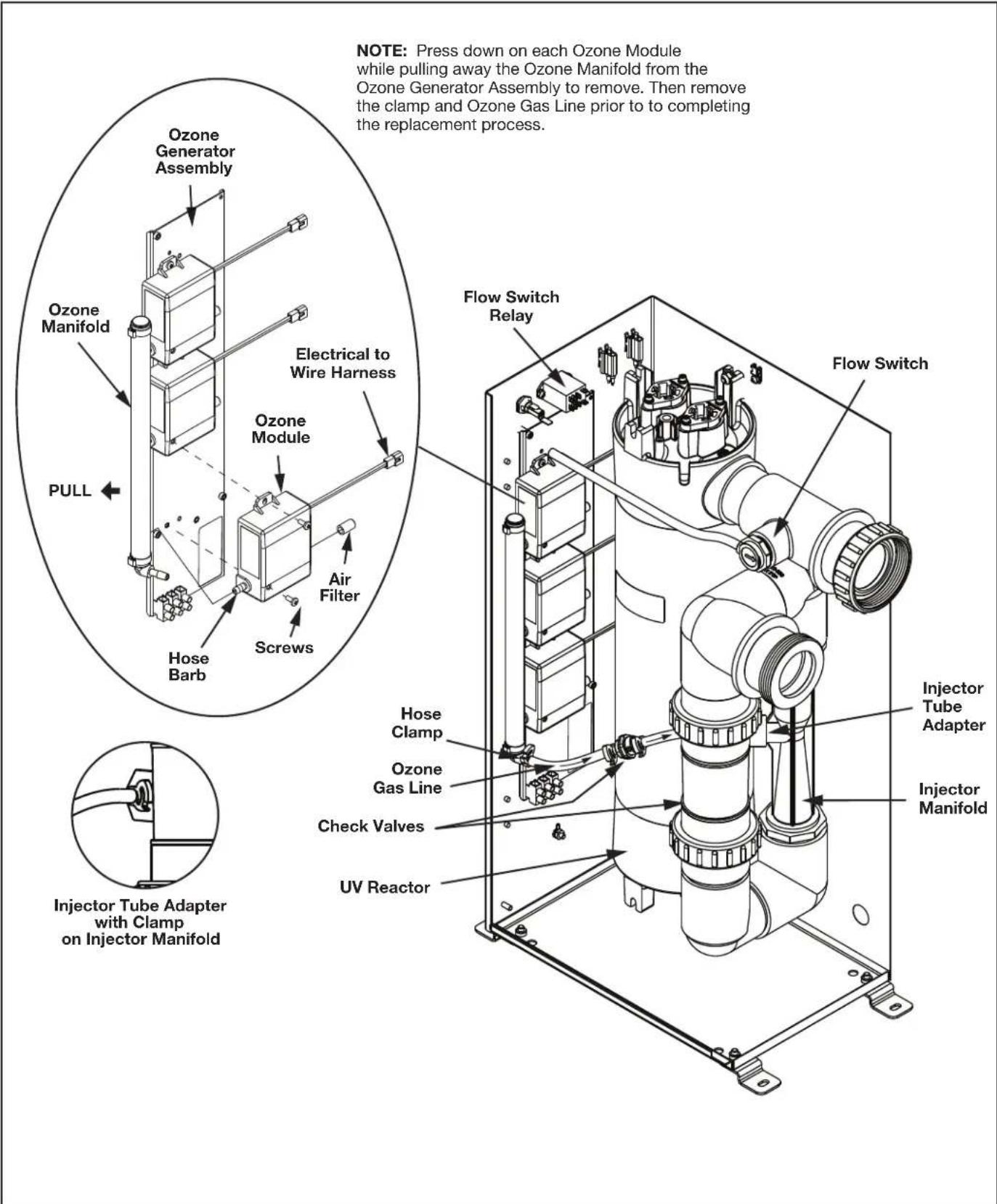
Figure 4. JAOPX500 Electro-Mechanical Assembly View
5.3 Standard Replacement Parts List
| Description Interval | val Part Number | R0992000 |
| Ozone Manifold Assembly | ||
| Flow Switch R0992100 | ||
| Ballast R0992200 | ||
| Ozone Module 12,000 | hours R0992300 | |
| Ozone Module Filter 1 | year | R0992300(included in kit) |
| UV Lamp 16,000 hours | R1014900 | |
| Quartz Tube 6 months | R1015000 | |
| Ozone Gas Line 1 year | R1015100 | |
| Air Filters (qty 3) | 1 year R10 | 91700 |
NOTE: The warranty may be voided if the parts listed above are not replaced at recommended intervals.
5.4 Ozone System Maintenance
5.4.1 Opening the Door
The Jandy AOP system may be serviced without disconnecting any of the plumbing or wiring. Simply use a flat blade screwdriver to turn the door latches counter clockwise and open the door. Reverse the steps to securely close the door.
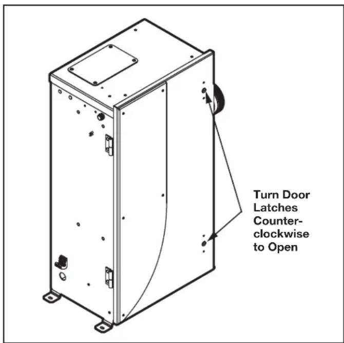
Figure 5. JAOPX500 Door Latches
5.4.2 Ozone Manifold Assembly Replacement
| WARNING |
| Trace amounts of nitric acid may be present in the ozone gas line. Wear proper safety equipment (gloves and eye protection) and avoid direct contact with any condensation in the line. |
- Shut off power at the breaker.
- Shut off water to the unit.
- Use a flat blade screwdriver to turn the door latches counter clockwise and open the door. See Figure 5.
- Hold each module in one hand while pulling the ozone manifold assembly away from the hose barb until it is fully disconnected from the ozone generator assembly and set aside. See Figure 4.
- Twist the hose clamp to unlock and disconnect the ozone gas line assembly from the hose barb located at the bottom of the ozone manifold assembly.
- Push the new ozone manifold assembly onto the hose barb of each ozone module assembly to secure into place.
- Push the ozone gas line assembly onto the hose barb at the bottom of the new ozone manifold assembly. Twist the hose clamp to lock.
- Turn power ON at the breaker.
- Close the door and turn the door latches to secure once the system is operational.
5.4.3 Ozone Module Replacement
| WARNING |
| Trace amounts of nitric acid may be present in the ozone gas line. Wear proper safety equipment (gloves and eye protection) and avoid direct contact with any condensation in the line. |
- Ozone module life expectancy is about 12,000 hours. All ozone modules should be replaced at the same time.
-
There is also an LED indicator on the ozone module itself. However, even if the ozone module light(s) are glowing, the module should be replaced. The ozone module may be producing little or no ozone after this period of time.
-
Shut off power at the breaker.
-
Use a flat blade screwdriver to turn the door latches counter clockwise and open the door. See Figure 5.
-
Locate the ozone modules on the left wall of the enclosure. See Figure 4.
- Remove the filter cap assembly from the right tube fitting of the ozone module. Keep the cap and filter together.
- Disconnect the ozone module by tracing the ozone module power wiring back to the nearest connector and by unlatching the connector.
- Remove the two (2) screws holding the ozone module to the mounting bracket using a Phillipshead screwdriver.
- While holding the ozone outlet manifold, gently pull the ozone module out of the manifold and out of the unit.
- If the filter needs to be replaced, reconnect the new air filter to the new ozone module.
- Push the new ozone module hose barb into the ozone manifold assembly.
- Reconnect the connector of new ozone module connector to the wire harness.
- Push the new ozone module onto the ozone outlet manifold and secure with the two (2) screws previously removed.
- Turn power ON at the breaker.
- Close the door and turn the door latches to secure once the system is operational.
5.4.4 Ozone Gas Tubing Replacement
The injector tube adapter connects the ozone tubing to the injector manifold. See smaller inset in Figure 4.
Gas from the ozone module is drawn through the ozone gas line by the injector and into the water. The ozone check valve in this line prevents water from migrating back to the ozone module when the system is not running. See Figure 4.
NOTE: When servicing this component, do not tighten past 10 in-lbs torque or the component may be damaged.
Replace the ozone gas line every year or sooner, if needed. If there is evidence of water leaking past the ozone check valve toward the ozone modules, shut down the Jandy AOP system immediately and replace the ozone gas line.
NOTE: Replace if worn or damaged.
WARNING
Trace amounts of nitric acid may be present in the ozone gas line. Wear proper safety equipment (gloves and eye protection) and avoid direct contact with any condensation in the line.
- Shut off power at the breaker.
- Shut off water to the unit.
- Use a flat blade screwdriver to turn the door latches counter clockwise and open the door. See Figure 5.
- Loosen or remove the tubing clamps both ends of the ozone gas line. Use pliers if necessary to twist and unlock the clamps. See Figure 5.
- Pull the tubing from the injector tube adapter connecting the injector manifold on the right side and the ozone outlet manifold on the left side of the Jandy AOP system.
- Orient ozone gas line as shown in Figure 4 (note flow direction callout), ensuring the gas flows towards the injector manifold. Re-connect onto the air barbs of the injector tube adapter on the right side and the ozone output barb on the ozone outlet manifold on the left side of the Jandy AOP system. Use pliers to secure all clamps previously removed or loosened.
- Turn power and water ON at their sources.
- Close the door and turn the door latches to secure once the system is operational.
5.5 UV Reactor Service and Maintenance
The JAOPX500 uses two (2) UV lamps housed in two (2) quartz tubes. If the quartz tube becomes dirty, its ability to transmit UV rays from the lamp will be diminished. If the UV lamp access panel is removed while the unit is running, the unit will be shut down automatically. For maximum UV treatment, replace the UV lamp after 16,000 hours of operation.
5.5.1 UV Lamp Replacement
NOTE: During the UV Lamp replacement, verify the Quartz Tube needs cleaning. If so, refer to R1015000 (JAOPX500) Quartz Tube Replacement Kit Instructions for further details.
- Shut off power at the breaker.
- Use a Phillips-head screwdriver to remove the four (4) screws holding the access cover. See Figure 6.
-
Before continuing, allow adequate time for the lamp to cool.
-
Disconnect the lamp connectors from the ballast wire connectors. Then grasp the UV lamp wires and gently pull until the top of the UV lamp has pulled past the lamp retainer tabs. See Figure 6.
NOTE: The lamp retainer and quartz tube do not need to be removed during the UV lamp replacement process. - While holding the UV lamp white ceramic cap, slowly pull the UV lamp until the bottom has pulled past the lamp retainer tabs. Twisting the lamp may help facilitate removal. Set aside and dispose per local disposal guidelines.
NOTE: Do not touch glass, as oils on your hands will damage the UV lamp. - Carefully insert the new UV lamp into the UV lamp retainer slot until the top ceramic cap is past the retainer tabs.
- Reconnect the connector of new UV lamp to the ballast wire connectors.
- Turn power ON at the breaker.
- Secure the UV lamp access panel using the four (4) screws once the system is operational.
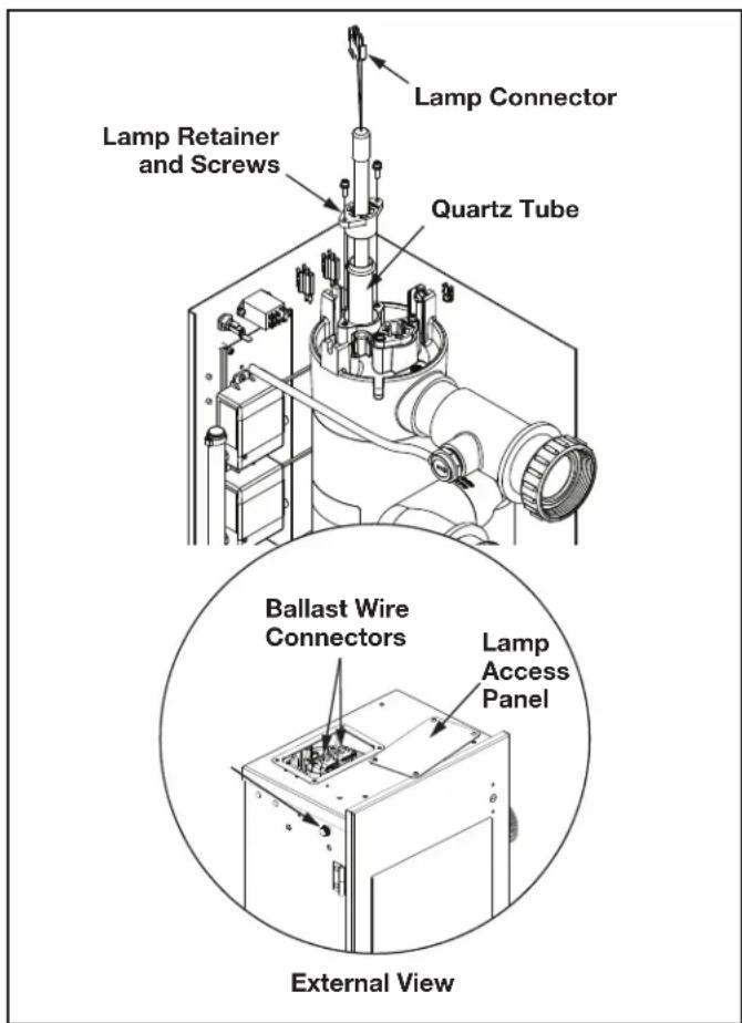
Figure 6. UV Reactor Sub-Assembly
5.5.2 Quartz Tube Removal and Cleaning (Every Six Months)
The UV lamps are housed in a quartz tube. If the quartz tube becomes dirty, its ability to transmit UV rays from the lamp will be diminished. The quartz tube(s) should be removed from the UV reactor every six (6) months and cleaned if necessary.
NOTE: If the Jandy AOP system is installed below water level, the bypass valves must all be CLOSED to prevent excess pool water from draining into the open unit when a quartz tube is removed.
NOTE: For instructions on cleaning without mechanical disassembly, see Appendix C.
- Shut off power at the breaker.
- Locate the UV lamp access panel on the top of the Jandy AOP system. Remove the four (4) screws with a Phillips head screwdriver, and remove the panel. See Figure 6.
- Before continuing, allow adequate time for the quartz tubes to cool. Drain the water from the UV reactor by removing the drain plug. Replace the plug once water has stopped exiting the UV reactor. See Figure 7.
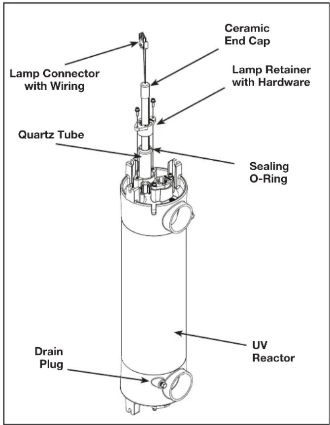
Figure 7. UV Reactor Sub-Assembly
- Grasp the UV lamp wires and gently pull until the top of the UV lamp has pulled past the lamp retainer tabs. See Figure 7.
- While holding the UV lamp white ceramic cap, slowly pull the UV lamp until the bottom has pulled past the lamp retainer tabs. Twisting the lamp may help facilitate removal. Set aside and dispose per local disposal guidelines.
NOTE: Do not touch glass, as oils on your hands will damage the UV lamp.
- After removing the lamps, remove the top lamp retainer screws using the hex key included in the parts bag. Place the lamp retainer screws, washers and the lamp retainer aside in a safe place. See Figure 7.
- Grasp the quartz tube from the top of the UV reactor. Pull to remove it from the UV reactor. See Figure 7.
- Remove the sealing O-ring from the top of the quartz tube. Set aside in a safe place. See Figure 7.
- Clean the quartz tube exterior with a mild solution of muriatic acid (available at all pool supply stores) and water in a ratio of four parts water to one part acid (4:1). If lime or hard water calcium deposits are encountered, use a household tub and shower lime remover.
- After cleaning the quartz tube, wash it off and wipe dry. Inspect the quartz tube for cracks. Replace if cracks are found. Make sure the inside of the quartz tube is dry before replacing the UV lamp(s).
CAUTION
Follow the directions for use and handling of muriatic acid on the acid bottle label, being careful to protect your eyes, wear rubber gloves, and avoid breathing acid fumes.
NOTE: DO NOT USE ABRASIVE CLEANERS as they can scratch the high quality quartz glass. If lime or hardwater calcium deposits are encountered, use household tub and shower lime remover. After cleaning the quartz tube, wash it off and wipe dry. Inspect the quartz tube for cracks. Replace if cracks are found. Make sure the inside of the quartz tube is dry before replacing the UV lamp(s).
NOTE: DAMAGES CAUSED BY BROKEN QUARTZ TUBES ARE NOT COVERED UNDER WARRANTY.
5.5.3 Quartz Tube Installation
- Hold the quartz tube so it is oriented straight up and down. Insert the quartz tube into the UV reactor until it is fully seated in the bottom of the UV reactor. See Figure 8.
NOTE: If the end of the quartz tube is protruding from the UV reactor, the alignment is off. Remove and re-insert the quartz tube to seat it properly. - Place a sealing o-ring approximately 1/2in (12.5mm) from the end of the quartz tube protruding from the top of the UV reactor.
- Place the lamp retainer over the quartz tube. Use the hex key included in the parts bag to attach the lamp retainer to the UV reactor, using the lamp retainer screws and washers. Torque lamp retainer screws to 15 in/lbs. Make sure the lamp retainer flanges are fully seated against the UV reactor. See Figure 8.
- Turn the circulation pump ON and check the quartz tube seal for leaks.
- Turn the circulation pump OFF once you have confirmed that the quartz tube is not leaking.
CAUTION
Wear proper eye and skin protection for servicing glass components. If broken glass is trapped in the pool system, do not operate the pool. Contact a service professional to have the glass removed.
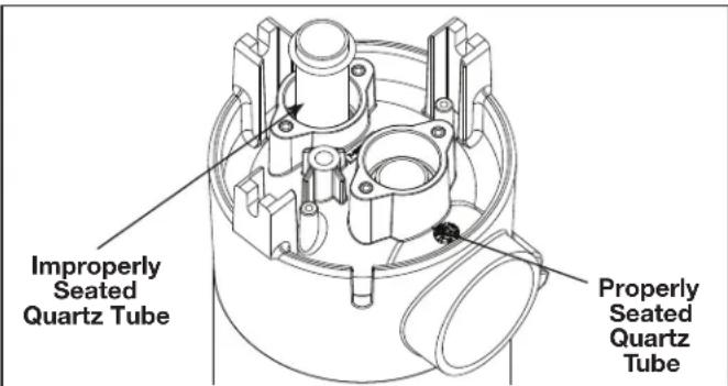
Figure 8. UV Quartz Tube Installation
5.5.4 Re-installing the UV Lamp(s)
NOTE: Make sure to handle the UV lamp as described in UV Reactor Service and Maintenance section.
- TURN OFF YOUR PUMP IF YOU HAVE NOT DONE SO.
-
Slowly press the UV lamp fully past the lamp retainer tabs and into the quartz tube until it is seated on the lamp cushion in the bottom of the tube.
-
Connect the lamp connector to the connector on the ballast.
NOTICE
ENVIRONMENTAL NOTICE: Hg-Lamp CONTAINS MERCURY. Manage in accordance with disposal laws. See: www.lamprecycle.org
5.5.5 Flow Switch Replacement
The Jandy AOP system must meet the minimum flow rate to activate the internal flow switch. Below this flow rate, the system will not turn on.
The Flow Switch Assembly can be found on the Injector Manifold Assembly gas and water flow plumbing line in a T-connector.
- Shut off power at the breaker.
- Shut off water to the unit.
- Use a flat blade screwdriver to turn the door latches counter clockwise and open the door.
- Disconnect the flow switch connectors from the flow switch relay above the ozone generator assembly. See Figure 9.
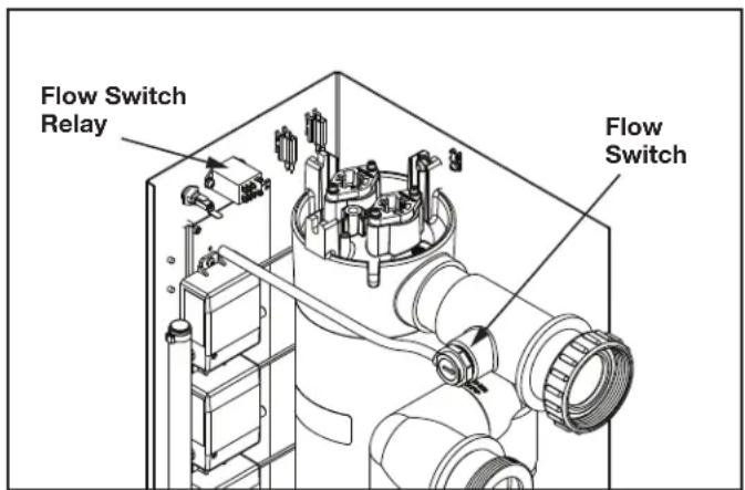
Figure 9. JAOPX500 Flow Switch and Electrical Relay Connection
- Unscrew the flow switch from the T-connector pipe housing.
- Carefully remove from its seat.
- Apply Teflon based thread sealant on the new flow switch and replace by screwing into pipe housing seat. Do NOT overtighten.
NOTE: Ensure flow switch is oriented such that the flow indication arrow is pointing toward the enclosure door.
- Reconnect the flow switch to the flow switch relay.
- Turn water and power ON at their sources and test the flow switch is operating correctly and that no leak is present.
- Close the door and turn the door latches to secure once the system is operational.
5.5.6 Ballast Replacement
The ballast regulates voltage, and provides proper current to the UV lamps. The ballast is mounted on the underside of the top of the enclosure.

WARNING
ELECTRIC SHOCK HAZARD: Be sure to turn power OFF and disconnect from power source before any service work is performed. Failure to do so could result in serious injury or death.
Never attempt any servicing while unit is wet.
- Shut off power at the breaker.
- Shut off water to the unit.
- Use a flat blade screwdriver to turn the door latches counter clockwise and open the door. See Figure 5.
- Locate the UV lamp access panel on the top of the Jandy AOP system. Remove the four (4) screws with a Phillips head screwdriver, and remove the panel. See Figure 6 External View.
- Before continuing, allow adequate time for the quartz tubes to cool.
- Disconnect the lamp connectors from the ballast wire connectors. See Figure 6.
- Disconnect all of the wiring connecting the Jandy AOP system to the ballast and secure away from the work area to avoid damaging the wiring.
- Unscrew the connection hardware to remove the old ballast and set aside.
- Secure the new ballast onto the underside of the top of the enclosure with the provided hardware.
- Reconnect all of the wiring connecting the Jandy AOP system to the ballast. See Figure 10.
- Reconnect the lamp connectors to the ballast wire connectors.
NOTE: Either lamp connector can be connected to either ballast wire connector.
- Replace the UV lamp access panel onto the top of the housing with the provided hardware. Close the door and turn the door latches to secure once the system is operational.
- Turn ON power and water at their sources.
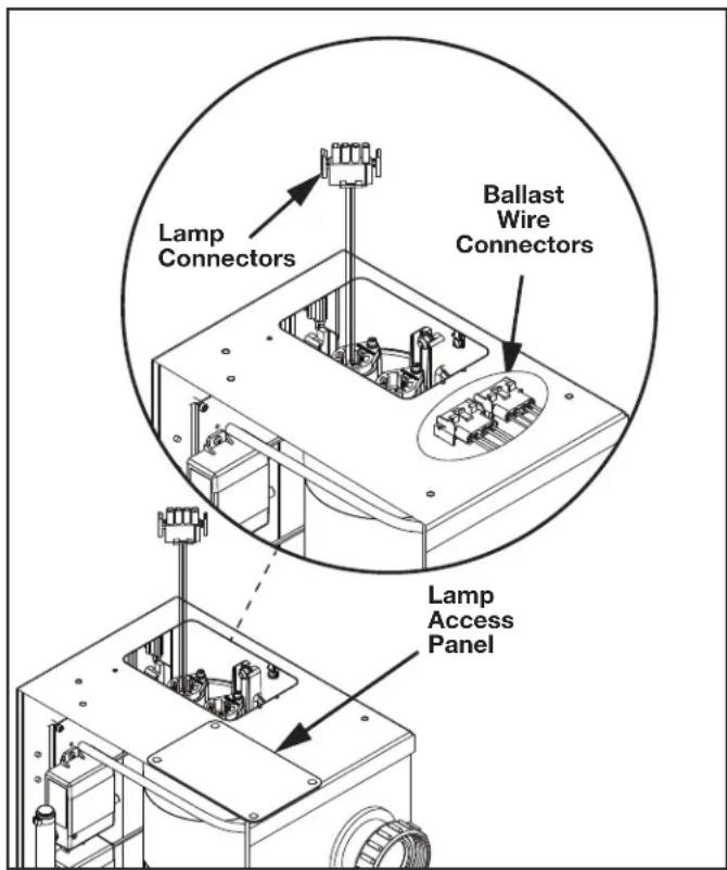
Figure 10. JAOPX500 UV Reactor Lamp Access
Section 6. Troubleshooting
Knowledge of electrical applications is required for trouble shooting. Contact a certified electrician if you are unsure of your ability to service the equipment. Improper servicing may void generator warranty. If any condition persists contact Technical Support at 800 922 7933.
Symptom: Power indicator not lit when pool system is on.
- No power to the Jandy AOP system from the power source:
a. Check circuit breaker at the power distribution box.
b. Check for loose connections or wiring breaks in the lines leading to the terminal block.
c. Fuse in the unit has blown and needs to be replaced. Fuse is a 1 amp slow blow, 1 / 4'' x 1.25" long, glass fuse.
d. The indicator light has burnt out.
Symptom: Flow indicator will not go out.
- Insufficient flow through Jandy AOP system.
a. Verify that pump is running properly and that filter and skimmers are clean.
b. Isolation valves are open, if installed.
- Clear any blockages in return line.
- Flow switch has failed and needs to be replaced.
- Flow switch relay has failed and needs to be replaced.
Symptom: Green ozone module light is not lit when unit is running.
- This means that the power supply of that specific ozone module is no longer drawing power and needs to be replaced. Refer to Ozone Module Servicing for instructions on how to replace the corresponding ozone module.
Symptom: One or both the UV lamps are not lit when unit it running.
- Check lamp connector plug for complete connection.
- Water fouling has shorted lamp connections.
- Bad UV lamp.
- Bad ballast.
Section 7. Appendices
7.1 Appendix A: Jandy AOP X Series Installation - System Plumbing
The Jandy AOP system works under vacuum. The injector in the Jandy AOP system draws the ozone/air gas mixture from the ozone cells and mixes it into the water leaving behind some un-dissolved gas bubbles. These bubbles can affect certain pool system components, so care must be taken when installing the Jandy AOP system.
The diagram covers common plumbing configurations. For other configurations or installation questions, please contact Technical Support.
- Pool Cleaners: (i.e. Polaris 360): Always plumb the cleaner t-fitting before the Jandy AOP system to prevent gas from affecting the operation of the cleaner.
- Salt Chlorinator: A salt chlorinator may be plumbed on either side of the Jandy AOP system.
- Chlorine Tab/Mineral Erosion Feeder: Always plumb the Jandy AOP system after any erosion feeder to avoid gas accumulating in the feeder. A corrosion resistant check valve must be installed between the feeder and the AOP system.
- In-Floor Cleaning System: The Jandy AOP system must be on a different pool return leg than any infloor cleaning system to avoid excess back pressure on the Jandy AOP system. This will also prevent gas intrusion and high oxidizer levels in zone valve and cleaner heads.
- Water Features: Avoid plumbing the Jandy AOP system into any leg with excessive back pressure such as those going to fountains, restrictive wall fittings, etc.
- Jandy AOP System: Back pressure on the system must be minimal.
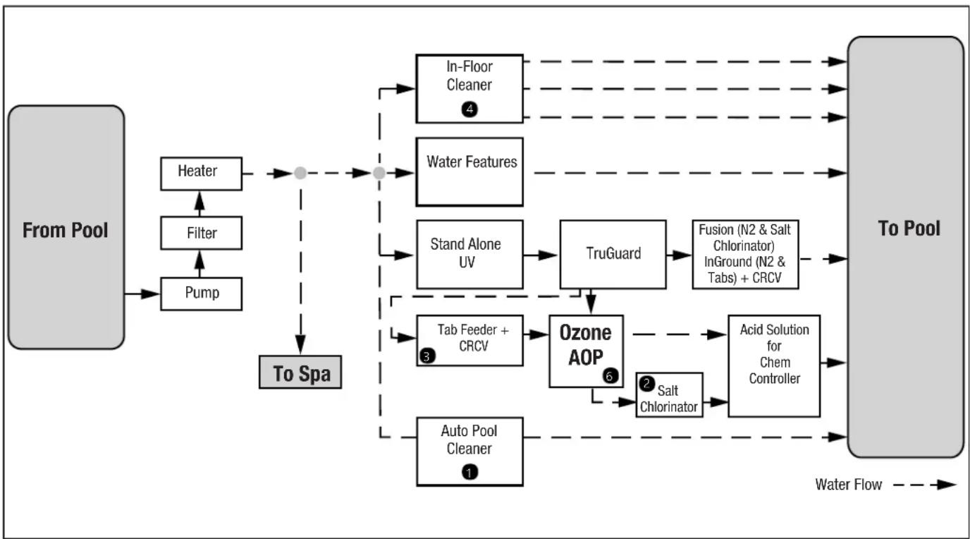
Figure 11. System Diagram
7.2 Appendix B: Pressure Drop Curve
Data source: 20140507_Solar Eclipse Back Pressure vs Flow.xlsx
Figure 12. Pressure Drop Over a Range of Flows

NOTE: Tested on simulated recirculation system using a 3HP variable speed pump. No back pressure added. Back pressure will raise the inlet pressure (filter pressure) but reduce the pressure drop slightly. Actual results will vary depending on pump and plumbing variables.
7.3 Appendix C: In-Place Quartz Tube Cleaning
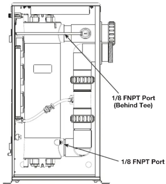
The JAOPX500 quartz tubes may be cleaned without removing them from the vessel. Ensure that the Jandy AOP system is isolated from the rest of the pool system with valves at the inlet and outlet (as shown in Figure 3). Use the 1/8'' FNPT ports at the top and bottom of the vessel to connect the cleaning system. Flow the cleaning solution from bottom to top.
When cleaning is complete, drain the Jandy AOP system completely from the bottom port and run the pool system immediately for an extended period to fully rinse the internal components. Special considerations may apply depending on the cleaning system. Contact Customer Service if there is any question about compatibility with the JAOPX500 components.
NOTES
2.1 Description 24
2.2 Specifications. 24
Section 3. Installation 25
Section 3. Installation
3.1 Outils
Le National Electrical Code (NEC) requires that the structure must be built in a similar way to the structure of the national electrical code. The structure must be built in a similar way to the national electrical code, but it should be built in a different way to the national electrical code.