
FF55T - Heating Toyotomi - Free user manual and instructions
Find the device manual for free FF55T Toyotomi in PDF.
| Product type | Oil heating (liquid fuel) with ventilated system |
| Brand | Toyotomi |
| Model | FF55T |
| Dimensions (W × H × D) | 496 × 600 × 339 mm |
| Weight | 20 kg (FF-55T) / 17 kg (FF-55) |
| Power supply | 230 V AC, 50 Hz (220 V AC, 50/60 Hz) |
| Electrical power (preheating) | Max 260 W |
| Electrical power (burning) | Max 48 W |
| Heat output (high) | 5.50 kW (18 800 BTU/h) |
| Heat output (medium) | 3.74 kW (12 800 BTU/h) |
| Heat output (low) | 1.88 kW (6 430 BTU/h) |
| Efficiency | 92.4 % |
| Fuel consumption (high) | 0.622 L/h |
| Fuel consumption (medium) | 0.423 L/h |
| Fuel consumption (low) | 0.213 L/h |
| Fuel type | Kerosene (paraffin) only |
| Fuel system | Removable tank (7.6 L) or external tank (optional) |
| Ventilation tube opening | 70 ~ 80 mm diameter |
| Max ventilation tube length | 3 m, max 3 bends |
| Safety devices | Flame detector, overheat protection, child lock, full ventilated system |
| Main functions | Weekly timer (4 programs/day), energy saving mode, automatic burner cleaning, manual mode (3 power levels), optional WiFi |
| Routine maintenance | Clean louvers (1x/week), air filter (1x/week), fuel filter (1x/month), check leaks |
| Available spare parts | Hose extension kits (S, M, L), WiFi module, seals, filters, manual pump |
| Repairability | Maintenance by authorized technician recommended; error codes for simplified diagnosis |
| General information | Exterior wall installation mandatory; do not use gasoline; max altitude 1000 m (up to 1500 m with intervention) |
Frequently Asked Questions - FF55T Toyotomi
User questions about FF55T Toyotomi
0 question about this device. Answer the ones you know or ask your own.
Ask a new question about this device
Download the instructions for your Heating in PDF format for free! Find your manual FF55T - Toyotomi and take your electronic device back in hand. On this page are published all the documents necessary for the use of your device. FF55T by Toyotomi.
USER MANUAL FF55T Toyotomi
natural_image
Two white industrial air purifiers with digital display and ventilation grilles, one labeled 'nivindust' (no other text or symbols visible)GB OPERATING MANUAL ...... PAGE 1
For the Operate WiFi mode
The WiFi mode needs to purchase optional parts that are not standard installation.
Please contact to your dealer for purchase the following option parts.
Use only genuine TOYOYOMI parts for your heater. Use of unauthorized, generic or other brands parts can severely reduce performance and safety, and will void factory warranty.
Only your dealer can install the WiFi module in your heater. DO NOT install the WiFi module to heater by yourself.
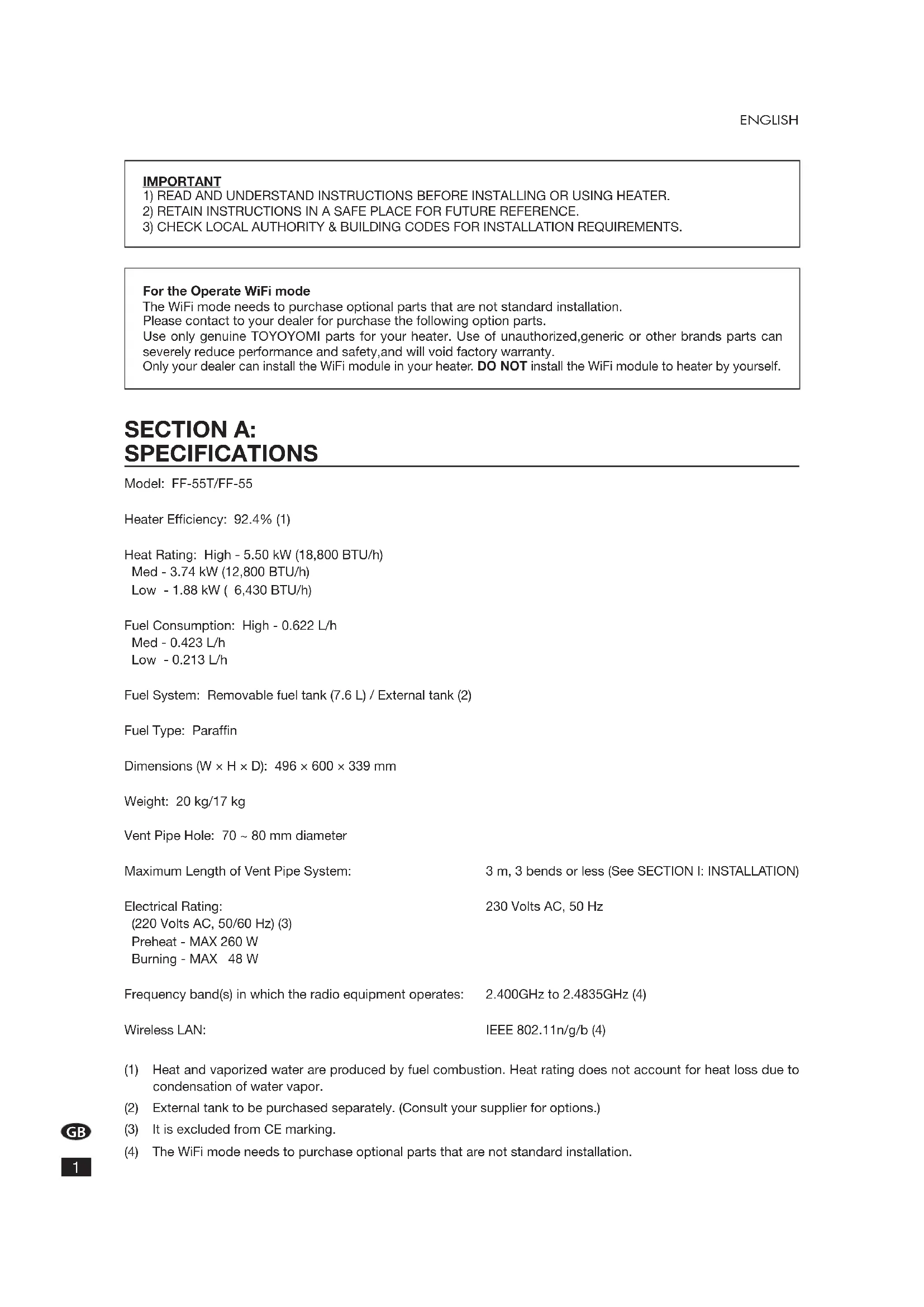
SECTION A: SPECIFICATIONS
Model: FF-55T/FF-55
Heater Efficiency: 92.4% (1)
Heat Rating: High - 5.50 kW (18,800 BTU/h)
Med - 3.74 kW (12,800 BTU/h)
Low - 1.88 kW (6,430 BTU/h)
Fuel Consumption: High - 0.622 L/h
Med - 0.423 L/h
Low - 0.213 L/h
Fuel System: Removable fuel tank (7.6 L) / External tank (2)
Fuel Type: Paraffin
Dimensions (W × H × D): 496 × 600 × 339 mm
Weight: 20 kg/17 kg
Vent Pipe Hole: 70 \~ 80 mm diameter
Maximum Length of Vent Pipe System: 3 m, 3 bends or less (See SECTION I: INSTALLATION)
Electrical Rating: 230 Volts AC, 50 Hz
(220 Volts AC, 50/60 Hz) (3)
Preheat - MAX 260 W
Burning - MAX 48 W
Frequency band(s) in which the radio equipment operates: 2.400GHz to 2.4835GHz (4)
Wireless LAN: IEEE 802.11n/g/b (4)
(1) Heat and vaporized water are produced by fuel combustion. Heat rating does not account for heat loss due to condensation of water vapor.
(2) External tank to be purchased separately. (Consult your supplier for options.)
(3) It is excluded from CE marking.
(4) The WiFi mode needs to purchase optional parts that are not standard installation.
SAFETY FEATURES
Your heater is equipped with the following safety features.
Please familiarize yourself with these features.
When your heater is extinguished due to a safety mechanism, be sure to identify the problem correctly.
FF-55TFF-55
1. Flame Sensor
Heater will automatically stop all operations if ignition fails or if flame fails during combustion, in order to prevent fuel overflow. Error code will be displayed on the operation panel.
2. Fuel Strainer (FF-55)
Special strainer catches dirt or impurities present in the fuel before it is sent to the burner.
3. Overheat Protector
Automatically stops all operations if the heater's inside cabinet reaches abnormally high temperature due to motor malfunction or abnormal combustion, in order to prevent fire.
4. Power Failure Recovery System
If power fails during heater operation, heater will automatically reignite and maintain the selected temperature, when power resumes.
NOTE: The operation varies depending on the time length of power failure and other conditions.
(See SECTION E : OPERATION)
5. Fully Vented System
Flue Pipe system uses outside air for combustion and vents all combustion products to outdoor.
SECTION B:
CAUTION: Heater and vent pipe system must be properly installed before operation.
Please follow instructions under SECTION I: INSTALLATION.

natural_image
Cartoon illustration of a smiling computer with a pencil and sparkles (no text or symbols)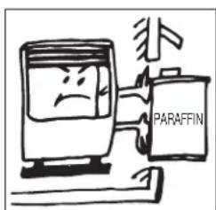
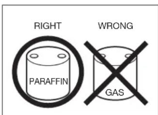
- NEVER use any fuel other than Paraffin. NEVER USE GASOLINE. Use of gasoline can lead to uncontrollable flames, resulting in destructive fire.
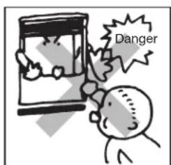
- Due to high surface temperatures, keep heater away from children, furniture and clothing while in operation. (See Installation manual.)
- The appliance is not to be used by persons (including children) with reduced physical, sensory or mental capabilities, or lack of experience and knowledge, unless they have been given supervision or instruction.
- Children being supervised not to play with the appliance.
- This appliance can be used by children aged from 8 years and above and persons with reduced physical, sensory or mental capabilities or lack of experience and knowledge if they have been given supervision or instruction concerning use of the appliance in a safe way and understand the hazards involved.
• Children shall not play with the appliance. -
Cleaning and user maintenance shall not be made by children without supervision.
-
To prevent abnormal operation and prolong heater life, be sure to perform routine maintenance.
(See SECTION F: ROUTINE MAINTENANCE)
- NEVER store or transport fuel in other than a metal or plastic container that is acceptable for fuel and clearly marked "PARAFFIN". NEVER store fuel in the living space.
Defective electrical devices and batteries must be kept separate from household waste. Ensure that there is effective recycling where possible. Ask you local council or dealer for expert advice on recycling.
SECTION C: FUEL GUIDE
The FF-55T/FF-55 is designed for use with Paraffin. Use of low-quality fuel will cause burner performance to drop, leading to abnormal combustion and reduced heater life.
Purchase only Paraffin, in cans reserved exclusively for fuel and marked accordingly with the word "PARAFFIN". Always store your fuel in a separate area from where you store gasoline for your power equipment to avoid accidental use of gasoline in your heater.
What to Buy ...
ALWAYS: Clean and high-quality Paraffin.
ALWAYS: Fuel free of contaminants, water or cloudiness.
NEVER: Gasoline, alcohol, white gas, camp stove fuel or additives.
NEVER: Yellow or sour-smelling fuel.
How to Store It ...
ALWAYS: Store in a clean container, clearly marked PARAFFIN.
ALWAYS: Store away from direct sunlight, heat sources or extreme temperature changes.
NEVER: In a glass container, or one that has been used for other fuels.
NEVER: For longer than six months. Begin each heating season with fresh fuel; discard at the end of season.
NEVER: In the living space.
Why It is Important . . .
Pure, clean fuel is essential for safe and efficient heater operation. Poor quality or contaminated fuel can cause:
- Excess tar deposits on burner and flue pipe
• Incomplete combustion - Reduced heater life
Use of a highly volatile flammable fuel such as gasoline can produce uncontrollable flames, creating a severe fire hazard.
SECTION D:
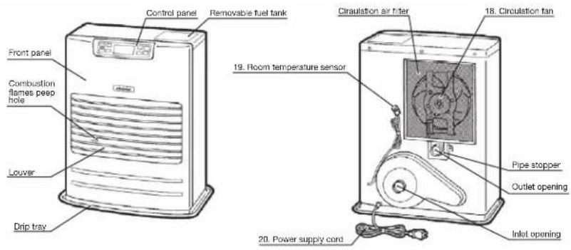
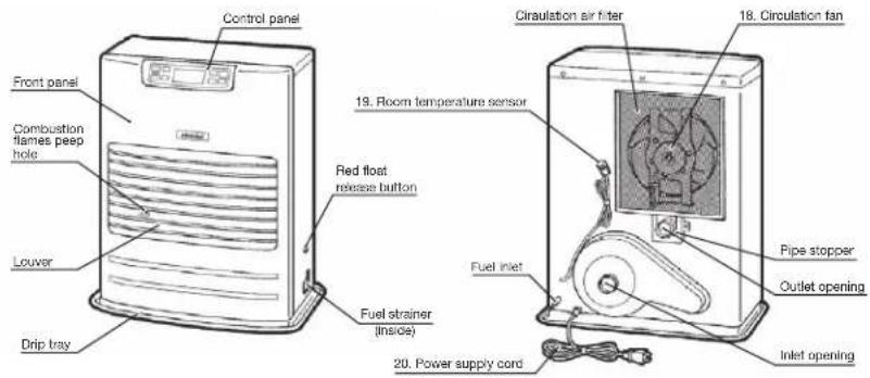
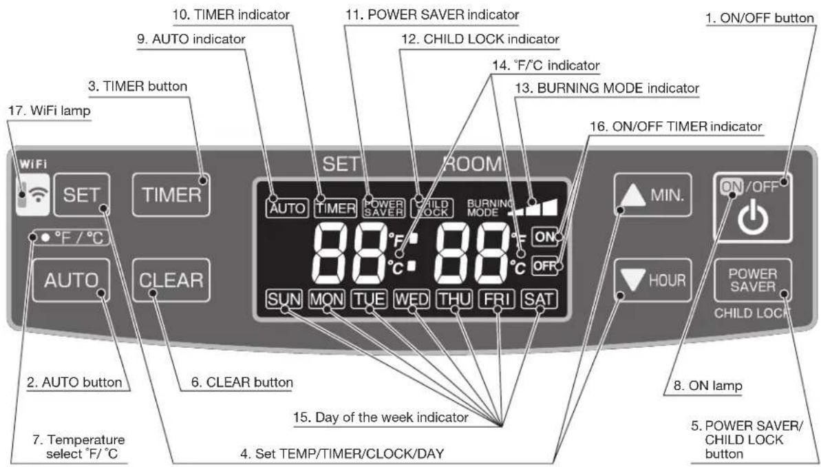
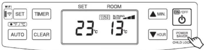
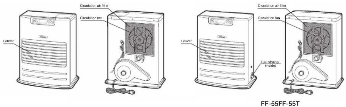
OPERATING CONTROLS AND PART NAMES
Before using heater, familiarize yourself with the following operating controls and part names.
FF-55T
FF-55
-
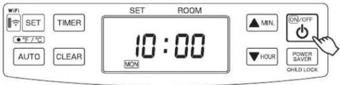
ON/OFF button Main button switch turns heater on and off. When switched on, heater begins operation and combustion starts after preheat period.
-
AUTO button The button turns weekly timer operation modes on and off which have been programmed into weekly timer.
-
TIMER button The button turns weekly timer set mode on and off.
-
SET button To set TIME/TEMP/WEEKLY TIMER/ and Day of week.
-
POWER SAVER/CHILD LOCK button The button turns POWER SAVER operation mode on and off. Press and hold the button, to turn on or off CHILD LOCK mode.
-
CLEAR button When reset the program for weekly timer, the CLEAR button is used.
-
Temperature select °F/°C °F/°C toggle switch.
-
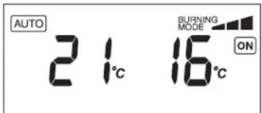
ON lamp Lit - Heater is in operation. Flashing - Pre-heating and pre-purging.
-
AUTO indicator Lit – Weekly timer operation is in use.
-
TIMER indicator Lit - Heater operating in weekly timer set mode.
| 11. POWER SAVER indicator | Lit – Heater operation in POWER SAVER mode. |
| 12. CHILD LOCK indicator | Lit – Heater operation in CHILD LOCK mode. |
| 13. BURNING MODE indicator | Lit – Heater operation at high, medium or low combustion. |
| 14. °F/°C indicator | Lit – Display shows current temp. |
Flashing – Current temp can be changed.
-
Day of the week indicator Lit – Display shows current day or timer day.
-
ON/OFF TIMER indicator Lit – Display ON/OFF of weekly timer mode.
-
WiFi lamp Lit – The heater in WiFi mode.
-
Circulation fan Three speed motor supplies high-capacity warm air flow during high combustion for quickly heating up a room, and low or medium-capacity warm air flow during low or medium combustion for maintaining comfortable room temperature.
-
Room temperature sensor Constantly senses room temperature and supplies information to heater so that desired room temperature can be maintained.
-
Power supply cord For use in proper electrical outlet. (See SECTION A: SPECIFICATIONS)
BEFORE IGNITION
1. Filling Fuel
FF-55T:
- Do not fill the removable tank in the living room, but in a more suitable place (there can always be some spillage).
- Do not refuel the heater while in operation or still hot.
Follow the procedure below:
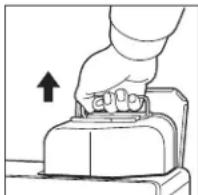
1) Make sure that the heater is switched off.
2) Open the tank lid and lift the removable tank out of the heater.
NOTE: Some drops may leak from the tank. Put down the removable tank (cap pointing upwards) and screw off the fuel cap.
3) Take the manual fuel pump and insert the smooth, most rigid tube into the can.
Make sure that it is in a higher position than the removable tank. Insert the ribbed hose into the opening of the removable tank.
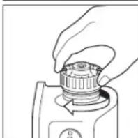
4) Lock the switch button on top of the pump (turn clockwise).
5) Squeeze the pump a few times, until fuel starts flowing into the removable tank.
As soon as this happens, there is no need to press any longer.
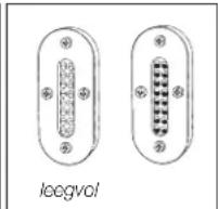
6) Check the removable tank fuel gauge while filling the tank. Stop filling by loosening the switch button on top of the pump (turn anticlockwise), once the gauge indicates that the tank is full. Never overfill the tank, especially not when the fuel is very cold (fuel expands when it heats up).
7) Let the remaining fuel in the pump flow back into the can and carefully remove the pump. Carefully screw the fuel cap back on the tank. Clean off any spilled fuel.
8) Check whether the fuel cap is straight an tightened properly. Reinstall the removable tank in the heater (cap down). Close the tank lid.
natural_image
Illustration of a hand pressing a button on a mechanical component (no text or symbols)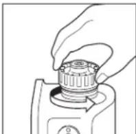

natural_image
Diagram of a gas collection or storage system with a coiled tube and container (no text or symbols)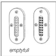

natural_image
Line drawing of a hand pressing down on a mechanical component (no text or symbols)
FF-55:
1) Open the Valve(s)
Open the valve(s) of the external fuel tank.
2) Start the Fuel flow
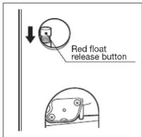
If using heater for the first time, press the red float release button in order to end fuel to the fuel sump and release.
NOTE: Make sure there is no fuel leakage from the fuel line or joints. Also make sure fuel tank is not too high. See installation instructions.
NOTE: Red Float Release Button is for first time installation, or on rare occurrences when the fuel tank is filled. This red button is to release the fuel sump float. It does not prime the fuel into the sump. Pushing the Red Float release Button, too many times or for too long of a period WILL cause flooding of the fuel sump, which can result in a possible fire. Only every push the Red Float release Button once, with a quick press of less than one second.
2. Plug in the Heater
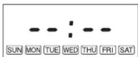
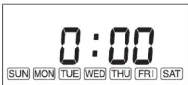
Plug in heater into 220V or 230V AC electrical outlet. (See SECTION A: SPECIFICATIONS). On Display pre-set "Two Dashes" will be showing. NOTE: Do not connect to an outlet shared with other appliances.
3. Set Clock
IMPORTANT: Clock on the heater must always be set to current time and day.
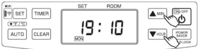
NOTE: “▼HOUR” or “▲MIN.” button will change the time every one (1) unit. Holding the button continuously will cause the time to change rapidly.
NOTE: In the event of a power failure (more than approx. 30 min.), all clock and day may be cancelled.
4. Setting of the Time and a Day of the Week.
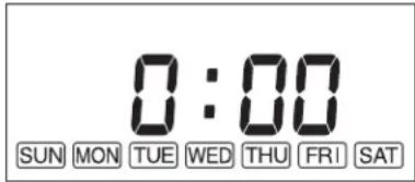
1) Current time is not set yet. (All signs light on solid.)
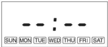
When the “▲MIN.” button or “▼HOUR” button is pressed while the operation is stopped, all displays except the colon “:” will be blinking.
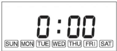
When the “▲MIN.” Button or the “▼HOUR” button is pressed again, the bar display (“Two Dashes”) changes to “0 00”
2) Setting of the current time
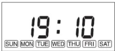
Press the “▲MIN.” button to set minutes and press the “▼HOUR” button to set hours.
When pressing the “▼HOUR” button, the sign will change as follows.
When pressing the “▲MIN.” button, the sign will change as follows.
“0:00”→“0:01”→…→“0:59”→“0:00”→…
Press the "SET" button to complete the set of the current time.
3) Setting of a day of the week
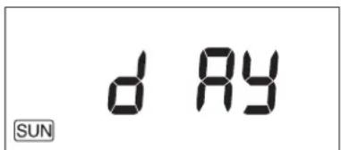
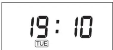
“dAy” sign is shown on the display and day of the week will blink.
Press the “▲MIN.” button or the “▼HOUR” button to set a day of the week. A day of the week will blink. (Initial setting is “SUN”). The other days of the week will go off. Select a day of the week by using the “▲MIN.” or the “▼HOUR” button. When pressing the “▲MIN.” button, the sign will change as follows.
“SUN” → “MON” → “TUE” → “WED” → “THU” → “FRI” → “SAT”
When pressing the “▲MIN.” button at the position of “SAT”, you can hear a beep sound and “SAT” is not changed any more. When pressing the “▼HOUR” button, the sign will change as follows.
“SAT” → “FRI” → “THU” → “WED” → “TUE” → “MON” → “SUN”
When pressing the “▼HOUR” button at the position of “SUN”, you can hear a beep sound and “SUN” is not changed any more.
Press the “SET” button to complete the setting of the days of the week. The current time and a day of the week will show on the display.
NOTE: In case, ON/OFF button is pressed while the time and day is setting, the setting will not be completed. Set the time and day again.
OPERATION
MANUAL OPERATION
Operation of the heater is under the direct control of the user. Heat output will, however, be automatically adjusted in accordance with the room temperature registered by the temperature sensor.
1. Turning Heater ON
A. Press ON/OFF button to "ON" position. The current room temperature and the set temperature will be shown on the Display. If the room temperature is below the set temperature then, ON lamp will start to flash and then
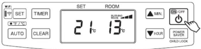
blower motor and ignition will start. This lamp will continue to flash during the preheating time.
B. Pre -heating depends on the room temperature. After approx. 1.5 – 4 minutes ignition will take place. (*) After ignition, ON lamp will change flashing to continuous. Circulation fan will turn on after approx. 2 minutes.
NOTE: (*) Pre -heating depends on the room temperature.
Room temperature:
below 0°C Approx. 4 minutes
0°C - 15°C Approx. 2 minutes
15°C Over Approx. 1.5 minutes
2. Adjusting Room Temperature
A. Press “▲MIN.” or “▼HOUR” button. °F or °C will start to flash.
NOTE: “▲MIN.” or “▼HOUR” button will change the temperature in increment of 1°C (2°F).
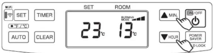
B. Press “▲MIN.” for up and “▼HOUR” for down. Room temperature can be set from 10°C (50°F) to 32°C (90°F). (Initial setting : 13°C (56°F))
C. When room temperature reaches the selected setting, heater will automatically shift to "MED" or "LOW" burning mode to maintain the desired temperature.
When room temperature exceeds the selected setting by approx. 2^ C ( 4^ F), the heater will automatically shut off. As room temperature drops, the heater will automatically re-start to maintain the desired temperature.
The Power Saver mode reduces the frequency of ignition actions, to save electric consumption.
- Press the POWER SAVER (CHILD LOCK) button "ON" while in operation to start the operation of the "POWER SAVER". "POWER SAVER" sign will be shown on the display.
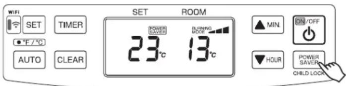
When the room temperature exceeds the selected setting by approximately 6^ C ( 12^ F), the heater will automatically shut off. As the room temperature becomes lower than the selected setting, the heater will automatically re-start to maintain the desired temperature.
FUEL INDICATOR LIGHT (FF-55T)
When the information display lights up, FU 10, it means that there is only fuel left for 10 more minutes. The count down of the remaining heating time can be seen in the information display. You remove the fuel tank and refill it outside the living room. If you don't refill it, you will hear an alarm signal every two minutes, warning you to refill the removable tank. After 10 minutes the information display, FU EL, blinks and the heater will switch off automatically.
FU 10
FU EL
The childproof lock can be used to prevent children accidentally changing the heater settings. When the heater is burning and the childproof lock is on, the heater can only be switched off. Other functions are blocked then. If the heater has already been
switched off, the childproof lock also prevents accidental ignition of the heater.
- Press and hold the CHILD LOCK (POWER SAVER) button for more than 3 seconds to set the child lock while in operation or not in operation. "CHILD LOCK" sign will be shown on the display.
To release the child lock operation, press the CHILD LOCK (POWER SAVER) button for more than 3 seconds.
1. Weekly Schedule setting
NOTE: The following Weekly Schedule is set by the factory. This programming can be changed.
| P01 P02 P03 P | 04 | |||||||||||
| Day TIME | ON/OFF | SET temp. | TIME | ON/OFF | SET temp. | TIME | ON/OFF | SET temp. | TIME | ON/OFF | SET temp. | |
| MON | 6:30 | ON | 21°C | 8:00 | ON | 18°C | 18:00 | ON | 21°C | 22:30 | ON | 16°C |
| TUE | 6:30 | ON | 21°C | 8:00 | ON | 18°C | 18:00 | ON | 21°C | 22:30 | ON | 16°C |
| WED | 6:30 | ON | 21°C | 8:00 | ON | 18°C | 18:00 | ON | 21°C | 22:30 | ON | 16°C |
| THU | 6:30 | ON | 21°C | 8:00 | ON | 18°C | 18:00 | ON | 21°C | 22:30 | ON | 16°C |
| FRI | 6:30 | ON | 21°C | 8:00 | ON | 18°C | 18:00 | ON | 21°C | 22:30 | ON | 16°C |
| SAT | 8:00 | ON | 21°C | 10:00 | ON | 18°C | 18:00 | ON | 21°C | 23:00 | ON | 16°C |
| SUN | 8:00 | ON | 21°C | 10:00 | ON | 18°C | 18:00 | ON | 21°C | 23:00 | ON | 16°C |
NOTE: The current time and day of the week must be set first before the Weekly schedule settings can be changed.
NOTE: The Weekly schedule settings cannot be entered or changed while the heater is ON and in AUTO mode. Turn "AUTO" off. It does not matter if the heater is OFF or ON to enter the Weekly schedule settings mode, as long as the AUTO is off.
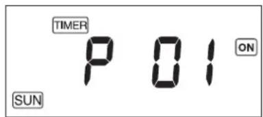
Program Selection
-
Press the "TIMER" button to enter the weekly schedule settings mode. The word "TIMER", "SUN", "P01" and "ON" will be shown on the display.
If you press the "TIMER" button while in the weekly schedule settings mode, the word "TIMER" will disappear from the screen and the weekly schedule settings mode will be exited. Any changes before the "SET" button was pressed will not be saved.
If the heater is turned off during the weekly setting mode, the weekly schedule setting mode will be exited. -
Press the “▲MIN.” or “▼HOUR” button to change the program number you with to set or modify. The programs range from P01 to P04 for each day of the week, starting with Sunday and ending with Saturday (The heater has 4 programs for each day). When pressing the “▲MIN.” button, the display will change as follows.
"SUN P01" → "SUN P02" → "SUN P03" → "SUN P04" → "MON P01" → "MON P02" → ... → "SAT P04" NOTE: When the "▼HOUR" button is pressed while at the bottom of programming which is P01 on Sunday (SUN), the program number cannot be changed. If you press the "▲MIN." button while on P04 on Saturday (SAT), which is the top of the programming, the program number cannot be changed.
- Press the "SET" button to confirm changes and to go to the Program Time Settings. The program number is initialized by pressing and holding the "CLEAR" button for 3 seconds. It is not necessary to initialize the memory if you plan to change it.
Program Time Settings
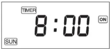
- Press the “▲MIN.” to change minutes (changes in 15 minute increments or “▼HOUR” to change hours to set the time for the program to start. The time flashes during setup.
- Press the "SET" button to confirm the time and go to the ON and OFF Settings.
NOTE: The time settings can only be set at 15 minutes after the previous programmed time or/and 15 minutes before the next programmed time.
For example, if the P01 program is set at 7:00 and P03 program is set at 16:00, the P02 programmed time can be set between 7:15 and 15:45. If the time selected beyond the range and press the "SET" button, an alarm will sound and then the time that can be set will be displayed.
Also, the same time cannot be set in the example above, so you cannot have 7:00 for P01 and 7:00 for P02 on Sunday.
ON and OFF Settings
- Press the “▲MIN.” or “▼HOUR” button to choose between ON or OFF.
The word "ON" or the word "OFF" will flash during the setting depending on which is selected. - Press the "SET" button to confirm and go to the Temperature Settings or Programming Selection step. See NOTES below:
NOTE: When "ON" is selected, the heater will operate at the temperature and the time selected. The screen will go to Temperature Settings step.
NOTE: When “OFF” is selected, the weekly timer does not work for that programming number. The screen will go to the same program number in the Program Selection step once you press “SET”.
Temperature Settings
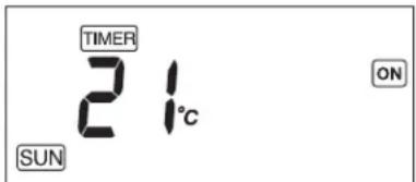
- Press the “▲MIN.” or “▼HOUR” button to select the desired temperature in that program. The temperature flashes during setup.
- Press the "SET" button to confirm the desired temperature and it will automatically go the same programming number in the Program selection.
2. Activate Weekly Timer Operation
If the “AUTO” button is pressed during operation (the heater is ON), the weekly programming will begin. The word “AUTO” will appear on the screen and the heater will operate according to the programming set in the Weekly Schedule.
If "ON" is displayed on the screen during the weekly schedule, the temperature can be changed by pressing the "▲MIN." or "▼HOUR" buttons. This will not change the temperature set in the Weekly Schedule. Also when the time gets to the next program number it will change automatically to the programmed temperature.
MANUAL COMBUSTION
IMPORTANT: This feature is for testing purpose only!
This heater also can be kept burning at desired combustion mode (High, Medium or low) manually, regardless of room temperature.
- Press the▲MIN." button and "▼HOUR" button at the same time for more than three (3) seconds when ON / OFF switch is "ON".
- P1, P2 or P3 will be displayed on the Digital indicator;
P1 = Low mode
P2 = Medium mode
P3 = High mode
Then select desired combustion mode by pressing “▲MIN.” or “▼HOUR” button. “▲MIN.” button changes combustion mode to higher, “▼HOUR” button changes combustion mode to lower.
- To clear, press the▲MIN." button and "▼HOUR" button at the same time for more than (3) seconds until normal temperature display returns.
AUTOMATIC CLEANING MODE
When the heater has been burning continuously for two hours at its highest setting, the burner will automatically start an auto clean procedure. The display will show the auto cleaning code [L:05 running back to [L:01]. The procedure takes 5 minutes to clean the burner automatically while the heater will burn at its lowest setting. After the cleaning mode is finished, the heater will automatically switch back to the highest setting again.
NOTE: Heater safety and start up procedures will still be operational in this mode.
If at any time a power failure occurs during operation, heater will turn off. When the power returns, the unit will automatically restart with the following conditions. Please reset each setting when the settings are erased as indicated below.
| TIME LENGTH OF POWER FAILURE | LESS THAN 3 SECONDS | MORE THAN 3 SECONDS | |
| IN BACKUP MEMORY OUT | OF BACKUP MEMORY | ||
| OPERATION Restart the combustion with the same condition before the power failure. | Start the combustion from the beginning. | Start the combustion from the beginning.Set temperature will change to 13^ ( 56^ ) for safety.Set temperature and room temperature will blank that at least more than 30 min. power failure has occurred.To stop the blinking the set temperature and room temperature, press any button once. | |
| POWER SAVER OPERATION | Keep the same condition before the power failure. | Keep the same condition before the power failure. | Keep the same condition before the power failure. |
| AUTO OPERATION | Keep the same condition before the power failure. | Keep the same condition before the power failure. | The setting will be erased.(See SECTION E: OPERATION) |
| CHILD LOCK OPERATION | Keep the same condition before the power failure. | The setting will be erased.(See SECTION E: OPERATION) | The setting will be erased.(See SECTION E: OPERATION) |
If at any time a power failure occurs when heater is not in operation, the unit will basically start the operation while keeping the same condition before the power failure. However, when the power failure continued more than 3 seconds, the following settings will be erased. Please reset each setting.
WHEN HEATER IS NOT IN OPERATION
| IN BACKUP MEMORY Child lock operation | |
| OUT OF BACKUP MEMORY | Clock and Day setting |
| Child lock operation | |
TURNING HEATER OFF
Press ON/OFF button to "OFF" position. ON lamp will flash and will go out. Circulation fan and blower motor continue to run for approx. three (3) minutes to cool down the heater.
SECTION F: ROUTINE MAINTENANCE
CAUTION: Be sure to turn off and unplug heater before performing any checks or cleaning. CAUTION: Allow heater to cool completely before cleaning or maintenance.
FOR OPTIMUM HEATER PERFORMANCE, THE PARTS SHOWN BELOW SHOULD BE CLEANED REGULARLY:
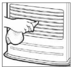
1. Clean Louvers (ONCE A WEEK)
Dust and stains should be wiped off louvers with a damp cloth.
natural_image
Illustration of a hand cleaning a textured surface with horizontal lines (no text or symbols)2. Clean Circulation Air Filter (ONCE A WEEK)
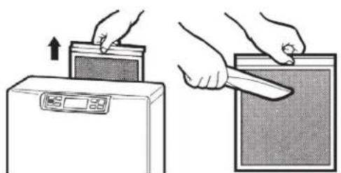
A mesh filter is located on heater cabinet rear side. Once a week slide the filter up to remove and it should be vacuumed clean.
natural_image
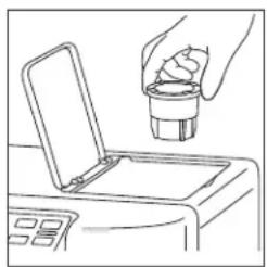
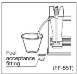
Illustration showing two hands using a digital kitchen appliance to press or install a rectangular device (no text or symbols present)3. Clean Fuel Acceptance Fitting (FF-55T)
When dirt or dust accumulates in the fuel acceptance fitting, it should be cleaned.
Check fuel acceptance fitting each time your refuel.
natural_image
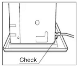
Line drawing of a hand pouring liquid into a container with an open lid (no text or symbols)4. Check for Fuel Leaks (REGULARLY)
FF-55T: Make it a habit to check for signs of fuel leakage. Wipe off any spilled fuel on the sub tank and removable fuel tank. Spilled fuel may cause odor or risk of fire.
FF-55: Make it a habit to check for any sign of fuel leakage along the fuel line and at all joints. Fuel leaks may lead to risk of fire.
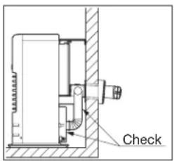
5. Check Flue Pipe Area (ONCE A MONTH)
Check the flue pipe joint to make sure connection is firm.
Use a vacuum cleaner to remove any dust or pet hair.
6. Clean Fuel Strainer (ONCE A MONTH) (FF-55)
The strainer of the fuel sump should be cleaned once a month and before starting the heater at the beginning of each season.
(a) Close the valve closest to the heater.
(b) To catch the fuel which will drain out, set the Oil catch below the strainer cover, with a small container under it.
(c) Loosen the two screws from the Strainer cover and remove.
(d) Remove the strainer and wash with fuel oil.
(e) Return the strainer to its original position. Replace strainer cover and screw to secure.
(f) Wipe away any spilled fuel.
(g) Open the valve in the fuel line. Check for fuel leakage.
NOTE: At the end of each season, unscrew the drain screw to remove all remaining fuel from the fuel sump.

7. Recommended Periodic Maintenance
As a state-of-the-art furnace, your heater requires periodic inspection and service by an authorized technician to insure optimum, trouble free performance. This inspection should include: a combustion check; flue pipe check; burner assembly check; cleaning all necessary parts and replacing gaskets as needed. Please ask your authorized TOYOTOMI dealer for details and scheduling.
AUTOMATIC IGNITER CLEANING SYSTEM
When the heater is on and clock is set (See SECTION E: OPERATION), it will automatically stop and clean the igniter every day at 2:00 and will display "CL" on the digital indicator. After the cleaning mode is finished the heater will automatically re-ignite and continue to burn again.
The igniter cleaning mode helps prolong the igniter life.
MANUAL IGNITER CLEANING SYSTEM
Heater will clean igniter for ten (10) minutes manually.
- When ON/OFF switch is "OFF", press the "TIMER" button and "POWER SAVER" button at the same time for more than three (3) seconds.
- Display will appear "CL:10" on Display. Cleaning will begin and end without any additional input. NOTE: Cleaning igniter is important to prolong igniter life. It is recommended that the igniter be cleaned once a month if the time is not set.
SECTION G: TROUBLESHOOTING
BEFORE REQUESTING A SERVICE CALL
The following symptoms are normal during operation of the heater.
| CONDITION REASON | ||
| When heater is started or extinguished. | White smoke or smell at initial use after purchase. | Machine oil or dust burns off the surfaces of the burner or heat exchanger. |
| Flames flashing for a few minutes after ignition. | The burner is cold and igniter is kept running for a while after ignition. | |
| Occasionally makes “cracking” noises when heater is ignited or extinguished. | Expansion and shrinkage of metal parts when they are heated or cooled. | |
| Warm air is not blow as soon as ignited. | To prevent uncomfortable cool air from coming out at the beginning, the circulation fan start up is delayed. | |
| Audible chugging sound from fuel pump when started first time or after running out of fuel. | Air is in the fuel pumpHowever, noise should stop within 1 minute.* | |
| When heater is in operation. | “Ticking” noise. Sound of fuel pump in normal operation. | |
| Heat chamber or heat exchanger can be seen through the air outlet louver’s glowing red hot. | Normal | |
| Occasional yellow flickering in blue flame. Normal | ||
| Odor | Spilled paraffinUse of inferior paraffin | - Wipe off any paraffin spills from fuel sub tank, removable fuel tank and drip tray.- Remove fuel and refuel using fresh, water-clear paraffin. |
*If sound from fuel pump does not decrease and heater shuts off, check: (FF-55)
- Push red float release button on the fuel sump once. DO NOT hold dawn.
- Insure that all valves are open and filter is clear.
- Insure external fuel tank has fuel and filters are clean.
Should problems arise during operation or ignition, use this chart to determine the cause and the proper steps to take. Be sure to unplug heater and allow to cool completely before taking corrective measures.
In the event that heater should extinguish itself, without any action or your part, you should look to the Display for any of the following error codes.
| ERROR CODE | CAUSE SOLUTION | |
| E-0 | Power failure (unstable frequency) | Check power source. |
| E-23 | Primary flame (Flame sensor) is malfunction and/or dirty | Consult your dealer for cleaning and in spection. |
| E-6 | Fuel line malfunction (FF-55) / Out of fuel | Consult your dealer. |
| E-2 | Out of fuel / no flame | Check fuel gauge; refuel. |
| E-2 / E-6 | Flue pipe blockage or leak | Consult your dealer. / Check flue pipe. |
| E-8 Blower motor malfunction Consult your dealer. | ||
| E-12 High | limit switch activated | Clean circulation fan filter and remove any obstructions, allow your heater to cool completely and re-ignite. |
| E-13 | Burner thermistor failure | Consult your dealer. |
| E-13 | Flue pipe blockage or leak | Check flue pipe. / Consult your dealer. |
| E-22 Ignition failure three times Consult your dealer. | ||
| FUEL | Out of fuel (FF-55T) | Refuel. (FF-55T) |
| Hi | Room temperature is higher than 35°C (95°F). Position of room temperature sensor is not correct. | Check the position of room temperature sensor. / Contact your dealer. |
| Lo | Room temperature is lower than -10°C (14°F). Room thermistor malfunction or disconnected. | Check the position of room temperature sensor. / Contact your dealer. |
SECTION H: LONG TERM STORAGE
At the close of each heating season, or when you do not plan to use your heater for an extended period, the following procedures are recommended.
-
As the end of the season approaches, calculate your fuel purchases so that you can use up all the fuel you have on hand. When fuel is stored for over six months, its quality may deteriorate. The use of such fuel will have an unfavorable effect on heater operation.
-
If your heater needs any service or repair, now is the time to call your dealer and get it done before storage. That way your heater will be ready for immediate use when the next heating season begins.
-
If you plan to store your heater in place,
(a) Disconnect power supply.
(b) FF-55T: Clean the fuel acceptance fitting and remove any paraffin, dust or water remaining in the fuel sub tank and removable fuel tank to prevent rusting.
FF-55: Close the main tank valve. Remove all fuel from the fuel sump and clean the fuel strainer. (See SECTION F: ROUTINE MAINTENANCE)
(c) Wipe off any stains or dust on heater with a damp cloth, then wipe once again using a dry cloth.


natural_image
Cartoon illustration of a smiling washing machine with sparkles and motion lines (no text or symbols)- To store heater in another location,
(a) Disconnect heater.
(b) FF-55T: Remove all fuel from the fuel sub tank and clean the fuel acceptance fitting.
FF-55: Close the main tank valve. Remove all fuel from the fuel sump and clean the fuel strainer. (See SECTION F: ROUTINE MAINTENANCE)
(c) FF-55T: Disconnect flue pipe from the heater.
FF-55: Disconnect fuel line and flue pipe from the heater.
NOTE: Fuel remaining in the fuel line may flow out when fuel line is disconnected. Have a container ready to catch drainage.
(d) Remove any soot accumulated in the flue pipe using a brush and/or vacuum cleaner.
(e) Wipe off any stains or dust on heater with a damp cloth, then wipe once again using a dry cloth.
(f) Put the heater in the original shipping box, and store in a dry place. If original shipping box is not available, cover the heater completely with a large plastic bag to protect from dust during storage.
(g) Plug exhaust and air intake openings of the flue pipe by using optional caps.
(Part #17212661 and #17212656)
TRANSPORTATION
Take the following measures to avoid fuel leakage during the transportation of the heater.
- ALWAYS move the heater in an upright position.
- ALWAYS drain fuel from the fuel sump before transportation. (FF-55)
SECTION I: INSTALLATION
GENERAL DESCRIPTION: The FF-55T/FF-55 is designed to be installed in an outside wall so the full advantage of installation simplicity can be made with the "Flue Pipe", which eliminates the need for tall chimney type flues. No hearth or fire surround is required.
STANDARD INSTALLATION PARTS
The following standard installation parts are enclosed with heater. For alternate installation methods, you may need to purchase additional accessories which are available from your TOYOTOMI dealer. (See ACCESSORY PARTS)
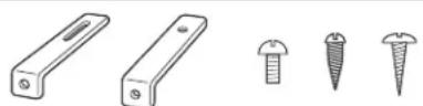
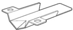
Wall Bracket (2 sets) (PART #17212589)
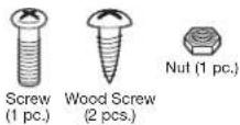
Tapping Screw (2) (PART #17208678)
Bind Tapping Screw (2) (PART #17187555)
Wood Screw (2) (PART #17206066)
(1) (PART #17206066)
(Room temperature sensor)
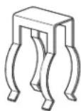
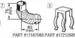
Pipe Holder (1) (PART #17212685)
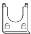
Pipe Stopper (1) (PART #17219378)

(3)
C
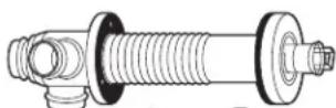
Flue Pipe (1) (PART #17224296)
Wood Screw (3) (PART #17206066)
Exhaust Air Cap (1) (PART #17212661)
Intake Air Cap (1) (PART #17212656)
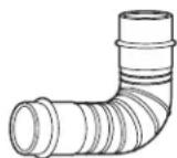
Bent Joint (L) (1)
(PART #17212798)
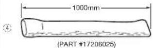
Insulating Cover (PART #17206025)
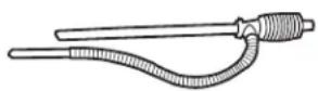
L-shaped Hose (2) (PART #17212692)
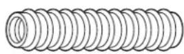
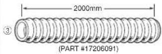
Inlet Hose (1) (PART #17206091) Hose Band
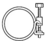
) (PART #17212677) (Hose Clamp)
(FF-55T)
Manual Fuel Pump (1) (PART #17027727)
(FF-55)
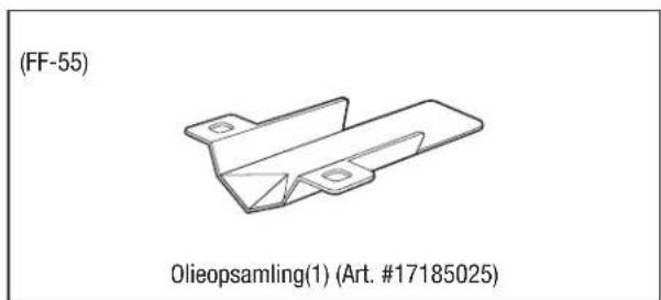
Oil Catch (1) (PART #17185025)
ACCESSORY PARTS
The following accessory parts are available for use in non-standard installation of the FF-55T/FF-55. After giving careful consideration to your desired heater and flue pipe locations and fueling system, consult your TOYOTOMI dealer to purchase the necessary accessory parts.
Important: Use only genuine TOYOTOMI parts for your heater. Use of unauthorized, generic or other brand parts can severely reduce performance and safety, and will void factory warranty.
Accessory Part No. Application
Extension pipe kit (L)* #17206013 Length: 2080 mm to 1620 mm
Extension pipe kit (M)* #17206012 Length: 1080 mm to 650 mm
Extension pipe kit (S)* #17206011 Length: 580 mm to 400 mm
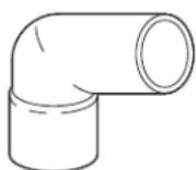
L-Shaped exhaust joint*
17187089
For 90 degree bend in exhaust pipe
*Total length of extension pipe between heater and flue pipe must be no greater than 3m. and no more than three bends may be used in extension pipe.
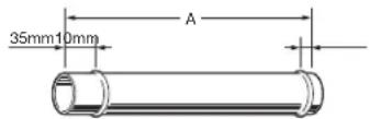
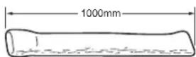
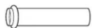
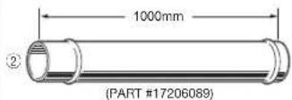
Exhaust extension pipe 1000 (PART #17206089) - Length (A) : 1000 mm
Exhaust extension pipe 500 (PART #17206083) - Length (A): 500 mm
Exhaust extension pipe 300 (PART #17206084) - Length (A): 300 mm
Exhaust extension pipe 200 (PART #17206087) - Length (A): 200 mm
Exhaust extension pipe 100 (PART #17206088) - Length (A): 100 mm
Exhaust extension pipe 75 (PART #17206098) - Length (A): 75 mm
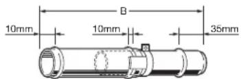
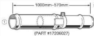
Adjustable exhaust pipe (L)
(PART #17206027) - Length (B) :
1000 mm\~570 mm
Adjustable exhaust pipe (S)
(PART #17206057) - Length (B):
500 mm\~320 mm
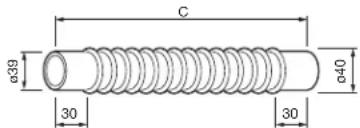
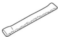
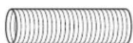
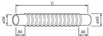
Flexible exhaust pipe 500
(PART #17206099) - Length (C):
500 mm
Flexible exhaust pipe 300
(PART #17206082) - Length (C):
300 mm
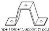
Pipe Support Hardware
PART #17206004
L-Shaped exhaust joint
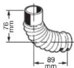
PART #17187089
Intake Hose
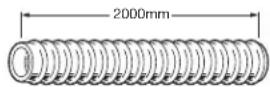
PART #17206091
Insulating cloth cover
PART #17206025
Intake Pipe Joint
PART #17206092
Extension Flue Pipe (S) (PART #17206051) - Wall thickness: 320 mm to 420 mm
Extension Flue Pipe (M) (PART #17206052) - Wall thickness: 420 mm to 520 mm
Extension Flue Pipe (L) (PART #17206053) - Wall thickness: 520 mm to 620 mm
EXTENSION KIT
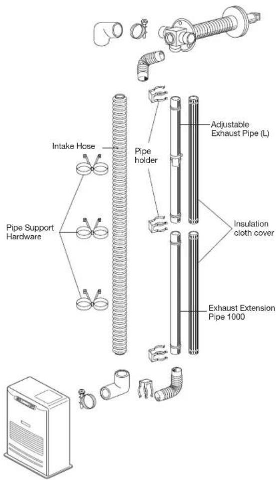
Extension Pipe Kit (L) PART #17206013

| No. | Name of Part Q'ty | |
| 1 | Adjustable Exhaust Pipe (L) 1000mm-570mm | 1 |
| 2 | Exhaust Extension Pipe 1000 (1000mm) | 1 |
| 3 | Intake Hose (2000mm) | 1 |
| 4 | Insulating cloth cover (1000mm) | 2 |
| 5 | Pipe Holder | 2 |
| 6 | Pipe Support Hardware | 3 sets |
| 7 | L-Shaped Exhaust Joint | 1 |
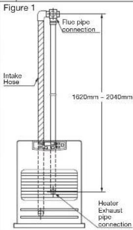
When using the "Extension pipe (L)" extension kit, the distance between the heater exhaust pipe connection and the flue pipe connection must be at least 1620 mm but no more than 2040 mm. (See Figure 1 for reference.)
INSTALLATION WITH EXTENSION PIPE KIT (L)
NOTE: Use "L"-shaped Exhaust Joint if necessary.
EXTENSION KIT
| Extension Pipe Kit (M) | PART #17206012 | ||
| 1 | 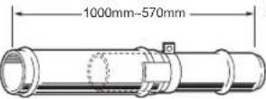 (PART #17206027) (PART #17206027) | 6 | 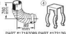 35 35 |
| 2 |  (PART #17206081) (PART #17206081) | 5 | PART #17206004Pipe Support HardwareXG4H)Pipe Holder Support (1 pc.) |
| 3 |  (PART #17206025) (PART #17206025) | 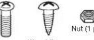 (pc.)Screw wood Screw(1 pc.) (2 pcs.) (pc.)Screw wood Screw(1 pc.) (2 pcs.) | |
| No. | Name of Part Q'ty | Figure 2 | |
| 1 | Adjustable Exhaust Pipe1000mm-570mm | 1 | |
| 2 | 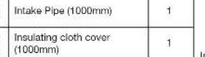 | 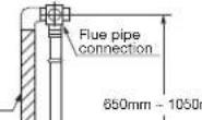 nm nm | |
| 3 | |||
| 4 | Pipe Holder | 1 | |
| 5 | 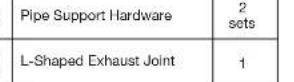 | ||
| 6 | |||
| When using the “Extension pipe (M)” extension kit, the distancebetween the heater exhaust pipe connection and the flue pipeconnection must be at least 650 mm but no more than 1080 mm.(See Figure 2 for reference.) | |||
| Extension Pipe Kit (S) PART #17206011 | |||
| 500mm-320mm(PART #17206057)500mm1000mm(PART #17206025) | 780mm89mmPART #17187069 PART #172126855PART #17206004Pipe Support HardwarePipe Holder (2 pcs.)Pipe Holder Support (1 pc.)Screw Wood Screw(1 pc.)Nut (1 pc.) | ||
| No. | Name of Part Q'ty | Figure 3 | |
| 1 | Adjustable Exhaust Pipe500mm-320mm | 1 | |
| 2 | Intake Pipe (500mm) | 1 | |
| 3 | Insulating cloth cover(1000mm) | 1 | |
| 4 | Pipe Holder | 1 | |
| 5 | Pipe Support Hardware | 1sets | |
| 6 | L-Shaped Exhaust Joint | 1 | |
| When using the “Extension pipe (S)” extension kit, the distancebetween the heater exhaust pipe connection and the flue pipeconnection must be at least 400 mm but no more than 575 mm.(See Figure 3 for reference.) | |||
When using the "Extension pipe (M)" extension kit, the distance between the heater exhaust pipe connection and the flue pipe connection must be at least 650mm but no more than 1080mm . The Figure 2 for reference.)
WiFi MODULE
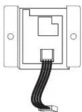
PART #17314780
INSTALLATION ADVICE
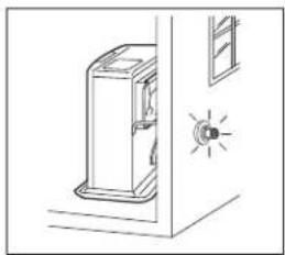
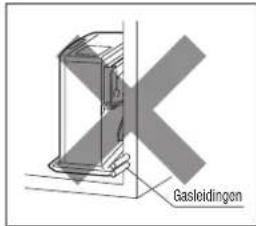
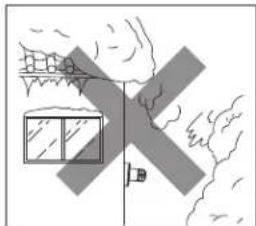
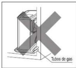
- Intake air and exhaust flue pipe openings of the Flue Pipe must be fully exposed to outside. The Flue Pipe must not vent into a chimney, garage, basement, under-floor or ceiling cavity, or any enclosed area, or be installed vertically, because the Flue Pipe is a "Heat Exchanger" which causes condensate to form in the exhaust pipe, and which must drain to outside.
- Install Flue Pipe Note the volume and temperature of the hot exhaust gas that the exhaust pipe discharges to outside, is minimal, and does not normally present any problems.
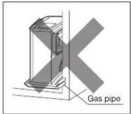
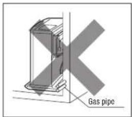
- Before making a hole in the wall for the Flue Pipe ensure the wall cavity is free of electrical wires, gas pipes and other obstacles. Drilling a 5 mm "pilot hole" from inside enables the final hole (and any associated "mess") to be completed from outside.
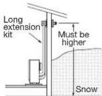
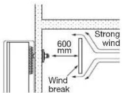
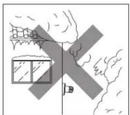
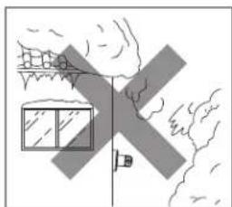
- DO NOT install Flue Pipe where the air supply or exhaust gas outlet might become covered by snowdrifts, fouled by outdoor debris, or directly exposed to winds over 50 kph.
IMPORTANT:
In areas of heavy snow falls, ground surface clearance must be increased according to average snow falls.
IMPORTANT:
In open area with strong wind, a wind break may be necessary.
natural_image
Simple line drawing of a door with a lit fuse and indicator light (no text or symbols)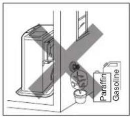
natural_image
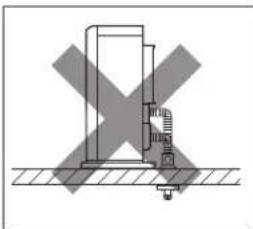
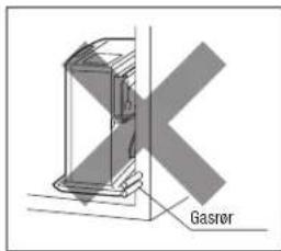
Simple line drawing of a house with windows and a flag, no text or symbols present- NEVER install the Flue Pipe below the heater.
natural_image
Diagram showing a mechanical or electrical component with a cross mark, no text or symbols present
natural_image
Diagram of a mechanical device with cross-shaped components and hatched background (no text or symbols)
natural_image
Isometric line drawing of a mechanical device with pulleys and a control panel (no text or symbols)- Total length of any Extension Pipe Kits (accessories L, M or S) between heater and Flue Pipe must not exceed 3 m, with not more than 3 × 90^ bends.
NOTE: When using Extension Pipe Kits type L, M or S always insulate hot exhaust pipe with the insulating cloth cover supplied. (More insulation may be required by Local Authority).
- For all heater installations, the Flue Pipe must always be installed. It must be horizontal with slight fall to outside … NEVER vertically.
INSTALLATION OF HEATER AND FLUE PIPE
A) Before commencing any installation work, check that the proposed installation will comply with Building Code requirements and Local Consent Authority rules that may apply to vented heaters in your area. (Check your Local Authority website, or consult your Installer / Supplier.)
B) The Flue Pipe is designed to be installed through the wall of any conventional building cladding, including Brick, Hebel, Linear, Gibraltar and Plaster Board, Tiles, Weatherboard, Plastered Polystyrene, and metal profiles etc.
C) The FF-55T / FF-55 heater is designed to be operated at altitudes up to 1,000 m, above sea level. For installation at altitudes between 1,000 m and 1,500 m, adjustments by authorized serviceperson is necessary. Consult your supplier for advice.
- Select heater location. Ensure minimum clearances as indicated below between heater and nearest combustible materials. Provide service access to clean the rear circulation air filter, fuel strainer (FF-55) and red float release button(FF-55).
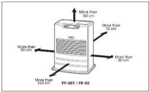
Fig. 1
- Ensure the outdoor flue discharge area is clear of anything that might be affected by the hot flue exhaust gas. (See Fig. 2 and 3.)
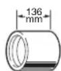
The Flue Pipe (as in Fig. 2), is for wall thickness from 130 mm to 320 mm.
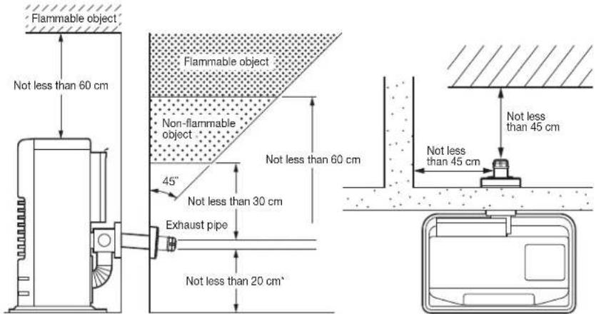
Fig. 2 Fig. 3
Flue Pipe Installation
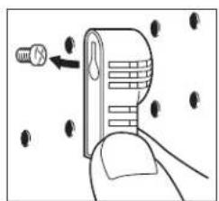
- A room temperature sensor is provided with approx. 2.5 m long extension wire. It is located on the rear of the cabinet. Make sure that the extension wire is not touching the exhaust pipe. The room temperature sensor can be installed with a wood screw. Screw down the wood screw provided with the heater into the desired location on the wall. Hook the back of the room temperature sensor.
NOTE: Choose a location for the sensor that is not in the path of direct sunlight, drafts or the flow of warm air from the heater.
natural_image
Illustration of a hand holding a device with arrows indicating movement or force (no text or symbols)Read installation manual before installing heater.
SECTION J: PRODUCT FICHE
| (a) Supplier's name/Trademark TOYOTOMI | |
| (b) Model FF-55T/FF-55 | |
| (c) EEC B | |
| (d) Direct heat output 5.5kW | |
| (e) Indirect heat output 6.0W | |
| (f) EEI 87.8% | |
| (g) Useful energy efficiency 92.4% | |
| (h) Specific precaution | For assembly, installation or maintenance instructions, please refer to the operating manual. |
WICHTIG
natural_image
Cartoon illustration of a smiling computer with a pencil and stars (no text or symbols)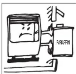
ABSCHNITT D:
natural_image
Illustration of a hand pressing a button with an upward arrow (no text or symbols)
natural_image
Line drawing of a hand holding a mechanical component (no text or symbols)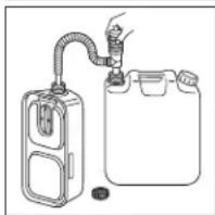
natural_image
Simple line drawing of a gas collection device with a hose and container (no text or symbols)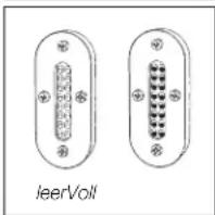
natural_image
Two identical oval-shaped electronic connectors with pins, labeled 'leerVolt' below (no additional text or symbols)
natural_image
Line drawing of a hand pressing a button on a mechanical component (no text or symbols)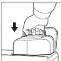
natural_image
Hand pressing a button on a mechanical component, with a downward arrow indicating compression (no text or symbols present)FF-55:
1) Ventil(e) öffnen
If using heater for the first time, press the red float release button in order to send fuel to the fuel sump and release.
“SUN P01” → “SUN P02” → “SUN P03” → “SUN P04” → “MON P01” → “MON P02” → ... → “SAT P04”
natural_image
Illustration of a hand cleaning a textured surface with horizontal lines (no text or symbols)natural_image
Illustration showing two hands installing or adjusting a door panel with a digital display (no text or symbols)natural_image
Line drawing of a hand pouring liquid into a container with an open lid (no text or symbols)natural_image
Cartoon illustration of a smiling washing machine with sparkles (no text or symbols)Adjustable exhaust pipe (L)
natural_image
Line drawing of a door with a lit fuse and window, no text or symbols present

natural_image
Simple line drawing of a house with windows and a vertical door, no text or symbols presentnatural_image
Diagram showing a mechanical or electrical component with a cross mark, no text or symbols present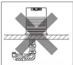
natural_image
Diagram of a mechanical or electrical component with cross-shaped hatching and layered structure (no text or symbols)
natural_image
Technical line drawing of a mechanical device with pulleys and a control panel (no text or symbols)natural_image
Illustration of a hand holding a device with a screw and arrow pointing to it, surrounded by scattered black dots (no text or symbols)natural_image
Cartoon illustration of a smiling refrigerator with a sparkle effect (no text or symbols)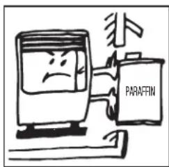
SECTION C: GUIDE DU COMBUSTIBLE
SECTION D:
COMMANDES DE FONC TIONNEMENT ET NOMS DES COMPOSANTS
natural_image
Illustration of a hand pressing a button on a device (no text or symbols visible)
natural_image
Line drawing of a hand holding a mechanical component (no text or symbols)
natural_image
Diagram of a gas collection or storage system with a coiled tube and container (no text or symbols)
natural_image
Two identical oval-shaped electronic connectors with pins, labeled 'leerVoll' below (no additional text or symbols)
natural_image
Line drawing of a hand turning a mechanical component (no text or symbols)
natural_image
Hand pressing a button on a device (no text or symbols visible)SPECIFICATIONS). On Display pre-set "Two Dashes" will be showing.
NOTE: Do not connect to an outlet shared with other appliances.
3. Régler l'horloge

FONCTIONNEMENT MANUEL
natural_image
Illustration of a hand cleaning a textured surface with a tool (no text or symbols)natural_image
Illustration showing two hands installing or adjusting a device with a digital display and a flat panel (no text or symbols)natural_image
Line drawing of a hand pouring liquid into a container with an open lid (no text or symbols)natural_image
Cartoon illustration of a smiling washing machine with a brush and sparkles (no text or symbols)RECOMMANDATIONS D'INSTALLATION
natural_image
Simple line drawing of a door with a lit fuse and indicator light (no text or symbols)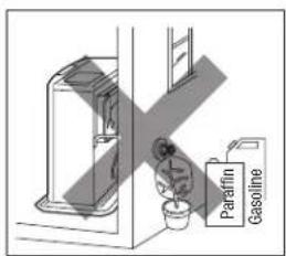

natural_image
Simple line drawing of a house with windows and a flag, no text or symbols presentnatural_image
Diagram showing a cross-shaped object with a vertical structure and base, no text or symbols present
natural_image
Diagram of a mechanical or electrical component with cross-shaped hatching and layered structure (no text or symbols)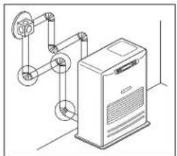
natural_image
Isometric line drawing of a mechanical device with pulleys and a control panel (no text or symbols)natural_image
Illustration of a hand holding a device with arrows indicating movement or force (no text or symbols)SECTION J: FICHE DU PRODUIT
natural_image
Cartoon illustration of a smiling computer with a pen and sparkle effect (no text or symbols)
HOOFDSTUK D:
BEDIENINGSELEMENTEN EN AANDUIDING VAN DE ONDERDELEN
natural_image
Hand pressing a button on a mechanical component (no text or symbols visible)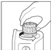
natural_image
Hand holding a mechanical component with a circular knob (no text or symbols visible)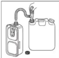
natural_image
Line drawing of a hand pressing down on a mechanical component (no text or symbols)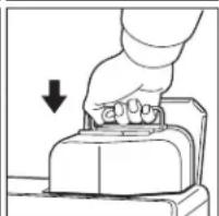
natural_image
Illustration of a hand pressing down on a mechanical component with a downward arrow (no text or symbols)FF-55:
“SUN” → “MON” → “TUE” → “WED” → “THU” → “FRI” → “SAT”
“SAT” → “FRI” → “THU” → “WED” → “TUE” → “MON” → “SUN”
“SUN P01” → “SUN P02” → “SUN P03” → “SUN P04” → “MON P01” → “MON P02” → ... → “SAT P04”
natural_image
Illustration of a hand cleaning a textured surface with horizontal lines (no text or symbols)natural_image
Illustration showing two hands operating a kitchen appliance: one with a hand inserting a component, the other holding a knife (no text or symbols present)natural_image
Line drawing of a hand pouring liquid into a container with an open lid (no text or symbols)4. Controle op brandstoflekken (RÉGULIÈREMENT)
natural_image
Cartoon illustration of a smiling washing machine with sparkles and motion lines (no text or symbols)natural_image
Line drawing of a door with a lit fuse and window, no text or symbols present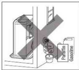
natural_image
Simple line drawing of a house with windows and a vertical line, no text or symbols presentnatural_image
Diagram showing a mechanical or electrical component with a cross symbol indicating a crossed-out section (no text or labels present)
natural_image
Diagram of a mechanical device with cross-shaped components and hatched background (no text or symbols)
natural_image
Technical line drawing of a mechanical device with pulleys and a control panel (no text or symbols)natural_image
Illustration of a hand holding a device with a screw and arrow pointing to it, surrounded by scattered black dots (no text or symbols)HOOFDSTUK J: PRODUCTFICHE
natural_image
Cartoon illustration of a smiling computer with a pen and sparkles (no text or symbols)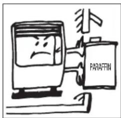
SECCIÓN D:
natural_image
Illustration of a hand pressing a button with an upward arrow (no text or symbols)
natural_image
Line drawing of a hand holding a mechanical component (no text or symbols)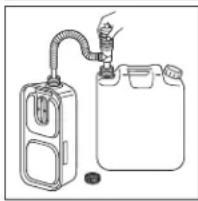
natural_image
Simple line drawing of a gas collection device with a hose and container (no text or symbols)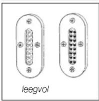
natural_image
Diagram of two electronic connectors labeled 'leegvol', showing pin layout without any text or symbols beyond the label.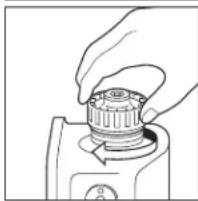
natural_image
Hand holding a mechanical component, possibly a pump or tool, with no visible text or symbols.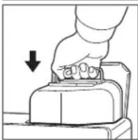
natural_image
Hand pressing a button on a device (no text or symbols visible)FF-55:
1) Abrir la(s) válvula (s)

“SUN” → “MON” → “TUE” → “WED” → “THU” → “FRI” → “SAT”
“SAT” → “FRI” → “THU” → “WED” → “TUE” → “MON” → “SUN”
natural_image
Illustration of a hand cleaning a textured surface with horizontal lines (no text or symbols)natural_image
Illustration showing two hands installing or adjusting a device with a digital display and a flat panel (no text or symbols)3. Limpiar Filtro de Combustible (FF-55T)
natural_image
Line drawing of a hand pouring liquid into a container with an open lid (no text or symbols)natural_image
Cartoon illustration of a smiling washing machine with sparkles (no text or symbols)Tubo de salida ajustable(L)
(PIEZA #17206027) - longitud (B) :
1000mm\~570mm
Tubo de salida ajustable (S)
(PIEZA #17206057) - longitud (B) :
500mm\~320mm
Tubo de escape flexible 500
(PIEZA #17206099) - longitud (C) :
500mm
Tubo de escape flexible 300
(PIEZA#17206082) - longitud (C) :
300mm
natural_image
Line drawing of a door with a lit fuse and window, no text or symbols present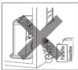
natural_image
Simple line drawing of a house with windows and trees, no text or symbols presentnatural_image
Diagram showing a cross-shaped object with a vertical structure and base, no text or symbols present
natural_image
Diagram of a mechanical or electrical component with cross-shaped hatching and layered structure (no text or symbols)
natural_image
Technical line drawing of a mechanical device with pulleys and a control panel (no text or symbols)natural_image
Illustration of a hand holding a device with arrows indicating movement or force (no text or symbols)natural_image
Cartoon illustration of a smiling refrigerator with a sparkle effect (no text or symbols)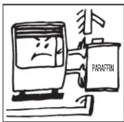
AFSNIT C: BRÆNDSTOFVEJLEDNING
AFSNIT D:
BETJENINGSKONTROLLER OG KOMPONENTNAVNE
natural_image
Illustration of a hand pressing down on a mechanical component with an upward arrow (no text or symbols)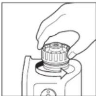
natural_image
Line drawing of a hand holding a mechanical component (no text or symbols)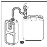
natural_image
Diagram of a gas collection or storage system with a coiled tube and container (no text or symbols)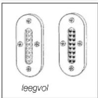
natural_image
Two identical oval-shaped electronic connectors with pins, labeled 'leegvol' below (no additional text or symbols)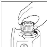
natural_image
Line drawing of a hand turning a mechanical component (no text or symbols)
natural_image
Hand pressing a button on a mechanical component, with a downward arrow indicating compression (no text or symbols present)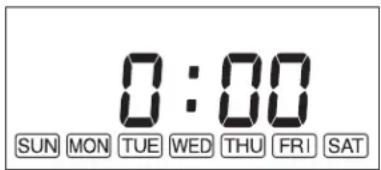
“SUN” → “MON” → “TUE” → “WED” → “THU” → “FRI” → “SAT”
“SAT” → “FRI” → “THU” → “WED” → “TUE” → “MON” → “SUN”
“SUN P01” → “SUN P02” → “SUN P03” → “SUN P04” → “MON P01” → “MON P02” → ... → “SAT P04”
natural_image
Illustration of a hand cleaning a textured surface with horizontal lines (no text or symbols)- Rengør cirkulationsluftfilter (EN GANG OM UGEN)
natural_image
Illustration showing two hands using a digital kitchen appliance to clean or store items (no text or symbols present)natural_image
Line drawing of a hand pouring liquid into a container with an open lid (no text or symbols)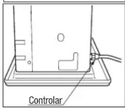
RENG∅RINGSSYSTEM TIL MANUEL TÆNDING
AFSNIT H: LANGTIDSOPBEVARING
natural_image
Cartoon illustration of a smiling washing machine with sparkles and motion lines (no text or symbols)- For at opbevare varmeapparatet et andet sted
(a) Skal du frakoble varmeapparatet.
natural_image
Simple line drawing of a ring clamp with a bolt, no text or symbols present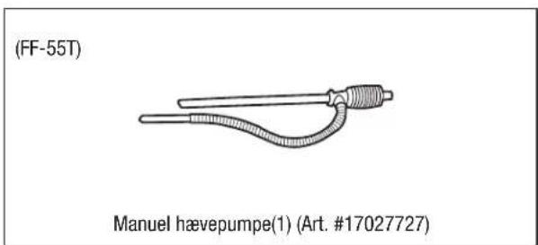
TILBEH∅RSDELE
INSTALLATIONSANBEFALING
natural_image
Line drawing of a door with a lit fuse and window, no text or symbols present

natural_image
Simple line drawing of a house with windows and a vertical line, no text or symbols present- Installer ALDRIG røgkanalen under varme-apparatet.

natural_image
Diagram showing a mechanical assembly with a cross symbol indicating a crossed part (no text or labels present)
natural_image
Diagram of a mechanical or electrical component with cross-shaped components and hatched background (no text or symbols)
natural_image
Technical line drawing of a mechanical device with pulleys and a control panel (no text or symbols)AFSNIT J:
TEKNISKE DATA

- For the Operate WiFi mode
- SECTION A: SPECIFICATIONS
- Flame Sensor
- Fuel Strainer (FF-55)
- Overheat Protector
- Power Failure Recovery System
- Fully Vented System
- SECTION B:
- SECTION C: FUEL GUIDE
- SECTION D:
- OPERATING CONTROLS AND PART NAMES
- BEFORE IGNITION
- Filling Fuel
- FF-55T:
- FF-55:
- Plug in the Heater
- Set Clock
- Setting of the Time and a Day of the Week.
- OPERATION
- MANUAL OPERATION
- Turning Heater ON
- Adjusting Room Temperature
- FUEL INDICATOR LIGHT (FF-55T)
- Weekly Schedule setting
- Program Selection
- Program Time Settings
- ON and OFF Settings
- Temperature Settings
- Activate Weekly Timer Operation
- MANUAL COMBUSTION
- AUTOMATIC CLEANING MODE
- TURNING HEATER OFF
- SECTION F: ROUTINE MAINTENANCE
- Clean Louvers (ONCE A WEEK)
- Clean Circulation Air Filter (ONCE A WEEK)
- Clean Fuel Acceptance Fitting (FF-55T)
- Check for Fuel Leaks (REGULARLY)
- Check Flue Pipe Area (ONCE A MONTH)
- Clean Fuel Strainer (ONCE A MONTH) (FF-55)
- Recommended Periodic Maintenance
- AUTOMATIC IGNITER CLEANING SYSTEM
- MANUAL IGNITER CLEANING SYSTEM
- SECTION G: TROUBLESHOOTING
- SECTION H: LONG TERM STORAGE
- TRANSPORTATION
- SECTION I: INSTALLATION
- STANDARD INSTALLATION PARTS
- ACCESSORY PARTS
- Accessory Part No. Application
- 17187089
- EXTENSION KIT
- Extension Pipe Kit (L) PART #17206013
- INSTALLATION WITH EXTENSION PIPE KIT (L)
- WiFi MODULE
- INSTALLATION ADVICE
- INSTALLATION OF HEATER AND FLUE PIPE
- SECTION J: PRODUCT FICHE
- WICHTIG
- ABSCHNITT D:
- SECTION C: GUIDE DU COMBUSTIBLE
- COMMANDES DE FONC TIONNEMENT ET NOMS DES COMPOSANTS
- Régler l'horloge
- FONCTIONNEMENT MANUEL
- RECOMMANDATIONS D'INSTALLATION
- SECTION J: FICHE DU PRODUIT
- HOOFDSTUK D:
- BEDIENINGSELEMENTEN EN AANDUIDING VAN DE ONDERDELEN
- Controle op brandstoflekken (RÉGULIÈREMENT)
- HOOFDSTUK J: PRODUCTFICHE
- SECCIÓN D:
- Limpiar Filtro de Combustible (FF-55T)
- AFSNIT C: BRÆNDSTOFVEJLEDNING
- AFSNIT D:
- BETJENINGSKONTROLLER OG KOMPONENTNAVNE
- RENG∅RINGSSYSTEM TIL MANUEL TÆNDING
- AFSNIT H: LANGTIDSOPBEVARING
- TILBEH∅RSDELE
- INSTALLATIONSANBEFALING
- AFSNIT J:
- TEKNISKE DATA
Brand : Toyotomi
Model : FF55T
Category : Heating