
ACOM2 - Processor ALTO - Free user manual and instructions
Find the device manual for free ACOM2 ALTO in PDF.
| Product Type | Stereo Compressor/Limiter/Noise Gate |
| Brand | Alto Professional |
| Model | ACOM2 |
| Number of Channels | 2 independent channels or stereo coupling |
| Input Connectors | Balanced XLR and 1/4" (6.35 mm) TRS |
| Output Connectors | Balanced XLR and 1/4" (6.35 mm) TRS |
| Sidechain | Send and Return on unbalanced 1/4" (6.35 mm) jack |
| Power Supply | Mains via included power cable |
| Rack Mount | Standard 19" (1U), depth with cabling: additional 4" |
| Compressor Threshold Range | -40 dBu to +20 dBu |
| Expander Threshold Range | Adjustable, disable by turning fully counterclockwise |
| Compression Ratio | From 1:1 to ∞:1 (limiter) |
| Attack Time | 1 ms to 200 ms (manual), automatic via Auto switch |
| Release Time | 0.05 ms to 4 s (manual), automatic via Auto switch |
| Sidechain Low-Pass Filter | Switchable, to reduce kick drum oscillations |
| VU Meters | 12 LEDs for gain reduction, input/output switchable |
| Special Features | SKC mode (Smart Knee Control), peak limiter, ducking |
| Maintenance | Clean with a dry cloth. Avoid moisture and shocks. |
| Safety | Follow hearing protection guidelines. Orderly power on/off. |
Frequently Asked Questions - ACOM2 ALTO
User questions about ACOM2 ALTO
0 question about this device. Answer the ones you know or ask your own.
Ask a new question about this device
Download the instructions for your Processor in PDF format for free! Find your manual ACOM2 - ALTO and take your electronic device back in hand. On this page are published all the documents necessary for the use of your device. ACOM2 by ALTO.
USER MANUAL ACOM2 ALTO
ACOM2
USER GUIDE
ENGLISH (2 - 10)
GUÍA DEL USUARIO
ESPAÑOL (11 - 20)
GUIDE D'UTILISATION
FRANÇAIS (21 - 30)
GUIDA PER L'USO
ITALIANO (31 - 39)
BENUTZERHANDBUCH
DEUTSCH (40 - 48)
GEBRUIKERSHANDLEIDING
NEDERLANDS (49 - 57)
USER GUIDE (ENGLISH)
BOX CONTENTS
- ACOM2
- Power Cable
- User Guide
• Safety Instructions & Warranty Information Booklet
- Make sure all items listed in the Box Contents are included in the box.
-
READ SAFETY INSTRUCTION BOOKLET BEFORE USING THE PRODUCT.
-
Switch everything on in the following order:
• audio input sources (i.e. instruments, CD/MP3 players)
- ACOM2
- speakers/amps
-
When powering down, switch everything off in the following order:
-
speakers/amps
- ACOM2
- last, any input sources
CAUTION! Permanent hearing loss may be caused by exposure to extremely high noise levels. The U.S. Government's Occupational Safety and Health Administration (OSHA) has specified permissible exposures to certain noise levels.
According to OSHA, exposure to high sound pressure levels (SPL) in excess of these limits may result in hearing loss. When using equipment capable of generating high SPL, use hearing protection while such equipment is under operation.
| HOURS PER DAY SPL | EXAMPLE | |
| 8 | 90 | Small |
| 6 | 92 | Train |
| 4 | 95 | Subway |
| 3 97 High level desktop | monitors | |
| 2 100 Classical music concert | ||
| 1.5 | 102 | Riveting |
| 1 | 105 | Machine |
| .50 | 110 | Airport |
| .25 or less 115 Rock concert |
INTRODUCTION
Thanks for purchasing the Alto Professional ACOM2 Compressor/Limiter/Gate! ACOM2 is a powerful dynamic processor with several innovative circuit designs that make it a versatile product: smart and fast recognition of the source material, adjustable Expander/Gate, and a low distortion Voltage Control Amplifier (VCA).
- Two independent, full-featured compressor/limiters in one compact rack
• Use as two individual mono processors, or stereo-link to provide true stereo compression
• Auto-attack/-release switch automatically adjusts compression to source signal
• Full manual mode for tailored adjustment to any venue - Minimized signal path with high-quality VCA: low noise, minimal distortion and optimal temperature stability
• Intelligent Knee for musical performance with soft and hard-knee envelopes - Couple switch for a one-touch selection between two mono channels or stereo-linked operation
- Sidechain send and return for use in an external effects loop
- Switchable low-cut filter minimizes audio-program pumping triggered by kick drum
• Gain-reduction LEDs and switchable input/output-level LED meters for visual monitoring of critical values
• Bypass switches on both channels
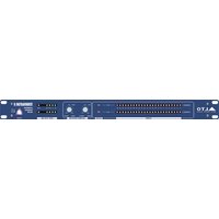
FRONT PANEL CONTROLS
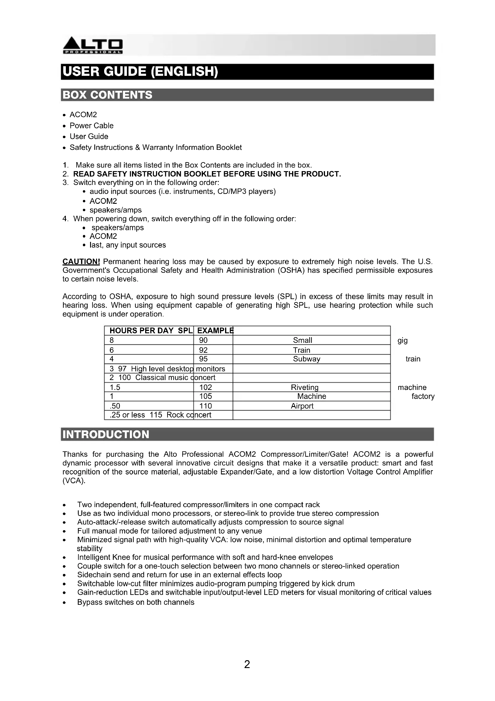
Couple Switch
- Dual mono – When activated, this links two mono channels together.
- Ch 1 master - When the Couple Switch is engaged, Channel 1 will take control of both channels and override all the controls and switches of Channel 2 with the exception of the SC Monitor, SC External, SC Filter, Bypass and Peak Limiter control.
Expander/Gate
- Threshold control - Adjusts the threshold level for the Expander/Gate section.
- Ratio control - Determines the expansion ratio when the signal drops below the threshold level.
- Threshold LED - The "+" LED lights up when the audio signal goes below the set Threshold. The "-" LED lights up when being used as an expander.

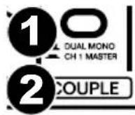
Compressor
- Threshold control - Adjusts the threshold level for the Compressor section in the range of -40 dBu to +20 dBu. Signals that go above the set threshold will be compressed.
- Threshold LED - Shows the state of the input signal in relation to the threshold level. If the input signal falls below the set threshold level the left "-" LED will light up and the signal will not be compressed. If the input signal rises above the set threshold level, this signal will be compressed and the SKC (Smart Knee Control) level will be shown by the middle "0" LED.
- Ratio control - The ratio between the input and output level of audio signals exceeding the set threshold.
- Attack control - Determines how fast the compressor reacts to audio signals that exceed the set threshold.
- Release control - Determines how fast the compressor returns to unity gain when the audio signal falls below the threshold level.
- Auto switch - Allows the attack and release controls to be automatically set based on the audio signal.
- Output gain control - Adjusts the output signal by a maximum of 20 dB to recover the level lost during compression.
- SC External switch - Separates the connection between the audio input and the sidechain path but allows an external signal through the sidechain return jack.
- SC Monitor Switch - Connects the sidechain control signal to the audio output, muting the audio input and monitoring the sidechain signal being returned via external signal processors.
- SC Filter switch - Activates a low-cut filter in the sidechain path, eliminating unwanted noise generated by low frequencies.
- Smart switch - Hard knee mode will be converted into SKC (Smart Knee Control) mode for musically transparent compression.
- Bypass switch - Turns off the corresponding channel to make an A/B comparison of the processed and unprocessed signal.
- Input/output meter switch - Switches to the input level meter when turned on; switches to the output level meter when turned off.
- Input/output level meter - Displays the input or output level.
- Gain reduction meter - Displays the amount of gain reduction.
Limiter
- Threshold control - Controls the level of the Limiter.
- Limiter LED - Lights up when the Limiter function is activated.

REAR PANEL CONTROLS

- Power connector - Connect the included power cable here.
- Audio in - Balanced 1/4" TRS jack and XLR input connectors.
- Audio out - Balanced 1/4" TRS jack and XLR output connectors.
- Operating level control - Sets the operating level to either -10 dBV or +4 dBu.
- Sidechain send - 1/4" unbalanced jack to route audio to an external processor.
- Sidechain return - 1/4" jack processes the return signal sent from an external processor.
COMPRESSOR CONCEPTS
Digital audio equipment usually has a very high dynamic range: up to 125 dB. However, the dynamic range of analog equipment is about 25 dB less. Using tapes and vinyl records further reduces the dynamic range.
SIGNAL-TO-NOISE RATIO
All electronic equipment produces some noise when current flows through its conductor. The noise is further amplified when it occurs across the whole spectrum of audio. Even "low-noise" components still have some residual noise. For example, most tape recorders have a signal-to-noise ratio (SNR) of 70 dB or less, a level that most of today's listeners would recognize as low-quality.
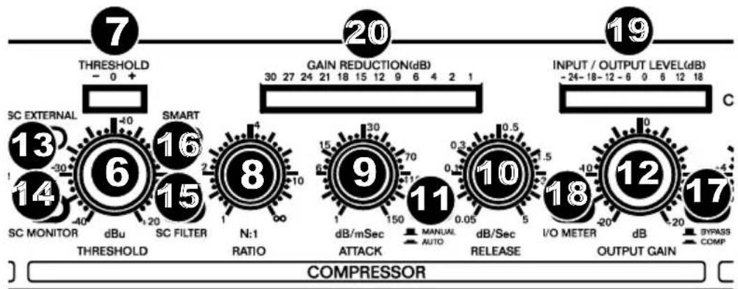
DYNAMICS
The chart below shows the dynamic ranges of various devices compared to the human ear.
bar
| Category | Power (dB) | | :--- | :--- | | Ear Pream | 150 | | Microphone p | 130 | | Power Amplifier | 110 | | Tape Recorder | 85 | | Radio Recorder | 65 | | Cassette | 55 |The range of these devices is actually further reduced when accounting for 10-20 dB of "headroom" to avoid distortion from the source audio, which has its own dynamic range. The device's operating level must be as high as possible but not high enough to generate distortion. We recommend using ACOM2's AGC (automatic gain control), which monitors the signal in real time and adjusts the gain to an optimal SNR without producing distortion.
COMPRESSORS AND LIMITERS
To prevent an audio signal from "clipping" or distorting at high levels, ACOM2 uses a compressor/limiter. Both do the same job, but a limiter reduces the audio signal above a set threshold, while a compressor reduces the signal in a much more complex way and over a wide range of levels. A compressor reduces the signal based on various parameters you set (attack, release, ratio, knee, etc.).
EXPANDER/GATE SECTION
Microphones, amplifiers, guitar pickups, etc. generate some noise that will reduce your signal quality, either at low frequencies (hum) or at high frequencies (hiss). The signal itself often "masks" this noise, but it's more noticeable during quiet parts or silence, when the signal is closer to the noise floor. To prevent this, ACOM2 uses an expander and noise gate.
An expander is the opposite of a compressor: it attenuates (reduces) the signal when the amplitude drops below a set threshold. The expander automatically reduces the level of the audio signal below a set threshold, using a flat ratio curve. ACOM2 is equipped with a new kind of expander, the SRC (Smart Ratio Control). The ratio of the SRC is automatically adjusted according to the audio signal level. While conventional expanders can often make overly "conspicuous" gain changes, the SRC has a non-linear ratio curve, which is softer and user-adjustable. Quiet sounds close to the noise floor level will be processed with a minimum ratio of expansion while higher-level signals will be processed with a higher ratio, resulting in greater attenuation.
A noise gate is like a simpler version of the expander. While the expander continuously attenuates the signal below the set threshold, a noise gate simply silences the signal completely below a set threshold.
Threshold Adjustment
The threshold control covers a wide range and is efficient with any working level. To turn off the Expander/Gate completely, turn the threshold control fully counterclockwise.

line
| Input | Output | |-------|--------| | SRC Curve | Low | | Conventional Expander Curve | High | | Threshold | Medium |Compressor Threshold Control
The compressor threshold control sets the point where the input level starts to be reduced. For instance, if the level is +12 dBu and the threshold control is set to +2 dBu, then up to 10 dB can be compressed. If the input level is +12 dBu and the control is set to -10 dBu, then the maximum compression will be 22 dB.
The threshold control's operating range is -40 dBu to +20 dBu. Remember that the degree and the type of compression depend not only on the threshold control but also on other controls, like Ratio, Attack, and Release.
Ratio Control
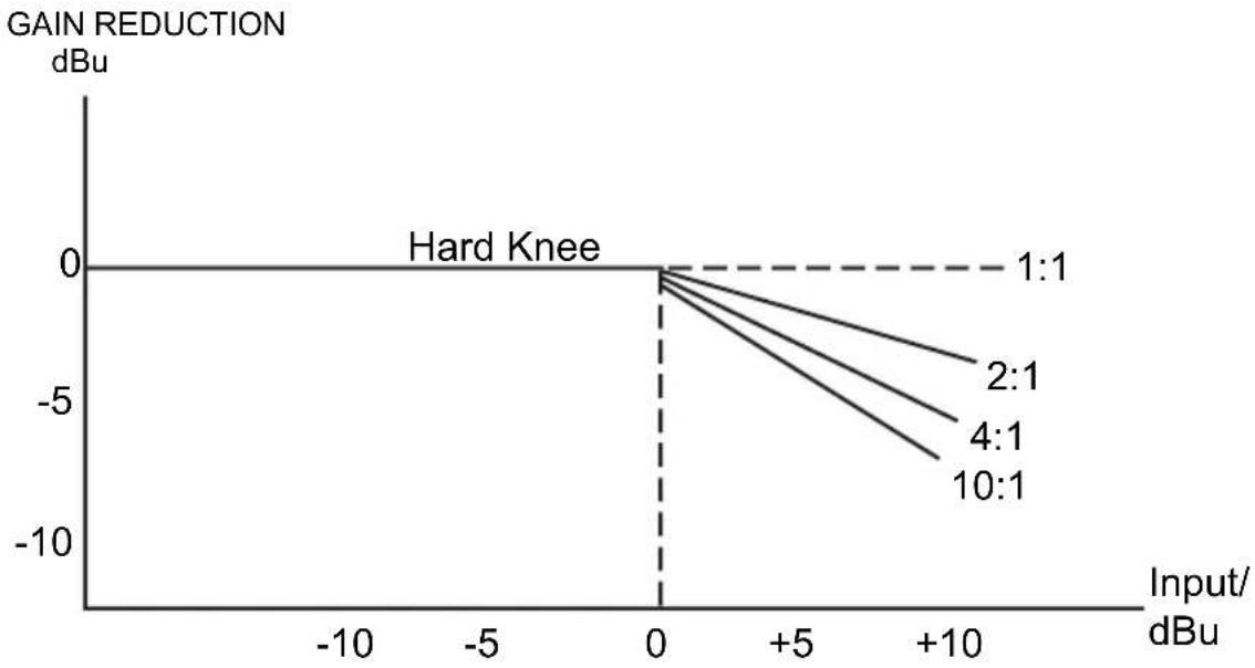
This control sets the ratio of input level to output level but only for the signals that exceed the threshold. The scale of the ratio control on the front panel (calibrated in dB) indicates how much input level is required to decrease the output level by 1 dB. If you have a ratio equal to 1:1 you will get the same level of input and output signal: no level change.
If you have a ratio of 2:1 this means that for every 2 dB increase of the input level (above the threshold) you will get an increase of output level of only 1 dB. Similarly, a ratio of 10:1 means that every 10 dB increase of the input level above the threshold results in an output level increase of only 1 dB. Essentially, the greater the ratio, the more compression is applied to the signal above the threshold. Higher ratio settings produce less natural sounds, so use a ratio of 4:1 or lower if you want only a subtle effect on the dynamic range of a source.

line
| Input | Output | Gain 0 dB | Ratio 2:1 | Ratio 4:1 | Limiter∞:1 | |-------|--------|-----------|-----------|-----------|------------| | Low | Low | - | - | - | - | | Mid | Mid | - | - | - | - | | High | High | + | - | - | - |Attack control
The attack control represents the amount of time it takes before the compressor starts to lower the output level when the signal is above the threshold point.
We recommend using a short attack time for very fast transients, such as drums, handclaps, etc. These peaks are carefully regulated by the compressor. When setting the attack control, start with longer attack times and gradually reduce it until you reach an optimal setting. The minimum attack control time is 1 millisecond; the maximum is 200 milliseconds.
Release control
The release control determines how much time the compressor needs to return to normal gain when the audio signal falls below the set threshold. A release time that is too short will make the volume fluctuate, resulting in a "pumping" effect. A release time that is too long will produce a "pumping" and breathing effect, especially when you have a loud passage followed by a quiet passage. The minimum release time is .05 milliseconds; the maximum is 4 seconds.
Auto switch
This switch activates an intelligent program recognition circuit, which automatically sets the optimal attack and release times while also avoiding distortion and pumping effects. When activated, this switch disables the manual attack time and release time settings.
Output control
This control compensates for the loss of level generated by the gain reduction caused by compression and limiting.
Effect switch
This switch turns off the corresponding channel, which is useful for comparing the processed and unprocessed signal.
Gain Reduction Meter
This 12-LED meter on the front panel indicates the amount of gain reduction in real time.
line
| Input/dBu | Gain Reduction (dBu) for 1:1 | Gain Reduction (dBu) for 2:1 | Gain Reduction (dBu) for 4:1 | Gain Reduction (dBu) for 10:1 | | --------- | ---------------------------- | ---------------------------- | ---------------------------- | ----------------------------- | | 0 | 0 | 0 | 0 | 0 | | +5 | -5 | -6 | -7 | -8 | | +10 | -10 | -11 | -12 | -13 |Limiter Section
The attack time determines how fast the compressor reacts to a signal above the threshold. To avoid "clipping" the signal, we recommend using a longer attack time for low frequencies and a shorter attack time for high frequencies. When mixing a source with a wide range of frequencies, choose a setting that will benefit the lower frequencies.
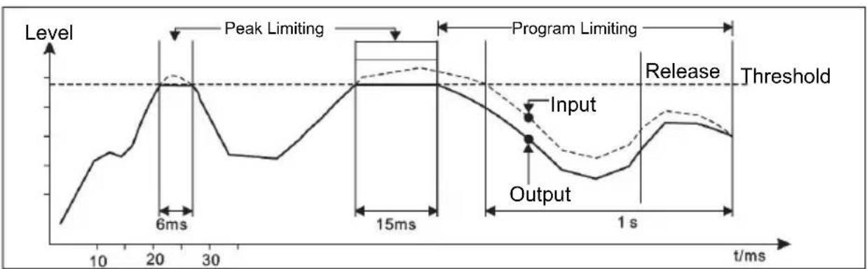
The chart below illustrates how the Smart Gain Control (SGC) limiter works. The curve in bold is the output signal and the dashed curve above it is the input signal. The area between the two is the amount of gain reduction. The limiter will turn on when the signal exceeds the threshold for more than 15 microseconds. One second after the signal is below the threshold again, gain reduction will return to 0 dB and, in this case, input and output signals will be identical again.
line
| Time (ms) | Level | | --------- | ----- | | 0 | Low | | 10 | Medium| | 20 | Peak Limiting | | 30 | Low | | 15 | High | | 1 s | Low | | >1 s | High |APPLICATIONS
ACOM2 can be used in a variety of situations:
Compressor - If an audio signal exceeds the set threshold, the signal will be reduced in gain proportional to how much it exceeds the threshold.
Ducking - Ducking automatically reduces the volume of background music whenever an external source is detected (e.g., when an announcer begins to speak). To use the compressor as a ducker, plug the announcer's mic into a mixer and route that mic signal to the compressor's Sidechain Return. Plug the music source into ACOM2's inputs. Set the compressor controls like this:
• Threshold: +3 dB
• Ratio: 6:1
- Attack: \~1 ms
- Release: \~1 sec.
- Turn on the Smart switch for SKC Mode
When the announcer speaks, the music will be "ducked." Increase the ratio to duck it even lower. When the announcer finishes speaking, the music will fade back in at the rate set by the Release knob.
Limiter - Set ACOM2 with a high ratio and a high threshold. Softer sections will remain uncompressed, while louder peaks will be kept under control. Set the Threshold so that the loudest sections get around -6 dB of reduction, set the Ratio for 6:1, and turn on the Smart switch for SKC mode.
Noise gate - ACOM2's compressor can be used as a noise gate to block unwanted signal (hiss and noise) below a set threshold, so only the intended instrument signal is heard. When the instrument's signal stops, dropping beneath the threshold, the gate will activate, and the noise that you'd normally hear will be muted.
De-Essing - When recording vocals, high frequency "s" sounds can jump out louder than the rest of the audio. By placing an equalizer (like the AEQ231) in the sidechain, you can set the compressor so that only certain frequency ranges trigger ACOM2's compressor. Set the EQ to cut all frequencies except for the sibilant range, between 3-6 kHz. Then, set ACOM2 like this:
- Threshold: \~0 dB
• Ratio: 6:1 - Attack: 1 ms
- Release: \~0.1 ms
Expander - An expander is a compressor in reverse. It increases the dynamic range of the audio signal, making quiet sounds even quieter by reducing the level of a signal below a set threshold level. Signals above the threshold remain at unity gain, and signals below the threshold are reduced in gain.
RACK MOUNTING
For secure mounting, you can mount ACOM2 into a standard 19" rack space unit (available from various rack manufacturers or your music dealer). Allow at least an additional 4" depth for cabling on the rear panel. Be sure that there is enough air space around the unit for sufficient ventilation, and do not place ACOM2 on high-temperature devices (e.g., power amplifiers) to avoid overheating.
INSTALLATION AND CONNECTION
Read this section carefully. Not paying enough attention to the input signal's level, routing, or assignment of can result in unwanted distortion, a corrupted signal or no sound at all.
Audio Connection
ACOM2's compressor/limiter/gate is equipped with balanced XLR connectors. It can be connected to other units in a variety of ways to support a vast range of applications without experiencing a signal loss.
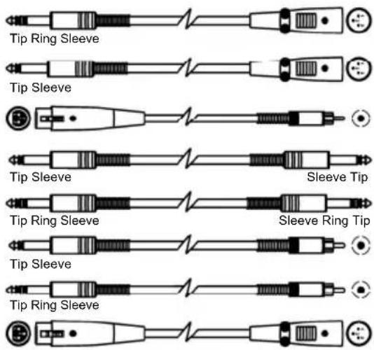
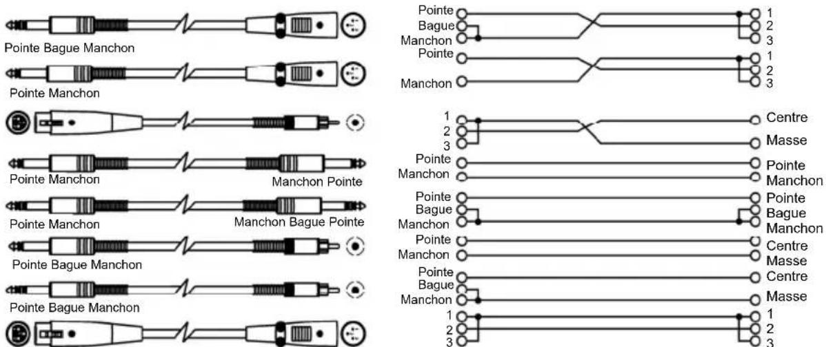
Wiring Configuration
ACOM2 has both balanced and unbalanced connections, ensuring compatibility with other common audio processors and mixers.
Please see following drawings for details:
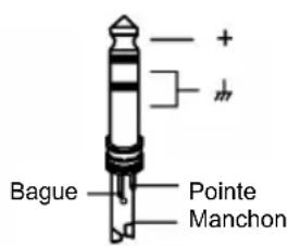
- For 1/4" Phone jack

TS Type Unbalanced
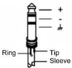
TRS Type Balanced
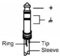
TRS Type Unbalanced
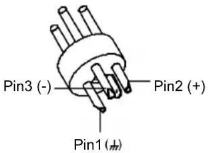
- For XLR connector
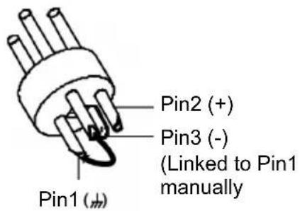
XLR Type Unbalanced XLR Type Balanced
In Line Connection
- Balanced
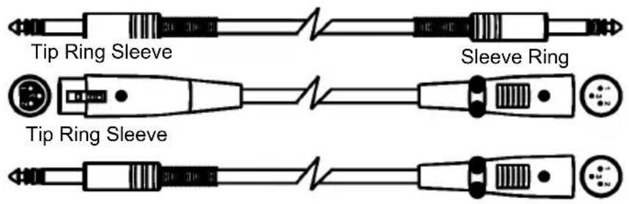

- Unbalanced

flowchart
graph TD
    A["Tip"] --> B["1"]
    C["Ring"] --> D["2"]
    E["Sleeve"] --> F["3"]
    G["Tip"] --> H["1"]
    I["Sleeve"] --> J["2"]
    K["Tip"] --> L["3"]
    M["Ring"] --> N["2"]
    O["Sleeve"] --> P["3"]
    Q["Tip"] --> R["1"]
    S["Sleeve"] --> T["2"]
    U["Tip"] --> V["3"]
    W["Ring"] --> X["2"]
    Y["Sleeve"] --> Z["3"]
    AA["Tip"] --> AB["1"]
    AC["Sleeve"] --> AD["2"]
    AE["Tip"] --> AF["3"]
    AG["Ring"] --> AH["2"]
    AI["Sleeve"] --> AJ["3"]
    AK["Tip"] --> AL["1"]
    AM["Sleeve"] --> AN["2"]
    AO["Tip"] --> AP["3"]
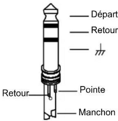
Insert Points Connection
- 1/4" TRS insert
- Insert Leads


flowchart
graph TD
    A["Tip"] --> B["Ring"]
    A --> C["Sleeve"]
    D["Tip"] --> E["Ring"]
    D --> F["Sleeve"]
    G["Tip"] --> H["Ring"]
    G --> I["Sleeve"]
    J["Tip"] --> K["Ring"]
    J --> L["Sleeve"]
    M["Tip"] --> N["Ring"]
    M --> O["Sleeve"]
    P["Tip"] --> Q["Ring"]
    P --> R["Sleeve"]
    S["Tip"] --> T["Ring"]
    S --> U["Sleeve"]
    V["Tip"] --> W["Ring"]
    V --> X["Sleeve"]
    Y["Tip"] --> Z["Ring"]
    Y --> AA["Sleeve"]
    AB["Tip"] --> AC["Ring"]
    AB --> AD["Sleeve"]
    AE["Tip"] --> AF["Ring"]
    AE --> AG["Sleeve"]
    AH["Tip"] --> AI["Ring"]
    AH --> AJ["Sleeve"]
    AK["Tip"] --> AL["Ring"]
    AK --> AM["Sleeve"]
    AN["Tip"] --> AO["Ring"]
    AN --> AP["Sleeve"]
    AQ["Tip"] --> AR["Ring"]
    AQ --> AS["Sleeve"]
    AT["Tip"] --> AU["Ring"]
    AT --> AV["Sleeve"]
    AW["Tip"] --> AX["Ring"]
    AW --> AY["Sleeve"]
    AZ["Tip"] --> BA["Ring"]
    AZ --> BB["Sleeve"]
    BC["Tip"] --> BD["Ring"]
    BC --> BE["Sleeve"]
    BF["Tip"] --> BG["Ring"]
    BF --> BH["Sleeve"]
    BI["Tip"] --> BJ["Ring"]
    BI --> BK["Sleeve"]
    BL["Tip"] --> BM["Ring"]
    BL --> BN["Sleeve"]
    BO["Tip"] --> BP["Ring"]
    BO --> BQ["Sleeve"]
    BR["Tip"] --> BS["Ring"]
    BR --> BT["Sleeve"]
    BU["Tip"] --> BV["Ring"]
    BU --> BW["Sleeve"]
    BX["Tip"] --> BY["Ring"]
    BX --> BZ["Sleeve"]
    CA["Tip"] --> CB["Ring"]
    CA --> CC["Sleeve"]
    CD["Tip"] --> CE["Ring"]
    CD --> CF["Sleeve"]
    CG["Tip"] --> CH["Ring"]
    CG --> CI["Sleeve"]
    CJ["Tip"] --> CK["Ring"]
    CJ --> CR["Sleeve"]
    CS["Tip"] --> CT["Ring"]
    CS --> CU["Sleeve"]
    CV["Tip"] --> CW["Ring"]
    CV --> CX["Sleeve"]
    CY["Tip"] --> CZ["Ring"]
    CY --> DA["Sleeve"]
    DB["Tip"] --> DC["Ring"]
    DB --> DD["Sleeve"]
    DP["Tip"] --> DJ["Ring"]
    DP --> DK["Sleeve"]
    DL["Tip"] --> DJ
    DL --> DK
    DJ --> DJ
    DK --> DJ
    style A fill:#f9f,stroke:#333
    style BC fill:#f9f,stroke:#333
    style AD fill:#f9f,stroke:#333
    style AE fill:#f9f,stroke:#333
    style AF fill:#f9f,stroke:#333
    style AG fill:#f9f,stroke:#333
    style AH fill:#f9f,stroke:#333
    style AI fill:#f9f,stroke:#333
    style AJ fill:#f9f,stroke:#333
    style AK fill:#f9f,stroke:#333
    style AL fill:#f9f,stroke:#333
    style AM fill:#f9f,stroke:#333
    style AN fill:#f9f,stroke:#333
    style AO fill:#f9f,stroke:#333
    style AP fill:#f9f,stroke:#333
    style AQ fill:#f9f,stroke:#333
    style AR fill:#f9f,stroke:#333
GUÍA DEL USUARIO (ESPAÑOL)
CONTENIDO DE LA CAJA
line
| Time (ms) | Nivel | | --------- | ----- | | 0 | Low | | 10 | Medium| | 20 | High | | 30 | Medium| | 40 | Low | | 50 | High | | 60 | High | | 70 | High | | 80 | High | | 90 | High | | 100 | High | | 110 | High | | 120 | High | | 130 | High | | 140 | High | | 150 | High | | 160 | High | | 170 | High | | 180 | High | | 190 | High | | 200 | High | | 210 | High | | 220 | High | | 230 | High | | 240 | High | | 250 | High | | 260 | High | | 270 | High | | 280 | High | | 290 | High | | 300 | High | | 310 | High | | 320 | High | | 330 | High | | 340 | High | | 350 | High | | 360 | High | | 370 | High | | 380 | High | | 390 | High | | 400 | High | | 410 | High | | 420 | High | | 430 | High | | 440 | High | | 450 | High | | 460 | High | | 470 | High | | 480 | High | | 490 | High | | 500 | High | | 510 | High | | 520 | High | | 530 | High | | 540 | High | | 550 | High | | 560 | High | | 570 | High | | 580 | High | | 590 | High | | 600 | High | | 610 | High | | 620 | High | | 630 | High | | 640 | High | | 650 | High | | 660 | High | | 670 | High | | 680 | High | | 690 | High | | 700 | High | | 710 | High | | 720 | High | | 730 | High | | 740 | High | | 750 | High | | 760 | High | | 770 | High | | 780 | High | | 790 | High | | 800 | High | | 810 | High | | 820 | High | | 830 | High | | 840 | High | | 850 | High | | 860 | High | | 870 | High | | 880 | High | | 890 | High | | 900 | High | | 910 | High | | 920 | High | | 930 | High | | 940 | High | | 950 | High | | 960 | High | | 970 | High | | 980 | High | | 990 | High | | 1000 | High |APLICACIONES
Tipo TS no balanceado

Tipo TRS balanceado

Symétrique 3 points
- Asymétrique
Connecteurs
- Insertion TRS 1/4 po (6,35 mm)

flowchart
graph TD
    A["Pointe"] --> B["Poinre (Départ)"]
    A --> C["Manchon"]
    A --> D["Pointe (Retour)"]
    A --> E["Manchon"]
    F["Pointe"] --> G["1"]
    F --> H["2 (Départ)"]
    F --> I["3"]
    F --> J["1"]
    F --> K["2 (Retour)"]
    F --> L["3"]
    M["Pointe"] --> N["Centre (Départ)"]
    M --> O["Masse"]
    M --> P["Centre (Retour)"]
    M --> Q["Masse"]
line
| Time (ms) | Level (livello) | | --------- | --------------- | | 0 | Low | | 10 | Medium | | 20 | High | | 30 | Medium | | 40 | High | | 50 | High | | 60 | High | | 70 | High | | 80 | High | | 90 | High | | 100 | High | | 110 | High | | 120 | High | | 130 | High | | 140 | High | | 150 | High | | 160 | High | | 170 | High | | 180 | High | | 190 | High | | 200 | High | | 210 | High | | 220 | High | | 230 | High | | 240 | High | | 250 | High | | 260 | High | | 270 | High | | 280 | High | | 290 | High | | 300 | High | | 310 | High | | 320 | High | | 330 | High | | 340 | High | | 350 | High | | 360 | High | | 370 | High | | 380 | High | | 390 | High | | 400 | High | | 410 | High | | 420 | High | | 430 | High | | 440 | High | | 450 | High | | 460 | High | | 470 | High | | 480 | High | | 490 | High | | 500 | High | | 510 | High | | 520 | High | | 530 | High | | 540 | High | | 550 | High | | 560 | High | | 570 | High | | 580 | High | | 590 | High | | 600 | High | | 610 | High | | 620 | High | | 630 | High | | 640 | High | | 650 | High | | 660 | High | | 670 | High | | 680 | High | | 690 | High | | 700 | High | | 710 | High | | 720 | High | | 730 | High | | 740 | High | | 750 | High | | 760 | High | | 770 | High | | 780 | High | | 790 | High | | 800 | High | | 810 | High | | 820 | High | | 830 | High | | 840 | High | | 850 | High | | 860 | High | | 870 | High | | 880 | High | | 890 | High | | 900 | High | | 910 | High | | 920 | High | | 930 | High | | 940 | High | | 950 | High | | 960 | High | | 970 | High | | 980 | High | | 990 | High | | 1000 | High |APPLICAZIONI
natural_image
Simple line drawing of a plug with three pins and a curved connector (no text or symbols)Pin1(±)
Pin2 (+)
Pin3 (-)
(Gelinkt aan Pin1 handmatig)
- Type: Active balanced XLR and 1/4"
- Impedance:
○ Balanced: 50 KΩ
○ Unbalanced: 25 KΩ
- Operating Level: +4 dBu /-10 dBV
• Maximum input level: Balanced and unbalanced: +21 dBu
AUDIO OUTPUT
- Type: XLR and 1/4"
- Impedance:
o Balanced: 60 Ω
o Unbalanced: 30 Ω
• Maximum output level: +21 dBu
• Frequency Response: 20 Hz – 20 KHz (at +0,-0.5 dB)
- Noise: > 90 dBu
• Crosstalk: < 100 dB
SIDECHAIN RETURN
- Type: 1/4"
- Impedance: >10K
• Maximum input level: +24 dBu
SIDECHAIN SEND
- Type: 1/4"
- Impedance: 2 KΩ
• Maximum output level: +21 dBu
POWER
• 95-120 V; 210-240 V, 50-60 Hz
- Fuse: 210-240 V: Fuse: T200 mAL 250 VAC
95-120 V: Fuse: T400 mAL 250 VAC
DIMENSIONS (W x D x H)
- 19" x 7.7" x 1.7"; 483 mm x 194.5 mm x 44 mm
WEIGHT
- 6.83 lbs.; 3.1 kg
www.altoprofessional.com
- ACOM2
- USER GUIDE (ENGLISH)
- BOX CONTENTS
- INTRODUCTION
- FRONT PANEL CONTROLS
- Couple Switch
- Expander/Gate
- Compressor
- Limiter
- REAR PANEL CONTROLS
- COMPRESSOR CONCEPTS
- SIGNAL-TO-NOISE RATIO
- DYNAMICS
- COMPRESSORS AND LIMITERS
- EXPANDER/GATE SECTION
- Threshold Adjustment
- Compressor Threshold Control
- Ratio Control
- Attack control
- Release control
- Auto switch
- Output control
- Effect switch
- Gain Reduction Meter
- Limiter Section
- APPLICATIONS
- RACK MOUNTING
- INSTALLATION AND CONNECTION
- Audio Connection
- Wiring Configuration
- In Line Connection
- - Balanced
- - Unbalanced
- Insert Points Connection
- - 1/4" TRS insert
- - Insert Leads
- GUÍA DEL USUARIO (ESPAÑOL)
- CONTENIDO DE LA CAJA
- APLICACIONES
- Connecteurs
- APPLICAZIONI
- AUDIO OUTPUT
- SIDECHAIN RETURN
- SIDECHAIN SEND
- POWER
- DIMENSIONS (W x D x H)
- WEIGHT
Brand : ALTO
Model : ACOM2
Category : Processor