C7WDM - Saw METABO - Free user manual and instructions
Find the device manual for free C7WDM METABO in PDF.
Download the instructions for your Saw in PDF format for free! Find your manual C7WDM - METABO and take your electronic device back in hand. On this page are published all the documents necessary for the use of your device. C7WDM by METABO.
USER MANUAL C7WDM METABO
SAFETY INSTRUCTIONS AND INSTRUCTION MANUAL
Read and understand all of the safety precautions, warnings and operating instructions in the Instruction Manual before operating or maintaining this power tool. Most accidents that result from power tool operation and maintenance are caused by the failure to observe basic safety rules or precautions. An accident can often be avoided by recognizing a potentially hazardous situation before it occurs, and by observing appropriate safety procedures. Basic safety precautions are outlined in the “SAFETY” section of this Instruction Manual and in the sections which contain the operation and maintenance instructions. Hazards that must be avoided to prevent bodily injury or machine damage are identifi ed by WARNINGS on the power tool and in this Instruction Manual. NEVER use this power tool in a manner that has not been specifi cally recommended by HITACHI.
MEANINGS OF SIGNAL WORDS
WARNING indicates a potentially hazardous situations which, if ignored, could result in death or serious injury. CAUTION indicates a potentially hazardous situations which, if not avoided, may result in minor or moderate injury, or may cause machine damage. NOTE emphasizes essential information.
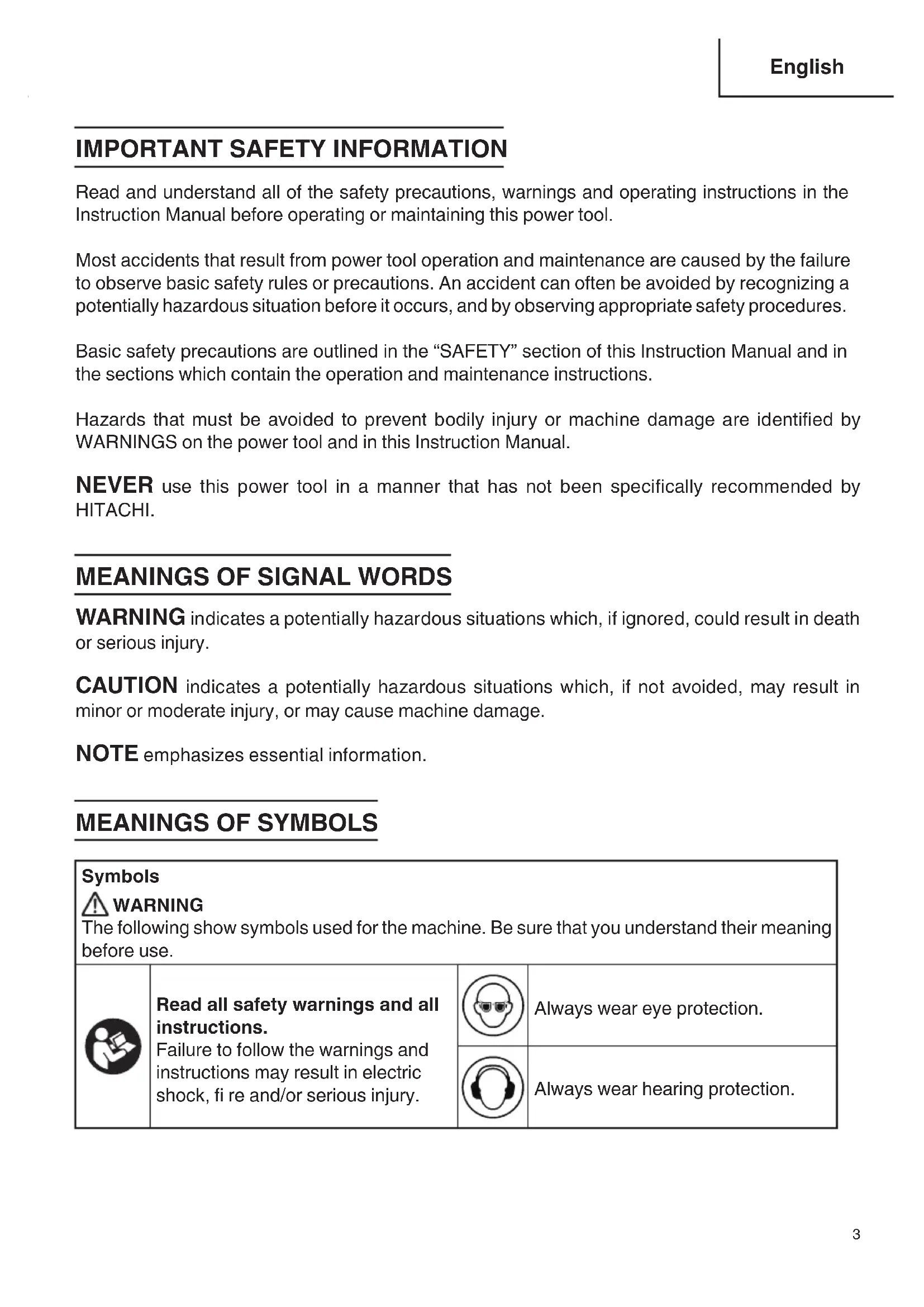
Symbols WARNING The following show symbols used for the machine. Be sure that you understand their meaning before use. Read all safety warnings and all instructions. Failure to follow the warnings and instructions may result in electric shock, fi re and/or serious injury. Always wear eye protection. Always wear hearing protection. 000BookC7WDMNAlowes.indb3000BookC7WDMNAlowes.indb3 2018/03/0916:58:062018/03/0916:58:064 English SAFETY
General Power Tool Safety Warnings
WARNING: * Read all safety warnings and all instructions. Failure to follow the
warnings and instructions may result in electric shock, fi re and/or serious injury. * Save all warnings and instructions for future reference.The term "power tool" in the warnings refers to your mains-operated (corded) power tool or battery-operated (cordless) power tool.WORK AREA SAFETY1. Keep work area clean and well lit. Cluttered or dark areas invite accidents.
2. Do not operate power tools in explosive atmospheres, such as in the presence of fl ammable
liquids, gases or dust. Power tools create sparks which may ignite the dust or fumes.
3. Keep children and bystanders away while operating a power tool. Distractions can cause you
to lose control.ELECTRICAL SAFETY
1. Power tool plugs must match the outlet. Never modify the plug in any way. Do not use any
adapter plugs with earthed (grounded) power tools. Unmodifi ed plugs and matching outlets will reduce risk of electric shock.
2. Avoid body contact with earthed or grounded surfaces, such as pipes, radiators, ranges and
refrigerators. There is an increased risk of electric shock if your body is earthed or grounded.
3. Do not expose power tools to rain or wet conditions. Water entering a power tool will increase
the risk of electric shock.
4. Do not abuse the cord. Never use the cord for carrying, pulling or unplugging the power tool.
Keep cord away from heat, oil, sharp edges or moving parts. Damaged or entangled cords increase the risk of electric shock.
5. When operating a power tool outdoors, use an extension cord suitable for outdoor use. Use
of a cord suitable for outdoor use reduces the risk of electric shock.
6. If operating a power tool in a damp location is unavoidable, use a residual current device
(RCD) protected supply. Use of an RCD reduces the risk of electric shock. NOTE: The term “residual current device (RCD)” may be replaced by the term “ground fault circuit interrupter (GFCl)” or “earth leakage circuit breaker (ELCB)”. 000BookC7WDMNAlowes.indb4000BookC7WDMNAlowes.indb4 2018/03/0916:58:072018/03/0916:58:075 English PERSONAL SAFETY
1. Stay alert, watch what you are doing and use common sense when operating a power
tool. Do not use a power tool while you are tired or under the infl uence of drugs, alcohol or medication. A moment of inattention while operating power tools may result in serious personal injury.
2. Use personal protective equipment. Always wear eye protection. Protective equipment such
as dust mask, non-skid safety shoes, hard hat, or hearing protection used for appropriate conditions will reduce personal injuries.
3. Prevent unintentional starting. Ensure the switch is in the off position before connecting to
power source and/or battery pack, picking up or carrying the tool. Carrying power tools with your fi nger on the switch or energizing power tools that have the switch on invites accidents.
4. Remove any adjusting key or wrench before turning the power tool on. A wrench or a key left
attached to a rotating part of the power tool may result in personal injury.
5. Do not overreach. Keep proper footing and balance at all times. This enables better control
of the power tool in unexpected situations.
6. Dress properly. Do not wear loose clothing or jewellery. Keep your hair, clothing and gloves
away from moving parts. Loose clothes, jewellery or long hair can be caught in moving parts.
7. If devices are provided for the connection of dust extraction and collection facilities, ensure
these are connected and properly used. Use of dust collection can reduce dust-related hazards.
POWER TOOL USE AND CARE
1. Do not force the power tool. Use the correct power tool for your application. The correct
power tool will do the job better and safer at the rate for which it was designed.
2. Do not use the power tool if the switch does not turn it on and off . Any power tool that cannot
be controlled with the switch is dangerous and must be repaired.
3. Disconnect the plug from the power source and/or the battery pack from the power tool
before making any adjustments, changing accessories, or storing power tools. Such preventive safety measures reduce the risk of starting the power tool accidentally.
4. Store idle power tools out of the reach of children and do not allow persons unfamiliar with
the power tool or these instructions to operate the power tool. Power tools are dangerous in the hands of untrained users.
5. Maintain power tools. Check for misalignment or binding of moving parts, breakage of parts
and any other condition that may aff ect the power tool’s operation. If damaged, have the power tool repaired before use. Many accidents are caused by poorly maintained power tools.
6. Keep cutting tools sharp and clean. Properly maintained cutting tools with sharp cutting
edges are less likely to bind and are easier to control.
7. Use the power tool, accessories and tool bits etc. in accordance with these instructions,
taking into account the working conditions and the work to be performed. Use of the power tool for operations diff erent from those intended could result in a hazardous situation. SERVICE
1. Have your power tool serviced by a qualifi ed repair person using only identical replacement
parts. This will ensure that the safety of the power tool is maintained.specially designed for your saw, for optimum performance and safety of operation. 000BookC7WDMNAlowes.indb5000BookC7WDMNAlowes.indb5 2018/03/0916:58:072018/03/0916:58:076 English Safety instructions for all saws CUTTING PROCEDURES
Keep hands away from cutting area and the blade. Keep your second hand on auxiliary handle, or motor housing. If both hands are holding the saw, they cannot be cut by the blade. NOTE: For curcular saws with 140 mm or smaller diameter blades, the “Keep your second hand on auxiliary handle, or motor housing“ may be omitted.
2. Do not reach underneath the workpiece. The guard cannot protect you from the blade
below the workpiece.
3. Adjust the cutting depth to the thickness of the workpiece. Less than a full tooth of the
blade teeth should be visible below the workpiece.
4. Never hold the workpiece being cut in your hands or across your leg. Secure the
workpiece to a stable platform. It is important to support the work properly to minimise body exposure, blade binding, or loss of control.
5. Hold the power tool by insulated gripping surfaces only, when performing an
operation where the cutting tool may contact hidden wiring or its own cord. Contact with a “live” wire will also make exposed metal parts of the power tool “live” and could give the operator an electric shock.
6. When ripping, always use a rip fence or straight edge guide. This improves the
accuracy of cut and reduces the chance of blade binding.
7. Always use blades with correct size and shape (diamond versus round) of arbor
holes. Blades that do not match the mounting hardware of the saw will run eccentrically, causing loss of control.
8. Never use damaged or incorrect blade washers or bolt. The blade washers and bolt
were specially designed for your saw, for optimum performance and safety of operation.
SPECIAL SAFETY RULES FOR KICKBACK
1. Kickback causes and related warnings:
Kickback is a sudden reaction to a pinched, bound or misaligned saw blade, causing an uncontrolled saw to lift up and out of the workpiece toward the operator.
When the blade is pinched or bound tightly by the kerf closing down, the blade stalls and the motor reaction drives the unit rapidly back toward the operator.
If the blade becomes twisted or misaligned in the cut, the teeth at the back edge of the blade can dig into the top surface of the wood causing the blade to climb out of the kerf and jump back toward the operator.
2. Kickback is the result of saw misuse and/or incorrect operating procedures or conditions
and can be avoided by taking proper precautions as given below:
Maintain a fi rm grip with both hands on the saw and position your arms to resist kickback forces. Position your body to either side of the blade, but not in line with the blade. Kickback could cause the saw to jump backwards, but kickback forces can be controlled by the operator, if proper precautions are taken. 000BookC7WDMNAlowes.indb6000BookC7WDMNAlowes.indb6 2018/03/0916:58:072018/03/0916:58:077 English
When blade is binding, or when interrupting a cut for any reason, release the trigger and hold the saw motionless in the material until the blade comes to a complete stop. Never attempt to remove the saw from the work or pull the saw backward while the blade is in motion or kickback may occur. Investigate and take corrective actions to eliminate the cause of blade binding.
When restarting a saw in the workpiece, center the saw blade in the kerf and check that the saw teeth are not engaged into the material. If saw blade is binding, it may walk up or kickback from the workpiece as the saw is restarted.
Support large panels to minimize the risk of blade pinching and kickback. Large panels tend to sag under their own weight. Supports must be placed under the panel on both sides, near the line of cut and near the edge of the panel.
Do not use dull or damaged blades. Unsharpened or improperly set blades produce narrow kerf causing excessive friction, blade binding and kickback.
Blade depth and bevel adjusting locking levers must be tight and secure before making the cut. If blade adjustment shifts while cutting, it may cause binding and kickback.
Use extra caution when sawing into existing walls or other blind areas. The protruding blade may cut objects that can cause kickback.
LOWER GUARD FUNCTION
1. Check lower guard for proper closing before each use. Do not operate the saw if the
lower guard does not move freely and close instantly. Never clamp or tie the lower guard into the open position. If the saw is accidentally dropped, the lower guard may be bent. Raise the lower guard with the lower guard lifting lever and make sure it moves freely and does not touch the blade or any other part, in all angles and depths of cut.
2. Check the operation of the lower guard spring. If the guard and the spring are not
operating properly, they must be serviced before use. Lower guard may operate sluggishly due to damaged parts, gummy deposits, or build-up of debris.
3. The lower guard shall be retracted manually only for special cuts such as “plunge
cuts” and “compound cuts”. Raise the lower guard by the lower guard lifting lever and as soon as the blade enters the material, the lower guard must be released. For all other sawing, the lower guard should operate automatically.
4. Always observe that the lower guard is covering the blade before placing the saw
down on bench or fl oor. An unprotected, coasting blade will cause the saw to walk backwards, cutting whatever is in its path. Be aware of the time it takes for the blade to stop after switch is released. OTHERS
1. ALWAYS wear proper apparel. Do not wear loose clothing, gloves, neckties, rings,
bracelets or other jewelry which may get caught in moving parts to lead personal injury. Wear protective hair covering to contain long hair.
2. ALWAYS wear eye protection. Any power tool can throw foreign objects into eyes and could
cause permanent eye damage. ALWAYS wear Safety Goggles (not glasses) that comply with ANSI Safety standard Z87.1. Everyday eyeglasses have only impact–resistant lenses. They ARE NOT safety glasses. 000BookC7WDMNAlowes.indb7000BookC7WDMNAlowes.indb7 2018/03/0916:58:072018/03/0916:58:078 English
3. Wear suitable personal protective equipment when necessary, this could include:
● hearing protection to reduce the risk of induced hearing loss;● eye protection; ● respiratory protection which are approved by NIOSH/OSHA to reduce the risk of inhalation of harmful dust; ● gloves for handling saw blades (saw blades shall be carried in a holder wherever practicable) and rough material.
4. Keep alert. Never operate the saw when you feel tired or when you are under the the
infl uence of any drugs, alcohol or medicationn that could aff ect your ability to use the tool properly.
5. Keep the working environment well ventilated. Some dust created by power sanding,
sawing, grinding, drilling and other construction activities contains chemicals to cause cancer, birth defects or other reproductive harm. Therefore, work in a well ventilated area, and work with approved safety equipment, such as those dust masks that are specially designed to fi lter out microscopic particles.
6. Avoid prolonged contact with dust from power sanding, sawing, grinding, drilling, and other
construction activities. Wear protective clothing and wash exposed areas with soap and water. Allowing dust to get into your mouth, eyes, or lay on the skin may promote absorption of harmful chemicals.
7. To prevent from fi re or toxic reactio, never use gasoline, naphtha acetone, lacquer thinner
or similar highly volatile solvents to clean the saw.
SPECIFIC SAFETY RULES AND SYMBOLS
1. Adjustments. Before cutting be sure depth and bevel adjustments are tight.
2. Avoid cutting nails. Inspect for and remove all nails from work piece before cutting.
3. When operating the saw, keep the cord away from the cutting area and position it
so that it will not be caught on the workpiece during the cutting operation. Operate with proper hand support, proper workpiece support, and supply cord routing away from the work area.
It is important to support the work piece properly and to hold the saw fi rmly to prevent loss of control which could cause personal injury. Fig. 1 illustrates typical hand support of the saw. Fig. 1
4. Place the wider portion of the saw base on that part of the work piece which is
solidly supported, not on the section that will fall off when the cut is made. As examples, Fig. 2 illustrates the RIGHT way to cut off the end of board, and Fig. 3 the WRONG way. If the work piece is short or small, clamp it down. DON’T TRY TO HOLD SHORT PLACES BY HAND! Fig. 2 Fig. 3
5. Never attempt to saw with the saw held upside down in a vise.
This is extremely dangerous and can lead to serious accidents. (Fig. 4) Fig. 4
6. Before setting the tool down after completing a cut, be sure that the lower blade
guard has closed and the blade has come to a complete stop.
7. Never touch moving parts.
Never place your hands, fi ngers or other body parts near the tool’s moving parts.
8. Never operate without all guards in place.
Never operate this tool without all guards or safety features in place and in proper working order. If maintenance or servicing requires the removal of a guard or safety feature, be sure to replace the guard or safety feature before resuming operation of the tool.
Don’t force small tool or attachment to do the job of a heavy-duty tool. Don’t use tool for purpose not intended —for example— don’t use the saw for cutting tree limbs or logs.
10. Never use a power tool for applications other than those specifi ed.
Operate the tool according to the instructions provided herein. Do not drop or throw the tool. Never allow the tool to be operated by children, individuals unfamiliar with its operation or unauthorized personnel.
12. Keep motor air vent clean.
The tool’s motor air vent must be kept clean so that air can freely fl ow at all times. Check for dust build-up frequently.
13. Operate power tools at the rated voltage.
Operate the power tool at voltages specifi ed on their nameplates. If using the power tool at a higher voltage than the rated voltage, it will result in abnormally fast motor revolution and may damage the unit and burn out the motor.
14. Do not run the saw while carrying it at your side.
15. Keep all screws, bolts and covers tightly in place.
Keep all screws, bolts, and plates tightly mounted. Check their condition periodically.
16. Do not use power tools if the housing or handle is cracked.
Cracks in the tool’s housing or handle can lead to electric shock. Such tools should not be used until repaired.
17. Blades and accessories must be securely mounted to the tool.
Prevent potential injuries to yourself or others. Blades, cutting implements and accessories which have been mounted to the tool should be secure and tight.
18. Never use a tool which is defective or operating abnormally.
If the tool appears to be operating unusually, making strange noises, or otherwise appears defective, stop using it immediately and arrange for repairs by a Hitachi authorized service center.
19. Carefully handle power tools.
Should a power tool be dropped or struck against hard materials inadvertently, it may be deformed, cracked, or damaged.
20. Do not wipe plastic parts with solvent.
Solvents such as gasoline, thinner benzine, carbon tetrachloride, and alcohol may damage and crack plastic parts. Do not wipe them with such solvents. Wipe plastic parts with a soft cloth lightly dampened with soapy water and dried thoroughly.
21. Never wear gloves made of material liable to roll up such as cotton, wool, cloth or
22. Defi nitions for symbols.
0 .......... no load speed ---/min ..... revolutions per minute ........... alternating current 000BookC7WDMNAlowes.indb10000BookC7WDMNAlowes.indb10 2018/03/0916:58:142018/03/0916:58:1411 English REPLACEMENT PARTS When servicing use only identical replacement parts. Repairs should be conducted only by a Hitachi authorized service center. GROUNDING
1. Grounding Instructions.
In the event of a malfunction or breakdown, grounding provides a path of least resistance for electric current to reduce the risk of electric shock. This power tool is equipped with 3-conductor type electric cord having an equipment- grounding conductor and a plug with a grounding pin, as shown in Fig. 5. The plug must be plugged into a matching receptacle that is properly installed and grounded in accordance with all local codes and regulations.
WARNING: Do not modify the provided plug if it does not fi t the receptacle.
Have a proper receptacle installed by a qualifi ed electrician. If repair or replacement of the electric cord or plug is necessary, do not connect the equipment-grounding conductor to a live terminal. Repair or replace damaged or worn cord immediately. This power tool is intended for use on a circuit with a receptacle similar to the one illustrated in Fig. 5.
WARNING: Always connect the power tool to a grounded metal, permanent wiring
system: or to a system having an equipment-grounding conductor. 3-Pronged PlugGrounding ProngProperly Grounded3-Pronged Receptacle Fig. 5 000BookC7WDMNAlowes.indb11000BookC7WDMNAlowes.indb11 2018/03/0916:58:142018/03/0916:58:1412 English
USE PROPER EXTENSION CORD
Make sure your extension cord is in good condition. Use only 3-conductor type extension cords that have 3-prong grounding plugs and 3-pole receptacles that accept the tool’s plug. When using an extension cord, be sure to use one heavy enough to carry the current your product will draw. An undersized cord will cause a drop in line voltage resulting in loss of power and overheating. Table shows the correct size to use depending on cord length and nameplate ampere rating. If in doubt, use the next heavier gage. The smaller the gage number, the heavier the cord.
WARNING: To avoid electrical shock hazard, never use this tool with a damaged
or frayed electrical cord or extension cord. Inspect all electrical cords regularly. Never use in or near water or in any environment where electric shock is possible.
SAVE THESE INSTRUCTIONS
NOTE: The information contained in this Instruction Manual is designed to assist you in the safe operation and maintenance of the power tool. Some illustrations in this Instruction Manual may show details or attachments that diff er from those on your own power tool. NEVER operate, or attempt any maintenance on the tool unless you have fi rst read and understood all safety instructions contained in this manual.
WARNING: Accessories for this power tool are mentioned in this Instruction
Manual. The use of any other attachment or accessory can be dangerous and could cause injury or mechanical damage. STANDARD ACCESSORIES
1. Blade wrench (1 piece)For how to use, refer to page 18, 31.2. Blade (2 pieces)
Fig. 8 NOTE: Accessories are subject to change without any obligation on the part of the HITACHI. OPTIONAL ACCESSORIES......sold separately (1) Rip fence (HKU# 372098) (Includes (2).) (2) Locking bolt Fig. 9 For how to use, refer to page 27. NOTE: Specifi cations are subject to change without any obligation on the part of HITACHI. 000BookC7WDMNAlowes.indb15000BookC7WDMNAlowes.indb15 2018/03/0916:58:182018/03/0916:58:1816 English APPLICATIONS The tool is designed for wood cutting applications.
- Use extra caution when cutting freshly cut green lumber, hardwood, wet wood, composite wood, pressure treated wood, wood containing knots or having other characteristics which may put a heavy load on the saw or blade. If this occurs, do not force the tool. Push the tool more slowly, but with enough force to keep working without much decrease in speed.
- To avoid serious injury, do not cut the metal with a metal cutting blade attached. Also, do not use for applications other than wood cutting.
PREPARATION BEFORE OPERATION
Make the following preparations before operating the power tool:
1. Saw blade mounting and dismounting
WARNING: * Do not use a blade larger than 7-1/4" (184 mm) in diameter. To avoid
injury from an accidental start, ensure the switch is OFF position and make sure the plug is not connected to the power source outlet.
- Make sure the blade is installed correctly and is tight before operating.
- The tool becomes hot after tool operation. To avoid burns, the blade replacement work should be done after tool has cooled suffi ciently.
- The blade with round-shaped arbor hole that can remove knockout must be removed in order to expose the center of the diamond- shaped arbor in use.
- Only blades with a diamond-shaped arbor center can be used on this saw. Never install the saw blade with the round-shaped arbor center to avoid possible personal injury and from causing damage to the saw. Remove the knockout from the blade (Fig. 10)
- Work only with knockout-capable blades. Do not do this work for knockout impossible blades.
- To avoid injury, always protect our eyes and hands when doing this work.
- To avoid injury or damage to blade, do not swing down the hammer full force.
- Do not hit the hammer directly against the blade.
- Make sure that all knockout parts have been removed and there are no cracks, warp, etc. on the blade. 000BookC7WDMNAlowes.indb16000BookC7WDMNAlowes.indb16 2018/03/0916:58:192018/03/0916:58:1917 English (1) Place the blade on a hollow support as shown in Fig. 10. (2) Put a cushion block on the center of the knockout. NOTE: The size of the cushion block must be larger than the center hole of the knockout and be smaller than the knockout. (3) Use a hammer to knock the cushion block, so the knockout will fall with the cushion block. (4) If the knockout sticks on the blade, remove the knockout by needle-nose pliers or by hands worn with work gloves. Mounting the blade (Fig. 11-a, Fig. 11-b Fig. 11-c, and Fig. 11-d)
WARNING: To avoid serious accident, ensure the switch is in the OFF position
and disconnect the plug from the receptacle during maintenance and inspection. (1) Unplug the saw from the outlet. (2) Place the provided blade wrench over the arbor bolt. (3) Press the arbor lock button, holding it in fi rmly while turning the blade wrench. This will engage the arbor lock allowing the arbor bolt to be loosened with the blade wrench. Continue to hold the arbor lock button while turning the wrench clockwise to loosen the arbor bolt. (4) Use the lower blade guard lifting lever to raise the lower blade guard. (5) Remove the arbor bolt and the outer blade collar. Do not remove the inner blade collar. NOTE: Pay attention to the pieces removed, noting their position and direction they face. Wipe the blade collars clean of any sawdust before installing a new blade. (6) Install a 7-1/4" (184 mm) blade with a diamond-shaped arbor center, making sure the rotation arrow on the blade matches the clockwise rotation arrow on the upper blade guard. (7) Place the blade onto the arbor and against the inner blade collar. Then, place the outer blade collar and thread the arbor bolt conterclockwise onto the arbor. NOTE:
- Always ensure the diamond-shaped arbor center of the blade aligns with the raised diamond-shaped arbor center on the inner blade collar.
- The fl at side of the outer blade collar must be placed against the blade. Do not install the outer collar with the curved side against the blade. (8) Place the blade wrench on the arbor bolt. (9) Press the arbor lock button, holding it in fi rmly while turning the blade wrench counterclockwise. Continue to press it in while tightening the arbor bolt securely. NOTE: Tighten so that the diamond-shaped arbor center of blade does not shift the diamond type protrusion of the inner blade collar. (Fig. 11-d) (10) Slowly release the lower blade guard lifting lever. Fig. 10 Hammer Hollow support Cushion block Knockout Blade 000BookC7WDMNAlowes.indb17000BookC7WDMNAlowes.indb17 2018/03/0916:58:202018/03/0916:58:2018 English (11) Be sure the arbor lock button is released so the blade turns freely. NOTE:
- Be sure the arbor lock button returns to release position after releasing the button.
- Be sure that the blade is securely and correctly fi xed. Dismounting the blade (Fig. 11-a, Fig. 11-b and Fig. 11-c) (1) Unplug the saw from the outlet. (2) Place the provided blade wrench over the arbor bolt. (3) Press the arbor lock button, holding it in fi rmly while turning the blade wrench. This will engage the arbor lock allowing the arbor bolt to be loosened with the blade wrench. Continue to hold the arbor lock button while turning the wrench clockwise to loosen the arbor bolt. (4) Use the lower blade guard lifting lever to raise the lower blade guard. (5) Remove the arbor bolt, the outer blade collar, and the blade. Do not remove the inner blade collar. NOTE: Pay attention to the pieces removed, noting their position and direction they face. Wipe the blade collars clean of any sawdust before installing a new blade. Lower blade guard lifting lever Lower blade guard Arbor bolt Fig. 11-a Fig. 11-b Arbor lock button 000BookC7WDMNAlowes.indb18000BookC7WDMNAlowes.indb18 2018/03/0916:58:202018/03/0916:58:2019 English Fig. 11-c Arbor bolt Outer blade collar Blade Inner blade collar (DO NOT REMOVE) Arbor Blade Outer blade collar Arbor bolt Inner blade collar (DO NOT REMOVE) Arbor Fig. 11-d Always mount with diamond-shape in alignment. Don’t mount with diamond-shape misaligned.
2. Blade wrench storage
For convenient storage and prevention of loss, there is a slot in rear side of the base plate for storing the blade wrench when not in use. Fig. 12 Blade wrench Base plate Always insert in the direction in which Blade wrench protrudes upwards. Don’t insert in the direction in which blade wrench protrudes downward. 000BookC7WDMNAlowes.indb19000BookC7WDMNAlowes.indb19 2018/03/0916:58:222018/03/0916:58:2220 English BEFORE USING
1. Make sure the power source is appropriate for the tool.
WARNING: Never connect the power tool unless the available AC power
source is of the same voltage as that specifi ed on the nameplate of the tool. Never connect this power tool to a DC power source.
2. Make sure the trigger switch is turned OFF.
WARNING: If the power cord is connected to the power source with the
trigger switch turned ON the power tool will start suddenly and can cause a serious accident. Press the trigger switch to turn on the saw; release it to shut the saw off . After releasing the trigger switch, make sure the trigger switch has gone all the way back and the switch is turned off . Fig. 13 Trigger switch
3. Check the tool for visible defects.
Confi rm that the tool is free of cracks or other visible damage or lack of parts.
4. Confi rm that the saw blade is attached securely to the power tool.
Using the supplied blade wrench, tighten the bolt on the saw blade spindle to secure the saw blade. For details, see Fig. 11-a, Fig. 11-b and Fig. 11-c and Fig. 11-d in the section on “Saw blade mounting and dismounting”.
5. Check the lower blade guard for operation.
WARNING: * Make absolutely sure that the safety cover is not fi xed. Also,
check and see if it can move smoothly. If the saw blade is kept exposed injury can result.
- If the safety cover should not move smoothly, never use it without repairing it. In such a case, get in touch with the HITACHI Authorized Service Center for necessary repair. 000BookC7WDMNAlowes.indb20000BookC7WDMNAlowes.indb20 2018/03/0916:58:282018/03/0916:58:2821 English The lower guard serves to protect your body from coming into contact with the saw blade. Make absolutely certain that the cover smoothly performs to cover the saw blade.
6. Confi rm the position of the arbor lock button before using the tool.
After installing the saw blade, confi rm that the arbor lock button has been returned to the released position before using the power tool (see Fig. 11-b).
7. Confi rm the tool’s power cord is not damaged.
WARNING: Repair or replace the power cord if an inspection indicates that it
When the work area is far away from the power source, use an extension cord of suffi cient thickness and rated capacity. The extension cord should be kept as short as practicable.
To prevent overheating, accidental stopping or intermittent operation, confi rm that the power cord plug fi ts properly in the electrical receptacle and does not fall out after it is inserted. Repair or replace the receptacle if it is faulty.
Always wear eye protection with side shields that meets the requirements of ANSI Standard Z87.1. Ordinary eyeglasses do not provide adequate protection because they do not contain impact resistant safety glass.
WARNING: Operating the tool without wearing proper eye protection may
result in serious injury.
11. Confi rming condition of the environment:
Confi rm that the work site is placed under appropriate conditions conforming to prescribed precautions. Fig. 14 Lower blade guard 000BookC7WDMNAlowes.indb21000BookC7WDMNAlowes.indb21 2018/03/0916:58:292018/03/0916:58:2922 English AFTER CONNECTING THE POWER PLUG TO AN APPROPRIATE AC POWER SOURCE, CHECK THE OPERATION OF THE TOOL AS FOLLOWS:
After confi rming that no one is standing behind, the power tool start and confi rm that no operating abnormalities exist before attempting a cutting operation.
13. Inspect the rotating stability of the saw blade.
For precise cutting, rotate the saw blade and check for defl ection to confi rm that the blade is not noticeably unstable; otherwise vibrations might occur and cause an accident.
14. Prepare a wooden workbench (Fig. 15)
Since the saw blade will extend beyond the lower surface of the workpiece, place the workpiece on a workbench when cutting. If a square block is utilized as a workbench, select level ground to ensure it is properly stabilized. An unstable workbench will result in hazardous operation. CAUTION: To avoid possible accident, always ensure that the portion of workpiece remaining after cutting is securely anchored or held in position. Workbench Saw blade Base Workpiece Fig. 15 000BookC7WDMNAlowes.indb22000BookC7WDMNAlowes.indb22 2018/03/0916:58:312018/03/0916:58:3123 English BEFORE CUTTING
WARNING: To avoid serious accident, ensure the switch is in the OFF position
and disconnect the plug from the receptacle during maintenance and inspection.
1. Cutting depth adjustment
WARNING: If the depth adjusting locking lever is loose, injury can result. Tighten
it securely after adjustment. (1) Lift the depth adjusting locking lever up to loose. (2) Move the base plate to obtain the desired cutting depth. (3) Setting the saw to an appropriate cutting depth minimizes blade friction, eliminates sawdust from between the teeth of the blade, allows faster cutting, and reduces kickback opportunities. For the most effi cient cutting action, place the material to be cut along the side of the blade and adjust the cutting depth so that the saw blade protrudes one tooth length from the material. NOTE: The scale on the side of the base plate is accurate only with the maximum cutting depth. (4) Press down the depth adjusting locking lever to tighten. NOTE: Always make sure the depth adjustment locking lever is locked in the down position before operating the saw. Fig. 16 Base plateone tooth lengthDepth adjusting locking lever 000BookC7WDMNAlowes.indb23000BookC7WDMNAlowes.indb23 2018/03/0916:58:312018/03/0916:58:3124 English
2. Bevel angle adjustment
The full range of the bevel adjustment is from 0° to 53°. Fig. 17-a Bevel adjusting locking lever Bevel indicator Fig. 17-b 45° bevel setting 53° bevel setting Detent setting plate Detent setting plate Fig. 17-c
WARNING: If the bevel adjusting locking lever is loose, injury can result. Tighten
it securely after adjustment. (1) Turn the bevel adjusting locking lever up to loose. (2) Adjust to the desired bevel angle pointed by the bevel indicator on the bevel scale. (3) Turn the bevel adjusting locking lever down to tighten. (Fig. 17-a) NOTE:
- If 45° bevel angle is necessary, turn the detent setting plate clockwise to achieve the 45° setting. (Fig. 17-b)
- If 53° bevel angle is necessary, turn the detent setting plate counterclockwise to achieve 53° setting. (Fig. 17-c)
3. 90° (0°) Bevel adjustment
WARNING: To ensure accurate cuts, alignment should be checked and
adjustments made prior to use. (1) Lift the bevel adjusting locking lever to set the saw to 90° (0°) and then tighten the lever. (2) Retract the lower blade guard and place the saw upside down. (3) Place a combination square against the blade and base plate to check whether the blade is 90° to the base plate. (4) If the blade is not 90° to the base plate, turn the hex screw on the bottom of the base plate by using 3 mm hex wrench to adjust. (5) Check the accuracy of the adjustment by an actual cut on a scrap piece of material. Bevel adjusting locking lever Hex screw Base plate Fig. 18 000BookC7WDMNAlowes.indb24000BookC7WDMNAlowes.indb24 2018/03/0916:58:322018/03/0916:58:3225 English
4. Detent setting plate adjustment
NOTE: In order to make the correct adjustment, make sure that the saw blade and base plate are right angles when the product is set at 90°. If the bevel accuracy adjustment is necessary, loosen the lock nut with a 7 mm or adjustable wrench and turn the hex screw in or out with a 2 mm hex wrench until the bevel accuracy is achieved. Then, tighten the lock nut. PRACTICAL APPLICATIONS
● Never touch the moving parts. ● Should the saw blade be stopped or make an abnormal noise during operation, turn off the switch immediately. ● Don't remove the saw from work piece during a cut while the saw blade is moving. ● Always wear eye protection with side shields that meets the requirements of ANSI Standard Z87.1. Ordinary eyeglasses do not provide adequate protection. ● Avoid cutting any material like metal, etc., that give off sparks. ● Do not use any abrasive wheels. ● Use only blade diameter specifi ed on the product nameplate. ● For your own safety, never connect the saw plug to any power source outlet until all assembly and adjustment are completed, and you have read and understood the safety and operating instructions. An accidental start-up can cause injury. CAUTION: ● Always take care in preventing the power cord from coming near the revolving saw blade. ● Before starting to saw, ensure that the saw blade has reached full speed revolution. IMPORTANT: Always make sure the depth adjustment locking lever is in the down position and locked before operating the saw.
(1) The front of the base plate has a 90° guide notch and a 45° guide notch for vertical and bevel cutting. The guide notches enable you to guide the saw along the cutting lines marked on the workpiece. (2) Also, the saw has the inner guide notches located on the insides of the base plate as shown in Fig. 20 to keep the straight cutting. Fig. 19 Hex screwLock nut 000BookC7WDMNAlowes.indb25000BookC7WDMNAlowes.indb25 2018/03/0916:58:352018/03/0916:58:3526 English Fig. 20 45° 90° 45° guide notch 90° guide notchInner guide notchesInner guide notchesBase plate
2. Using hanging hook
WARNING: To reduce the risk of injury from the saw falling on operators or
bystanders, make sure the saw is supported securely when using the hanging hook to hang the saw from a rafter, joist or other elevated support. (1) Turn the hanging hook away from the saw body to hang the saw from a rafter, joist or other elevated support.
WARNING: To reduce the risk of injury, do
not use the saw with the hanging hook rotated below the base plate. (2) When not in use, return the hanging hook back to the storage position until it latches against the saw body.
3. Using auxiliary handle
When operating the saw, use both hands to hold the saw fi rmly, one hand on the auxiliary handle and the other hand on the trigger switch handle, to increase the stability of the saw operation to avoid the possible kickback occurred. Hanging hook Fig. 21 Auxiliary handleTrigger switch handle Fig. 22 000BookC7WDMNAlowes.indb26000BookC7WDMNAlowes.indb26 2018/03/0916:58:362018/03/0916:58:3627 English
4. Turning the saw on
WARNING: To reduce the risk of serious personal injury, hold saw with both
hands when starting the saw to avoid kickback. (1) Using a pencil or marker mark the line to be cut on the workpiece. (2) Place the saw on the workpiece, align pre-marked guide line with the saw blade, using the guide notch at the front of the base plate. NOTE: This relationship of base plate to workpieces should remain unchanged regardless of the inclination of the base plate. (3) Use both hands to hold the saw fi rmly, one hand on the auxiliary handle and the other hand on the trigger switch handle. (4) The trigger switch should be turned ON by being pressed with one fi nger before the saw blade comes into contact with the workpiece. NOTE: The trigger switch is turned OFF when the trigger switch is released. (5) Moving the saw straight at a constant speed will produce optimum cutting. NOTE: This saw has no provision to lock the trigger in the on position and should never be locked on by any other methods. Trigger switch Pre-marked guide line Auxiliary handle Trigger switch handle Fig. 23
5. Installing the rip fence (optional accessories)
(1) Insert the rip fence through the holes of the base plate. (2) Adjust the rip fence to the desired position. (3) Insert and tighten the rip fence locking bolt. Fig. 24 Rip fence Base plate Rip fence locking bolt 000BookC7WDMNAlowes.indb27000BookC7WDMNAlowes.indb27 2018/03/0916:58:402018/03/0916:58:4028 English
WARNING: * To avoid serious accident, ensure the switch is OFF position, and
disconnect the plug from the receptacle before any adjustment.
- To avoid serious accident, make sure that the rip fence does not touch the saw blade before use. Ripping means to cut wider boards into narrower strips – cutting grain lengthwise. Therefore, it is recommended to use the Hitachi rip fence (optional accessory, refer to page 15) to provide the support and cut boards into the same width.
- Never secure the lower blade guard in a raised position. Never move the saw backwards when plunge cutting. This may cause the saw to raise up off the work surface which could cause injury.
- To avoid serious accident, ensure the trigger switch is on the OFF position, and disconnect the plug from the receptacle before any adjustment.
- Never tie or wedge the lower blade guard in a raised position. (1) Mark the desired cutting area clearly with lines all side. (See Fig. 26) (2) Set depth adjustment according to material to be cut. (3) Push the lower blade guard lifting lever all the way back, so the blade is exposed as shown in Fig. 26. (4) Tilt the saw forward and align the guide notch with the pre-marked guide line. (5) Release the lever. When the lower blade guard contacts the workpiece surface, it will be in the proper position to open freely when cutting is commenced. (6) Holding the saw in position, with the blade not contacting the work piece surface, pull the trigger switch. (7) After the saw has reached full speed, gradually lower rear end of the saw until its base plate rests on the work surface. Fig. 25 Rip fence Fig. 26 Trigger switch Lower blade guard lifting lever Auxiliary handle 000BookC7WDMNAlowes.indb28000BookC7WDMNAlowes.indb28 2018/03/0916:58:442018/03/0916:58:4429 English (8) Advance saw along the cutting line up to the corner. (9) Release trigger switch and allow the blade to stop completely before withdrawing the blade from the workpiece. Never under any circumstances pull the saw backwards while the blade is in motion, as kickback may result. (10) Use a jig saw or hand saw to cut the corners out clean. (11) When starting each new cut, repeat as above.
WARNING: Never hold the workpiece in your hands or across your leg while
cutting. Secure the workpiece to a stable platform. It is important to support the work properly to minimise body exposure, blade binding, or loss of control.
8. Appropriate support for cutting large workpiece
Fig. 27-a DON’T support the large workpiece away from the cut. Fig. 27-b ALWAYS support the large workpiece near the cut. Support Support When the support is away from the cutting path, it may cause the large workpiece to be curved. In such case, the blade is likely to be bound, causing a kickback and increasing the load to the motor. (Fig. 27-a) Therefore, to avoid the possible personal injury or kickback occurred, ALWAYS cut the large workpiece with the appropriate support which shall be near the cutting path. (Fig. 27-b) 000BookC7WDMNAlowes.indb29000BookC7WDMNAlowes.indb29 2018/03/0916:58:472018/03/0916:58:4730 English
MAINTENANCE AND INSPECTION
WARNING: To avoid an accident or personal injury, always confi rm that
the trigger switch is turned OFF and the power plug has been disconnected from the receptacle before performing any maintenance or inspection of this tool.
1. Inspecting the saw blade
Always replace the saw blade immediately upon the fi rst sign of deterioration or damage. A damaged saw blade can cause personal injury and a worn saw blade can cause ineff ective operation and possible overload to the motor. CAUTION: Never use a dull saw blade. When a saw blade is dull, its resistance to the hand pressure applied by the tool handle tends to increase, making it unsafe to operate the power tool.
2. Inspecting the carbon brushes (Fig. 28 and Fig. 29)
The carbon brushes in the motor are expendable parts. If the carbon brushes become excessively worn, motor trouble might occur. Therefore, inspect the carbon brushes periodically and replace them when they have become worn to the wear limit line as shown in Fig. 28. Also, keep the carbon brushes clean so that they will slide smoothly within the brush holders. Use a slotted screwdriver to turn the spring-loaded cap counterclockwise carefully to remove the cap on the side of the motor. Pull out the carbon brush and replace. The ears on the metal end of the assembly go in the same hole the carbon part fi ts into. Last, tighten the cap snugly, but do not overtighten. Repeat above procedure for the carbon brush located on the other side of the motor. NOTE: When replacing the carbon brushes, use only Hitachi carbon brushes. CAUTION: Using this saw with a carbon brush which is worn in excess of the wear limit will damage the motor. Fig. 29 Carbon brushSpring-loeded cap Fig. 28 Wear limit line11/16" (17 mm)1/4" (5.7 mm)
WARNING: * To avoid injury from an accidental start, ALWAYS make sure the
switch is in the “OFF” position, and the plug is not connected to the power source outlet.
- Always check the oil level before using the saw.
- Be careful, gear oil may be hot! Contact with hot oil may cause the personal injury.
- After using the saw, avoid touching the gear case, oil plug and peripheral parts which become high temperature after work to prevent personal injury.
- Be aware of any rotating parts or assembly for the possible burns caused by careless using.
- The maintenance should be carried out after the saw has cooled suffi ciently.
- To avoid injury accident and tool breakdown, do not put something other than gear oil such as water, mud, gasoline, metal or wood pieces in gear box. Also, do not use the tool with them it.
- Do not put used gear oil into this product. NOTE: Recommend time to replace gear oil: (1) After fi rst 10 hours of use, replace the gear oil. (2) When replacing the carbon brushes, replace the gear oil. (3) While using the saw, the abnormal sound is occurred from the gear box, replace the gear oil. (4) When the saw has been not used for a long time, replace the gear oil before using the saw because the gear oil may be deteriorated. (1) Turn counterclockwise to loosen the oil plug by using the blade wrench and remove it. (2) Pour out the lubricating oil of the gear box from the oil fi ll hole. (3) Slowly injection the gear oil. Fill the gear oil to reach the bottom of the oil fi ll hole thread. It is recommended to use only Mobilube HD 85W-140 API GL-5 oil. Using other oils may cause tool breakage and unsatisfactory temperatures. (4) Replace the oil plug and then tighten it by turning clockwise with the blade wrench. Oil plug Oil fi ll hole Fig. 30 000BookC7WDMNAlowes.indb31000BookC7WDMNAlowes.indb31 2018/03/0916:58:512018/03/0916:58:5132 English NOTE:
- Over-amount of the gear oil will cause the over-high temperature and over-high pressure of the gear box, which will lead to oil leakage.
- Replacing all old gear oil to the new one will keep the effi ciency of the saw.
- Do not use gear oil that has been used in this product for other purposes.
- Dispose of unnecessary gear oil according to local, state, federal laws and regulations.
4. About handling the motor
Winding of the motor is said to be the heart of this tool. Exercise utmost caution not to damage the winding by exposing it to wash oil or water. NOTE:
- Accumulation of dust and the like inside the motor can result in a malfunction.
- After using the motor for 50 hours or so, carry out no-load running, and blow in the dry air from a wind hole at the motor’s rear. Such action is eff ective to discharge dust and the like.
5. Inspecting the screws
Regularly inspect each component of the power tool for looseness. Re-tighten screws on any loose part.
WARNING: To prevent personal injury, never operate the power tool if any
components are loose.
6. Inspecting the lower blade guard for proper operation
Before each use of the tool, test the lower blade guard to assure that it is in good condition and that it moves smoothly. Never use the tool unless the lower blade guard operates properly and it is in good mechanical condition.
After operation of the tool has been completed, check that the following has been performed: (1) Trigger switch is in OFF position, (2) Power plug has been removed from the receptacle, When the tool is not in use, keep it stored in a dry place out of the reach of children.
Periodically remove chips, dust and other waste material from the surface of the power tool, especially from the inside of the lower guard with a damp, soapy cloth. To avoid a malfunction of the motor, protect it from contact with oil or water.
9. Service parts list
A: HKU# B: I.D. No. C: Description D: Size E: Qʼty 000BookC7WDMNAlowes.indb32000BookC7WDMNAlowes.indb32 2018/03/0916:58:522018/03/0916:58:5233 English CAUTION: Repair, modifi cation and inspection of Hitachi Power Tools must be carried out by a Hitachi Authorized Service Center. This Parts List will be helpful if presented with the tool to the Hitachi Authorized Service Center when requesting repair or other maintenance. In the operation and maintenance of power tools, the safety regulations and standards prescribed in each country must be observed. MODIFICATIONS: Hitachi Power Tools are constantly being improved and modifi ed to incorporate the latest technological advancements. Accordingly, some parts (i.e. code numbers and/or design) may be changed without prior notice.
All quality power tools will eventually require servicing or replacement of parts because of wear from normal use. To assure that only authorized replacement parts will be used and that the double insulation system will be protected, all service (other than routine maintenance) must be performed by an AUTHORIZED HITACHI POWER TOOL REPAIR CENTER ONLY. NOTE: Specifi cations are subject to change without any obligation on the part of HITACHI. 000BookC7WDMNAlowes.indb33000BookC7WDMNAlowes.indb33 2018/03/0916:58:522018/03/0916:58:5234 Français
propices aux accidents.
EXTERNAL TOOTH LOCK WASHER
Some dust created by power sanding, sawing, grinding, drilling, and other construction activities contains chemicals known to the State of California to cause cancer, birth defects or other reproductive harm. Some examples of these chemicals are:
Lead from lead-based paints,
Crystalline silica from bricks and cement and other masonry products, and
Arsenic and chromium from chemically-treated lumber. Your risk from these exposures varies, depending on how often you do this type of work.To reduce your exposure to these chemicals: work in a well ventilated area, and work with approved safety equipment, such as those dust masks that are specially designed to fi lter out microscopic particles.