
BM15 - Measuring equipment Megger - Free user manual and instructions
Find the device manual for free BM15 Megger in PDF.
| Product Type | Insulation Resistance Tester (Megohmmeter) |
| Brand | Megger |
| Model | BM15 |
| Test Voltages | 500 V, 1000 V, 2500 V, 5000 V DC |
| Insulation Measurement Range | 100 kΩ to 20 GΩ |
| Insulation Accuracy | ±2.5% of scale (0 to 30 °C) |
| Voltage Measurement | 0 to 600 V AC/DC (AC accuracy ±2.5%, DC unspecified) |
| Short-Circuit Current | 1.5 mA ± 0.5 mA |
| Maximum Load Capacitance | 5 µF |
| Power Supply | 8 LR6 (AA) alkaline or rechargeable batteries |
| Battery Life | Approximately 2000 tests of 5 seconds at 5 kV into 100 MΩ load |
| Display | Analog needle on logarithmic scale |
| Dimensions | 220 mm x 160 mm x 115 mm |
| Weight | Approximately 1.2 kg |
| Terminals | Terminals "+", "-", "G" (guard) with lock |
| Specific Functions | Automatic discharge, residual voltage display, automatic voltmeter mode |
| Supplied Accessories | 3 test leads 3 m with crocodile clips, user guide, bandwidth transparency, carrying case |
| Cleaning | Clean cloth dampened with soapy water or isopropyl alcohol |
| Safety | Double insulation (Class II), CE, measurement categories CAT II/III/IV |
| Warranty | 1 year |
Frequently Asked Questions - BM15 Megger
User questions about BM15 Megger
0 question about this device. Answer the ones you know or ask your own.
Ask a new question about this device
Download the instructions for your Measuring equipment in PDF format for free! Find your manual BM15 - Megger and take your electronic device back in hand. On this page are published all the documents necessary for the use of your device. BM15 by Megger.
USER MANUAL BM15 Megger
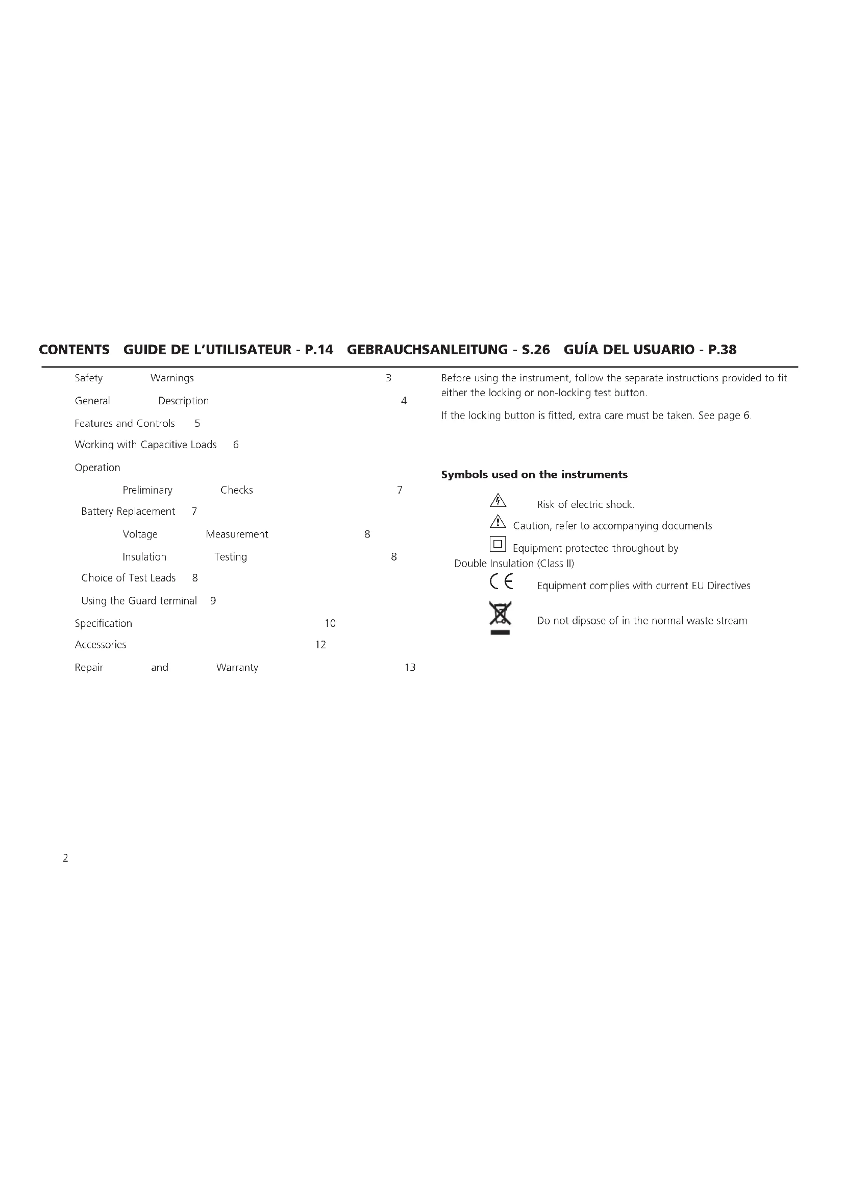
General Description 4
Features and Controls 5
Working with Capacitive Loads 6
Operation
Preliminary Checks 7
Battery Replacement 7
Voltage Measurement 8
Insulation Testing 8
Choice of Test Leads 8
Using the Guard terminal 9
Specification 10
Accessories 12
Repair and Warranty 13
Before using the instrument, follow the separate instructions provided to fit either the locking or non-locking test button.
If the locking button is fitted, extra care must be taken. See page 6.
Symbols used on the instruments
Risk of electric shock.
Caution, refer to accompanying documents
Equipment protected throughout by Double Insulation (Class II)

Equipment complies with current EU Directives

Do not dipsose of in the normal waste stream
SAFETYWARNINGS
'Safety Warnings' and 'Working with Capacitive Loads' must be read and understood before the instrument is used. Safety precautions must be observed during use.
The circuit under test must be switched off, de-energised and isolated before any test connections are made.
Circuit connections must not be touched during a test.
On completion of a test, decaying voltage across the terminals is indicated on the display. Capacitive load circuits must be discharged to below 60 V before disconnecting the test leads.
Capacitive load circuits should be shorted with a shorting link after discharge.
Remove the test leads from the instrument before opening the battery compartment.
Test leads and crocodile clips must be in good order, clean and with no broken or cracked insulation.
The instrument should not be used if any part of it is damaged.
U.K. Safety Authorities recommend the use of fused test leads when measuring voltage on high energy systems. See 'Choice of Test Leads'.
CAT II Measurement category II: Equipment connected between the electrical outlets and the user's equipment.
CAT III Measurement category III: Equipment connected between the distribution panel and the electrical outlets.
CAT IV Measurement category IV: Equipment connected between the origin of the low-voltage mains supply and the distribution panel.
NOTE - The instruments must only be used by suitably trained and competent persons.
NOTE
Users of this equipment and or their employers are reminded that Health and Safety Legislation requires them to carry out valid risk assessments of all electrical work so as to identify potential sources of electrical danger and risk of electrical injury such as from inadvertent short circuits. Where the assessments show that the risk is significant then the use of fused test leads constructed in accordance with the HSE guidance note GS38 'Electrical Test Equipment for use by Electricians' should be used. See 'Choice of Test Leads'.
The measurement leads provided with the BM15/MJ15 are rated CAT O, and are to be used for connection to low voltage (<33V) circuits only. Potentially hazardous circuits must be isolated and verified as safe using a suitably rated instrument before making any measurement connection using unrated leads. The CAT rating of the instrument is the same as the lowest rated part in the measurement connection.
GENERAL DESCRIPTION
BM15, and MJ15 testers are completely self-contained instruments designed for high voltage insulation resistance testing in the maintenance and servicing of rotating plant machinery, transformers, switchgear and industrial installations.
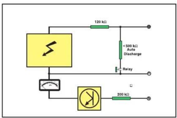
Tests can be performed at 500V 1000V,2500 V or 5000 V. Insulation measuring range is 100k to 20 G and Infinity. Automatic discharge for capacitive circuits under test is provided and decaying voltage displayed.
A guard terminal can be used to minimise the effects of surface leakage when carrying out insulation resistance tests.
Tests are initiated by pressing the BM15 'Test' button (or by turning the MJ15 generator handle). Releasing the 'Test' button (or ceasing handle rotation) causes the instrument to default to ac/dc voltmeter mode, with a discharge resistor internally connected across the terminals. This feature will give decaying voltage indication following the testing of equipment possessing capacitance.
The moving coil meter operates a black pointer to display the readings on a single logarithmic black scale on a white scale-plate for clarity of reading. The movement is resiliently mounted for field use.
A slide - in 'Pass Band' overlay can be inserted over the display. Appropriate Pass/Fail bands can be marked on these windows with a permanent marker for 'Go / No Go' testing.
BM15 is powered by eight 1,5 V (IEC LR6) cells.
Normal power for the MJ15 is by low voltage, hand cranked, brushless a.c generator. Fitting the battery container supplied, with eight 1,5 V IEC LR6 cells gives the instrument a dual (independent) supply capability. Both instruments are fitted with a battery check range, operated by pressing the 'Test' push button. Cranking the handle too slowly (<180 RPM) results in an
unstable pointer reading. Excess handle speed cannot harm the instrument as the output voltage is electronically regulated.
The case is robust, yet light-weight, made from a flame retardant ABS, with a polycarbonate display window. Mounted on top of the case is a 6 position, rotary, range selection switch and a 'Test' push button.
Three recessed sockets are provided, and marked ^+ ,and G . These have safety covers which open when the plugs are inserted. When inserted into the sockets, the shrouded test lead plugs lock into position. They are released by twisting the plug a quarter turn and pulling out.
For this reason, only the test leads supplied or suitable Megger replacement ones should be used.
Design safety features include:
External voltage, a.c. or d.c., displayed.
- Load automatically discharged at the end of a test, and decaying voltage displayed.
- Test leads can lock into the case to prevent accidental disconnection.
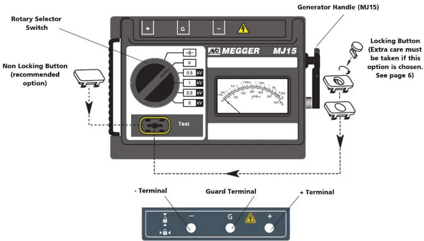
TO INSERT TERMINAL PLUGS, PUSH IN - TO RELEASE, TWIST A QUARTER TURN AND PULL OUT
WORKING SAFELY WITH CAPACITIVE LOADS

Circuit connections and the instrument terminals may become hazardous when connected to Capacitive loads.
- These instruments are designed to safely charge and discharge capacitive loads up to 5 F . To safeguard against malfunction however, you are advised to take your own precautions when working with capacitive loads. Remember that when charged, even low value capacitors can be fatal on contact.
- Extra care must be taken if the locking Test button is selected.
Do not forget to release a locked Test button and discharge any capacitance before touching the item under test or disconnecting the test leads.
- Circuit connections must not be touched when testing.
- Care must be taken to prevent capacitive circuits becoming disconnected during a test, leaving the circuit in a charged state.
- On completion of a test, the instrument indicates circuit decaying voltage. Do not disconnect test leads until the load capacitance has discharged to below 60V .
-
The voltmeter and automatic discharge feature of the instruments should be regarded as additional safety features and not a substitute for normal safe working practice.
-
If any part of the instrument is damaged, it should not be used, but returned to the manufacturer or an approved service organization for repair.
Preliminary Performance Checks
The instrument will operate in any position, but best results are achieved when the instrument is face up, on a firm level surface. This is particularly true for hand cranked units to obtain a crank speed of >180 rev/min.
1) If battery cells are fitted, switch to Battery Check range and press the 'Test' push button. Confirm that the pointer settles within the battery symbol portion of the scale.
2) With the test leads disconnected, set the rotary selector switch to the appropriate insulation range, press and hold down the 'Test' button, (or turn the generator handle). The meter pointer should move up the scale briefly and then return to the '∞' (infinity) position on the scale. This establishes that there is no leakage through the instrument itself.
3) Check that the test leads and crocodile clips are in good order, clean and with no broken or cracked insulation. Connect two of the test leads to the +^ and - terminals and ensure that their clips are not touching anything.
4) Press the 'Test' button again (or turn the generator handle) and observe the meter pointer. The pointer should rest over the position on the scale. If it does not, the test leads may be faulty and should be inspected more closely for damage. Replace them if necessary.
5) Connect the test lead clips together, press the 'Test' button (or turn the generator handle) and observe the meter pointer. The meter should read 0 . If it indicates infinity or a high resistance value the leads may be open circuit and should be inspected further. Replace them if necessary. (Shorting the leads together and obtaining a 0 reading also indicates that the instrument is working).
Battery Replacement

WARNING
The battery contacts are not isolated from the test leads. Remove the test leads from the instrument before opening the battery compartment.
The cells are housed in a battery compartment in the base of the instrument. To change the cells, use a screwdriver to remove the battery cover securing screws and lift off the battery compartment cover. Observing the correct polarity as marked on the battery housing, install 8 replacement IEC LR6 (AA) cells. Replace and secure the battery compartment cover on completion.
OPERATION
Voltage measurement
When switched to the 'V' position, the instrument measures up to 600 V a.c. to the specified accuracy of the instrument. DC voltage is also indicated on the display, but not to the specified accuracy. When not testing (i.e. in standby mode) and connected to a live circuit, the instruments default to voltmeter (0 to 600 Volts a.c. or d.c.) irrespective of the rotary switch position. Any voltage present will immediately be shown. Thus indication is given that the item has not been completely de-energized. The instrument also monitors circuit discharge when the 'Test' button is released following an insulation test on a capacitive item, e.g. a long cable.
Insulation Testing
After connecting the test leads to the instrument and carrying out the Preliminary Performance Checks:
1) Set the selector switch to the required test voltage. Connect the test leads to the isolated circuit to be tested, as follows:-
(a) For insulation tests to earth (ground):- Connect either test lead to earth (ground) or the frame of the equipment, and the other lead to that part of the circuit to be tested.
b) For insulation tests between wires: Connect a lead to the core of each of the wires.
2) Press the 'Test' button (or turn the generator handle).
3) The meter pointer will indicate the value of insulation resistance on the scale.
If a capacitive circuit is tested, the pointer will initially deflect towards 0 and then gradually rise to its final steady value as the capacitance is charged up to the output voltage of the tester.
If several successive readings of (infinity) are obtained, connect the two farthest ends of the test leads together and carry out a check on the leads. A 0Ω reading should result which double checks that the leads are not disconnected or broken and therefore, the insulation resistance readings are correct.
Capacitive circuits automatically discharge through the tester when the 'Test' button is released. Decaying discharge voltage will be indicated on the voltage scale. Wait a few moments for the voltage to decay to below 60V
Do not forget to release a locked Test button, and discharge any capacitance before touching the item under test, or disconnecting the test leads.
before disconnecting the test leads.
Choice of Test Leads
BM15/MJ15 are supplied with three unfused leads terminated in crocodile clips. These are the best leads to use for insulation tests on non-live circuits. The crocodile clips ensure that any capacitive load remains connected until it is automatically discharged at the end of a test.
GS 38 (UK Safety Authority Guidance Note) advises the use of fused test prods if the instrument is to be used for making voltage measurements on live, high energy circuits. These leads are available as an optional extra. See 'Accessories'.
Fused prods must not be used for insulation testing. If the fuse should rupture, or the prods lose contact during a test, the system under test would remain charged without any apparent evidence of danger!
Using the Guard terminal (G)
For basic insulation tests and where there is little possibility of surface leakage affecting the measurement, it is unnecessary to use the guard terminal (if the insulator is clean and there are unlikely to be any adverse current paths). However in cable testing, there may be surface leakage paths across the insulation between the bare cable and the external sheathing due to the presence of moisture or dirt. Where it is required to remove the effect of this leakage, particularly at high testing voltages, a bare wire may be bound tightly around the insulation and connected via the third test lead to the guard terminal 'G'.
The guard terminal is at the same potential as the negative terminal. Since the leakage resistance is effectively in parallel with the resistance to be measured, the use of the guard causes the current flowing through surface leakage to be diverted from the measuring circuit. The instrument therefore reads the leakage of the insulator, ignoring leakage across its surface.
Range: 100 kΩ to 20 GΩ (also 0 Ω and ∞)
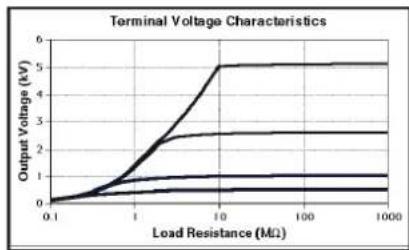
Test Voltages (d.c.): 500 V, 1000 V, 2500 V & 5000 V
Test Voltage Accuracy: ±5% of nominal test voltages on 20 MΩ load
Test Voltage Stability: <±1% (180 r.p.m. to 240 r.p.m. MJ15)
Insulation Accuracy see page 11
Short Circuit Current: 1,5mA± 0,5mA
Maximum capacitance of load: 5 F
Interference Rejection: 1 mA rms at 50 to 60 Hz
Discharge Resistor: <500 kΩ
Voltage
Range: 0 to 600 V a.c. indication of d.c.
Accuracy:
see
page
11
General
Overload rating: 720 V a.c. or d.c.
Scale Length: 72 mm (96°)
Power Supply: BM15 8 x LR6 (AA alkaline or rechargeable) cells
MJ15 Low voltage brushless Generator or 8 x LR6 (AA alkaline) cell battery
Battery life: Typically 2000 five second tests at 5kV on 100 MΩ load
Battery Indicator: Loaded battery test
Safety: IEC 61010-1
Non replaceable Fuse: 1 Amp, 250 V, HBC type (F) (20 mm x 5 mm) to IEC 127/1
This fuse protects the instrument against any faults occurring when using rechargeable batteries.
E.M.C: IEC 61326-1
Operational uncertainties: Refer to www.megger.com
Temperature Range:
Operating: 0^ to 30^ (32^ to 86^) at full specification
Operating: -20^ + to 50^ (-4^ to 122^) to temperature coefficient ± 0,1% /^ C
Storage: -25°C to 65°C (-13°F to 149°F)
Humidity: 90% RH maximum at 40^ (104°F)
Dimensions: 220mm× 160mm× 115mm (8,9 in x 6,3 in x 4,5 in)
Weight: BM15 Approx 1.2 kg
MJ15 Approx 1,6 kg, or 1,8 kg with battery holder and cells.
Cleaning: Wipe the disconnected instrument with a clean cloth dampened with soapy water or Isopropyl Alcohol (IPA)
***Relates to transient overvoltage likely to be found in fixed installation wiring.
*Relates to transient overvoltage likely to be found in special equipment or parts of equipment, telecommunication, electronic etc.
† Note: MJ15 will operate as normal by generator at full temperature range
BM15 will require new healthy battery cells to operate as normal at -20^
ACCESSIONS
SUPPLIED WITH THE INSTRUMENT
User
Guide
PART NUMBER
6172-209
Battery of 8 × 1,5 ~V LR6 (AA Alkaline) cells
3x3m HV leads 1002-531
Test Record Card (5 supplied) 6172-111
(U.S. 210949)
Carrying case with lead storage 6420-117
Slide in Pass Band overlay (5 supplied) 6121-401
AVAILABLE AS AN OPTIONAL EXTRA
5 kV Fused Prod Set 6320-240
5 kV Calibration Box - CB101 6311-077
Test Record Card (Pack of 20) 6111-216
PUBLICATIONS
'A Stitch In Time' AVTM21-P8B
'Lowdown on HV d.c. Testing' AVTM22P-1
The instrument circuit contains static sensitive devices, and care must be taken in handling the printed circuit board. If the protection of an instrument has been impaired it should not be used, and be sent for repair by suitably trained and qualified personnel. The protection is likely to be impaired if, for example, the instrument shows visible damage, fails to perform the intended measurements, has been subjected to prolonged storage under unfavourable conditions, or has been exposed to severe transport stresses.
New Instruments are Guaranteed for 1 Year from the Date of Purchase by the User.
Note: Any unauthorized prior repair or adjustment will automatically invalidate the Warranty.
Instrument Repair and Spare Parts
For service requirements for Megger Instruments contact:
Megger Limited or Megger
Archcliffe Road Valley Forge Corporate Center
Dover 2621 Van Buren Avenue
Kent, CT17 9EN. Norristown, PA 19403
England.
U.S.A.
Tel: +44 (0) 1304 502243 Tel: +1 (610) 676-8579
Fax: +44 (0) 1304 207342 Fax: +1 (610) 676-8625
umenquires@megger.com usenquires@megger.com
or an approved repair company.
Approved Repair Companies
A number of independent instrument repair companies have been approved for repair work on most Megger instruments, using genuine Megger spare
parts. Consult the Appointed Distributor / Agent regarding spare parts, repair facilities and advice on the best course of action to take.
Returning an Instrument for Repair
If returning an instrument to the manufacturer for repair, it should be sent freight pre-paid to the appropriate address. A copy of the Invoice and of the packing note should be sent simultaneously by airmail to expedite clearance through Customs. A repair estimate showing freight return and other charges will be submitted to the sender, if required, before work on the instrument commences.
End of life disposal
WEEE
The crossed out wheeled bin placed on the Megger products is a reminder not to dispose of the product at the end of it's product life with general waste.
Megger is registered in the UK as a Producer of Electrical and Electronic Equipment.
The Registration No is WEE/HE0146QT
Batteries
The crossed out wheeled bin placed on the batteries is a reminder not to dispose of them with general waste at the end of their life.
This product contains eight alkaline AA batteries located in the battery compartment on the rear of the instrument
Spent alkaline AA batteries are classified as Portable Batteries and should be disposed of in the UK in accordance with Local Authority requirements.
For disposal of batteries in other parts of the EU contact your local distributor. Megger is registered in the UK as a producer of batteries. The registration number is BPRN00142
GUIDE DE L'UTILISATEUR - TABLE DES MATIÈRES
DISPONIBLE EN OPTION AVEC SUPPLEMENT
'Lowdown on HV d.c. Testing
AVTM22P-1
AVTM21-P8B
RéPARATION ET GARANTIE
Archcliffe Road Valley Forge Corporate Center
Dover 2621 Van Buren Avenue
Kent CT17 9EN Norristown, PA 19403
Angleterre USA
Tél: +44 (0) 1304 502243 Tél: +1 (610) 676-8579
Fax: +44 (0) 1304 207342 Fax: +1 (610) 676-8625
REPARATUREN UND GARANTIE
Archcliffe Road Valley Forge Corporate Center
Dover 2621 Van Buren Avenue
Kent CT17 9EN Norristown, PA 19403
England USA
Tel: +44 (0) 1304 502243 Tel: +1 (610) 676-8579
Fax: +44 (0) 1304 207342 Fax: +1 (610) 676-8625
Precisión (a 0 - 30°C):
Archcliffe Road Valley Forge Corporate Center
Dover 2621 Van Buren Avenue
Kent, CT17 9EN Norristown, PA 19403
Inglaterra EE.UU.
Tel.: +44 (0) 1304 502243 Tel.: +1 (610) 676 8579
Fax: +44 (0) 1304 207342 Fax: +1 (610) 676 8625
Archcliffe Road, Dover
Kent CT17 9EN England
T (0) 1304502101
F (0) 1 304 207342
Megger
4271 Bronze Way, Dallas, Texas
75237-1019 USA
T 18007232861
T12143333201
F12143317399
Megger
Z.A. Du Buisson de la Couldre
23 rue Eugene Henaff
78190 TRAPPES France
T 130.16.08.90
F 134.61.28.77
OTHER TECHNICAL SALES OFFICES
Toronto CANADA, Sydney AUSTRALIA, Mumbai India, Madrid SPAIN and the Kingdom of BAHRAIN.
Megger products are distributed in 146 countries worldwide.
This instrument is manufactured in the United Kingdom.
The company reserves the right to change the specification or design without prior notice.
Megger is a registered trademark
Part No. 6172-209 V16 Printed in England 12/14
www.megger.com


- Symbols used on the instruments
- SAFETYWARNINGS
- NOTE - The instruments must only be used by suitably trained and competent persons.
- NOTE
- GENERAL DESCRIPTION
- WORKING SAFELY WITH CAPACITIVE LOADS
- Do not forget to release a locked Test button and discharge any capacitance before touching the item under test or disconnecting the test leads.
- Preliminary Performance Checks
- Battery Replacement
- WARNING
- OPERATION
- Voltage measurement
- Insulation Testing
- Choice of Test Leads
- Using the Guard terminal (G)
- Voltage
- General
- ACCESSIONS
- SUPPLIED WITH THE INSTRUMENT
- PART NUMBER
- AVAILABLE AS AN OPTIONAL EXTRA
- PUBLICATIONS
- New Instruments are Guaranteed for 1 Year from the Date of Purchase by the User.
- Instrument Repair and Spare Parts
- Approved Repair Companies
- Returning an Instrument for Repair
- End of life disposal
- Batteries
- GUIDE DE L'UTILISATEUR - TABLE DES MATIÈRES
- DISPONIBLE EN OPTION AVEC SUPPLEMENT
- RéPARATION ET GARANTIE
- REPARATUREN UND GARANTIE
Brand : Megger
Model : BM15
Category : Measuring equipment