
AHQ140CV1 - Air Conditioning DAIKIN - Free user manual and instructions
Find the device manual for free AHQ140CV1 DAIKIN in PDF.
Download the instructions for your Air Conditioning in PDF format for free! Find your manual AHQ140CV1 - DAIKIN and take your electronic device back in hand. On this page are published all the documents necessary for the use of your device. AHQ140CV1 by DAIKIN.
USER MANUAL AHQ140CV1 DAIKIN
Português Manual De Funcionamento Aparelho Sem Fios CVR-OM-SLM9-0312(0)SIESTA-EN.ind1 1CVR-OM-SLM9-0312(0)SIESTA-EN.ind1 1 5/2/12 5:02:01 PM5/2/12 5:02:01 PMCVR-OM-SLM9-0312(0)SIESTA-EN.ind2 2CVR-OM-SLM9-0312(0)SIESTA-EN.ind2 2 5/2/12 5:02:02 PM5/2/12 5:02:02 PMi Disposal Requirements The batteries supplied with the controller are marked with this symbol. This means that the batteries shall not be mixed with unsorted household waste. If a chemical symbol is printed beneath the symbol, this chemical symbol means that the battery contains a heavy metal above a certain concentration. Possible chemical symbols are: n Pb: lead (>0,004%) Waste batteries must be treated at a specialized treatment facility for re-use. By ensuring correct disposal, you will help to prevent potential negative consequences for the environment and human health. Please contact your local authority for more information. Battery
2) Quantity: 2 pieces
,VNBOEBZMBCJSMJLUFWFSJMFOQJMMFSCVTFNCPMMFJ¿BSFUMFONJ¿UJS
Hold Key to change Swing Mode
4. QUIET Activate/deactivate Quiet function
5. SET TEMP UP Increase set temperature in °C or °F
6. SET TEMP DOWN Decrease set temperature in °C or °F
12. ON/OFF On/Off the unit with overriding all the timer settings
13. REAL TIME CLOCK (RTC) Enable/disable the Real Time Clock (RTC) setting mode
NOTE: Turbo and quiet function are for selected models only. MODE TURBODELAYTIMERTIMER ON OFF TIMER
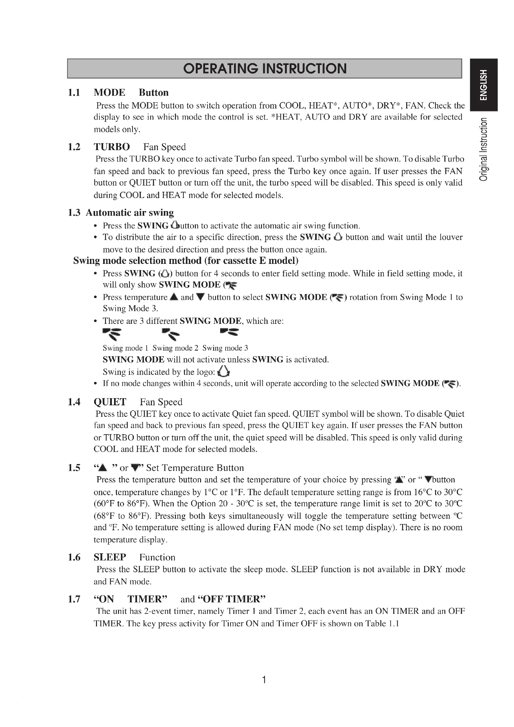
Press the MODE button to switch operation from COOL, HEAT*, AUTO*, DRY*, FAN. Check the display to see in which mode the control is set. *HEAT, AUTO and DRY are available for selected models only.
Press the TURBO key once to activate Turbo fan speed. Turbo symbol will be shown. To disable Turbo fan speed and back to previous fan speed, press the Turbo key once again. If user presses the FAN button or QUIET button or turn off the unit, the turbo speed will be disabled. This speed is only valid during COOL and HEAT mode for selected models.
1.3 Automatic air swing
Press the SWING button to activate the automatic air swing function. To distribute the air to a specific direction, press the SWING button and wait until the louver move to the desired direction and press the button once again. Swing mode selection method (for cassette E model) Press SWING ( ) button for 4 seconds to enter field setting mode. While in field setting mode, it will only show SWING MODE ( ). Press temperature and button to select SWING MODE ( ) rotation from Swing Mode 1 to Swing Mode 3. There are 3 different SWING MODE, which are: Swing mode 1 Swing mode 2 Swing mode 3 SWING MODE will not activate unless SWING is activated. Swing is indicated by the logo: If no mode changes within 4 seconds, unit will operate according to the selected SWING MODE ( ).
Press the QUIET key once to activate Quiet fan speed. QUIET symbol will be shown. To disable Quiet fan speed and back to previous fan speed, press the QUIET key again. If user presses the FAN button or TURBO button or turn off the unit, the quiet speed will be disabled. This speed is only valid during COOL and HEAT mode for selected models.
1.5 “ ” or “ ” Set Temperature Button
Press the temperature button and set the temperature of your choice by pressing “ ” or “ ” button once, temperature changes by 1°C or 1°F. The default temperature setting range is from 16°C to 30°C (60°F to 86°F). When the Option 20 - 30ºC is set, the temperature range limit is set to 20ºC to 30ºC (68°F to 86°F). Pressing both keys simultaneously will toggle the temperature setting between ºC and ºF. No temperature setting is allowed during FAN mode (No set temp display). There is no room temperature display.
Press the SLEEP button to activate the sleep mode. SLEEP function is not available in DRY mode and FAN mode.
1.7 “ON TIMER” and “OFF TIMER”
The unit has 2-event timer, namely Timer 1 and Timer 2, each event has an ON TIMER and an OFF TIMER. The key press activity for Timer ON and Timer OFF is shown on Table 1.1
ON Timer 1 ON Timer 2 OFF Timer 1 OFF Timer 2 Deactivated Deactivated Deactivated Deactivated Activated Deactivated Activated Deactivated Deactivated Activated Deactivated Activated Activated Activated Activated Activated All timers are event-triggered timers and can be overridden by the ON/OFF button and Override function. Set Event 1 and Event 2 Timers Process for Timer ON and Timer OFF is the same. Press and hold Timer ON/OFF key for 3 seconds to go into timer setting mode. (Icon ON 1 or OFF 1 will blink) Press UP or DOWN to select Timer 1 or Timer 2 to set. (‘1’ blinking indicate that Timer 1 is currently selected, ‘2’ blinking indicate that Timer 2 is currently selected) Press Timer ON/OFF key again to confirm. (Day will blink next) Press UP or DOWN to select the day. Press Timer ON/OFF key again to confirm the day. (Hour will blink next) Press UP or DOWN to change the hour. Press Timer ON/OFF key again to confirm the hour. (Minute will blink next) Press UP or DOWN to change the minute. Press Timer ON/OFF key again to confirm the minute. Each timer (Timer 1 ON or Timer 1 OFF or Timer 2 ON or Timer 2 OFF) will only be set separately after all 7 steps, if there is no key operation for 5 seconds during setting the timer, it will automatically exits from setting mode and no changes will be made. ON/OFF timer will be checked every 1 minute. It is not advisable to set ON TIMER and OFF TIMER to have same values. Shall these occur, the effective timer will be treated with priority as stated in Table 1.2. Example: ON TMR 2 settings: DAY – TUE, TIMER – 5.00pm OFF TMR 1 settings: DAY – TUE, TIMER – 5.00pm Outcome when RTC reaches 5.00pm on TUE: when unit is on, no respond. when unit is off, unit will trigger to on. Table 1.2: Timer Priority Priority Timer 1 (Highest) ONTMR2 2 OFFTMR2 3 ONTMR1 4 (Lowest) OFFTMR1 Upon IR reception, IR wireless remote controller will override ON TIMER 2 and OFF TIMER 2 settings.
Press the D ELAY TIMER key once will activate the delay timer function for 1 hour. An indicator “OVERRIDE” will show on the LCD. Press the same key again will increase the setting to 2 hours. An indicator “OVERRIDE” will be shown. Subsequent press will deactivate the delay timer function. After the delay timer is completed, the delay timer function is deactivated and the logo is OFF. All other timers will be r esumed.
1.9 FAN Speed Function
Fan speed can be changed via pressing the FAN key: Low > Med > High > Auto > *FAN speed is not available in DRY mode.
Starting Operation: Press the ON/OFF button, the LCD will show full display and the unit is turned on. Stopping Operation: Press the ON/OFF button, the LCD will show real time clock only and the unit is turn off.
1.11 Power up Settings
The unit will start up with main board’s last state setting during power up. If last state information is not available, the unit will use the default settings. The default settings are as below: Unit: Off Mode: Cool Fan Speed: High
RTC: 12:00AM, MONDAY
RTC is shown on screen during the unit ON or OFF except for power failure or error code. Set RTC Setting Press RTC key one time will activate RTC setting mode. (Day will blink) Press UP or DOWN to select the day. Press RTC again to confirm the day. (Hour will blink next) Press UP or DOWN to change the hour. Press RTC again to confirm the hour. (Minute will blink next) Press UP or DOWN to change the minute. Press RTC again to confirm the minute. RTC will only be set after all 7 steps, if there is no key operation for 5 seconds during setting the RTC, it will automatically exits from setting mode and no changes will be made on the setting.
These key lock function inhibits any setting change. Press and hold both TURBO and QUIET keys for 5 seconds will activate/deactivate the key lock function; “KEYLOCK” will be shown/disappear on LCD. Upon all the keys are locked, only ON/OFF, TURBO and QUIET (to unlock) can be pressed.
Battery backup is used to retain the RTC and 7-days programmable timer settings during power down for a minimum of 1 month continuous for every new set of battery installed. For unit without battery backup, the default setting will be 12:00am on Monday and timer clear during power up.
1.15 Error Indicator
If any abnormal condition detected, an error code will be shown. Error code is displayed by using RTC segments (blink), which mean whenever there is error occur, RTC will not be shown instead of the error code. The format for the error code will be as following: DX Error Code Error Description Room Sensor Open or Short E1 Indoor Coil Sensor Open E2 Outdoor Coil Sensor Open E3 Compressor Overload/Indoor Coil Sensor Short/Outdoor Coil Sensor Short E4 Gas Leak E5 Water Pump Fault E6 Outdoor Coil Sensor Exist (MS model) E7 Hardware Error (Tact Switch Pin Short) E8 Indoor Fan Feedback Error E9 EEPROM Error EE CW Error Code Error Description Room Sensor Open or Short E1 Pipe Water Sensor Open or Short E2 Pipe Water Temperature Poor E4 Pipe Water Temperature Bad/Fault E5 Water Pump Error E6 Hardware Error (Tact Switch Pin Short) E8 Indoor Fan Feedback Error E9 Fault Diagnosis (for inverter only) If there is any abnormal condition detected, ARCWB wired controller will blink the error code ERROR CODE MEANING 00 NORMAL
AH ELECTRICAL AIR CLEANER ABNORMAL
C9 INDOOR ROOM THERMISTOR SHORT/OPEN
COMPRESSOR DISCHARGE PIPE THERMISTOR SHORT/OPEN/MISPLACED
J5 SUCTION PIPE THERMISTOR SHORT/OPEN
J6 OUTDOOR HEAT EXCHANGER THERMISTOR SHORT/OPEN J7 SUBCOOLING HEAT EXCHANGER THERMISTOR SHORT/OPEN
J8 LIQUID PIPE THERMISTOR SHORT/OPEN
J9 GAS PIPE THERMISTOR SHORT/OPEN
L5 IPM ERROR/IGBT ERROR
The unit has 2 jumpers option to control the board function. Table 2.0: Summary of Hardware Settings OPTION With Jumper Without Jumper Set Temp. Range Set temp. range from 20°C – 30°C Set temp. range from 16°C – 30°C (Default) TURBO_QUIET Disable turbo and quiet fan speed (Default) Enable turbo and quiet fan speed
- Only applicable to model with built in Turbo or Quiet features.
The following accessories are included together with this manual. If any part is missing, contact your dealer immediately. Remote controller Wooden screw (2 pieces) & machine screw (2 pieces) Instruction manual Battery
3.2 Step-by-step guide
Open the clip on the top of the controller first follow by the bottom clip. Remove the top case of the controller from the bottom case. Fix the bottom case to the wall with the 2 screw provided. Then insert the connection wire through the slot on the upper center case as shown. Insert back the bottom clip first then snap the upper part shut.
LCD Remote (Top case) Connection wires 2 x Wooden screw LCD Remote (Bottom case)
(Cool (Froid) / Heat (Chauffage) / Auto / Dry (Sec) / Fan (Ventilation)
RTC: 12:00AM, MONDAY
RTC: 12:00AM, MONDAY
A6 INNENLÜFTER, MOTOR ANOMAL
RTC: 12:00AM, MONDAY
A1 PCB-FOUT BINNENSHUIS
A3 AFVOERPOMP ABNORMAAL
A5 ANTIVRIES (KOELING)/WARMTEWISSELAAR OVERVERHIT (VERWARMING)
A6 VENTILATORMOTOR BINNENSHUIS ABNORMAAL
AH ELEKTRISCHE LUCHTREINIGER ABNORMAAL
C4 WARMTEWISSELAAR BINNENSHUIS (1) THERMISTOR KORTSLUITING/OPEN
C5 WARMTEWISSELAAR BINNENSHUIS (2) THERMISTOR KORTSLUITING/OPEN
C7 FOUT SCHAKELAAR UITERSTE STAND LAMELLEN
C9 THERMISTOR KAMER BINNENSHUIS KORTSLUITING/OPEN
4-OM-SLM9-0312(0)SIESTA-NL.indd 44-OM-SLM9-0312(0)SIESTA-NL.indd 4 5/7/12 12:02:32 PM5/7/12 12:02:32 PM5 NEDERLANDS FOUTCODE BETEKENIS