
D2HND012 - Boiler DAIKIN - Free user manual and instructions
Find the device manual for free D2HND012 DAIKIN in PDF.
| Product type | Wall-mounted condensing boiler |
| Brand | Daikin |
| Model | D2HND012 |
| Category | Boiler |
| Dimensions (H x W x D) | 695 x 440 x 295 mm |
| Weight | 37 kg |
| Power supply | 230 V / 50 Hz |
| Maximum power consumption | 92 W (D2C20) / 112 W (D2C24) |
| Standby power consumption | 2.7 W |
| IP protection rating | IPX5D |
| Heating operating pressure (min./max.) | 0.6 / 3.0 bar |
| Maximum heating circuit temperature | 80 °C |
| Domestic hot water pressure (min./max.) | 0.05 / 1 MPa |
| Domestic hot water temperature (min./max.) | 35 / 60 °C |
| Expansion vessel capacity | 10 litres |
| Expansion vessel initial pressure | 1 bar |
| Gas type | Natural gas (G20/G25) or LPG (G31) |
| Nominal gas inlet pressure (G20/G25/G31) | 20 / 25 / 37 mbar |
| Domestic hot water flow rate (ΔT=30°C) | 14 l/min (D2C20) / 16 l/min (D2C24) |
| Part load efficiency (30%) | 108.9 % (D2C20) / 109.1 % (D2C24) |
| NOx class | 6 |
| Safety systems | Overheat thermostat, frost protection, low water safety, flame ionization, 3 bar safety valve, automatic air vents, pump and 3-way valve anti-blocking |
| Main functions | Central heating and instantaneous domestic hot water production, electronic regulation, automatic gas-air adaptation, condensing system |
| Maintenance and cleaning | Annual compulsory maintenance by a professional; filling the condensate trap before commissioning; regular water pressure check |
| Spare parts and repairability | Use exclusively original Daikin spare parts |
| General information | 52-page installation and user manual; warranty subject to registration |
Frequently Asked Questions - D2HND012 DAIKIN
User questions about D2HND012 DAIKIN
0 question about this device. Answer the ones you know or ask your own.
Ask a new question about this device
Download the instructions for your Boiler in PDF format for free! Find your manual D2HND012 - DAIKIN and take your electronic device back in hand. On this page are published all the documents necessary for the use of your device. D2HND012 by DAIKIN.
USER MANUAL D2HND012 DAIKIN
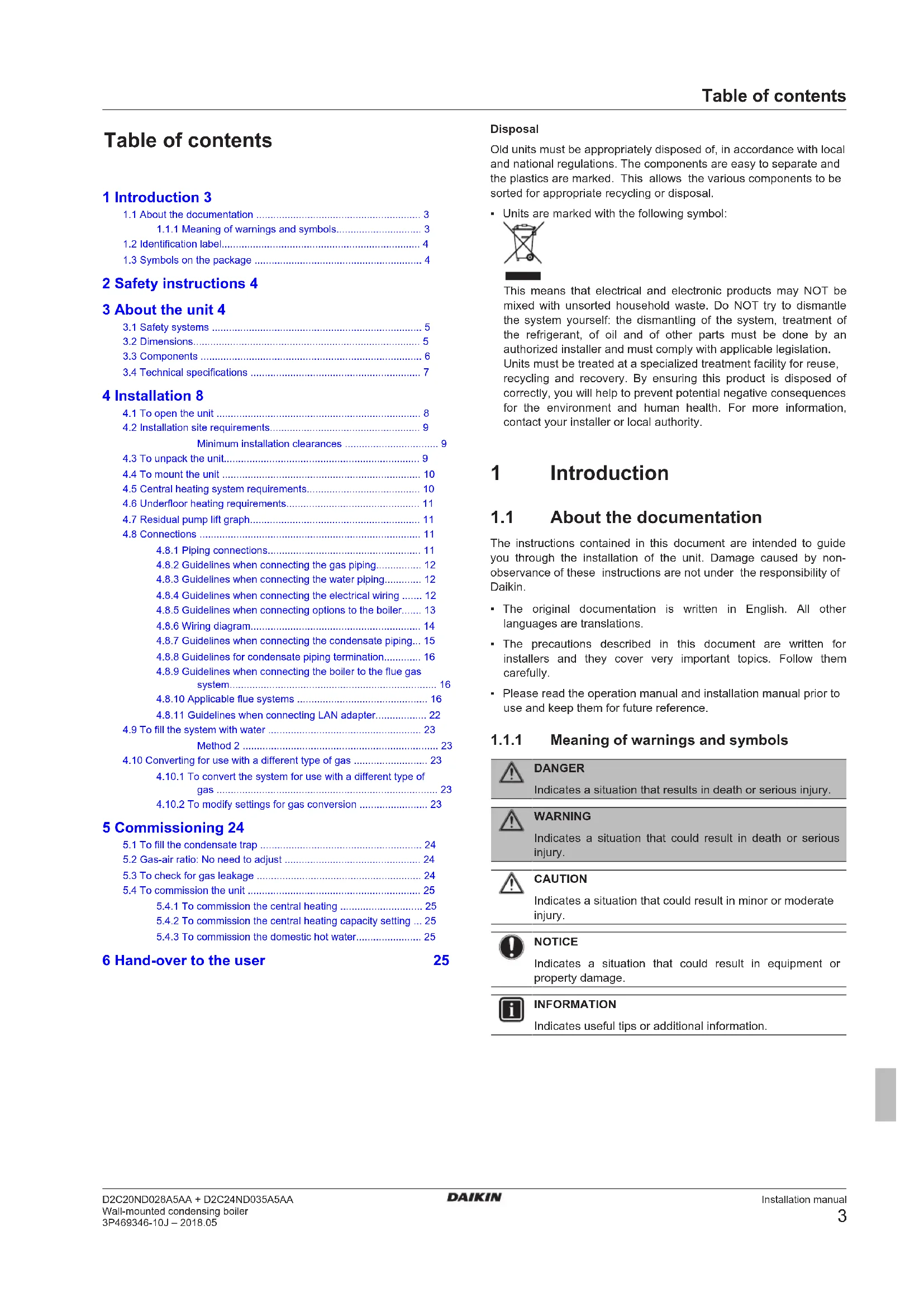
Wall-mounted condensing boiler
natural_image
Technical line drawing of a mechanical device with a central cylindrical component and two labeled sections (no text or symbols)D2C20ND028A5AA
D2C24ND035A5AA
Installation manual Wall-mounted condensing boiler
Ostend, 2nd of April 2018
Table of contents
1 Introduction 3
1.1 About the documentation .... 3
1.1.1 Meaning of warnings and symbols.... 3
1.2 Identification label.... 4
1.3 Symbols on the package 4
2 Safety instructions 4
3 About the unit 4
3.1 Safety systems 5
3.2 Dimensions.... 5
3.3 Components 6
3.4 Technical specifications 7
4 Installation 8
4.1 To open the unit 8
4.2 Installation site requirements....9
Minimum installation clearances 9
4.3 To unpack the unit....9
4.4 To mount the unit 10
4.5 Central heating system requirements.... 10
4.6 Underfloor heating requirements.... 11
4.7 Residual pump lift graph.... 11
4.8 Connections 11
4.8.1 Piping connections.... 11
4.8.2 Guidelines when connecting the gas piping.... 12
4.8.3 Guidelines when connecting the water piping..... 12
4.8.4 Guidelines when connecting the electrical wiring ..... 12
4.8.5 Guidelines when connecting options to the boiler..... 13
4.8.6 Wiring diagram.... 14
4.8.7 Guidelines when connecting the condensate piping... 15
4.8.8 Guidelines for condensate piping termination.... 16
4.8.9 Guidelines when connecting the boiler to the flue gas system.... 16
4.8.10 Applicable flue systems 16
4.8.11 Guidelines when connecting LAN adapter.... 22
4.9 To fill the system with water 23
Method 2 23
4.10 Converting for use with a different type of gas 23
4.10.1 To convert the system for use with a different type of gas 23
4.10.2 To modify settings for gas conversion 23
5 Commissioning 24
5.1 To fill the condensate trap 24
5.2 Gas-air ratio: No need to adjust 24
5.3 To check for gas leakage 24
5.4 To commission the unit 25
5.4.1 To commission the central heating 25
5.4.2 To commission the central heating capacity setting ... 25
5.4.3 To commission the domestic hot water.... 25
6 Hand-over to the user
25
Disposal
Old units must be appropriately disposed of, in accordance with local and national regulations. The components are easy to separate and the plastics are marked. This allows the various components to be sorted for appropriate recycling or disposal.
- Units are marked with the following symbol:
This means that electrical and electronic products may NOT be mixed with unsorted household waste. Do NOT try to dismantle the system yourself: the dismantling of the system, treatment of the refrigerant, of oil and of other parts must be done by an authorized installer and must comply with applicable legislation. Units must be treated at a specialized treatment facility for reuse, recycling and recovery. By ensuring this product is disposed of correctly, you will help to prevent potential negative consequences for the environment and human health. For more information, contact your installer or local authority.
1 Introduction
1.1 About the documentation
The instructions contained in this document are intended to guide you through the installation of the unit. Damage caused by non-observance of these instructions are not under the responsibility of Daikin.
- The original documentation is written in English. All other languages are translations.
- The precautions described in this document are written for installers and they cover very important topics. Follow them carefully.
- Please read the operation manual and installation manual prior to use and keep them for future reference.
1.1.1 Meaning of warnings and symbols

DANGER
Indicates a situation that results in death or serious injury.

WARNING
Indicates a situation that could result in death or serious injury.

CAUTION
Indicates a situation that could result in minor or moderate injury.

NOTICE
Indicates a situation that could result in equipment or property damage.

INFORMATION
Indicates useful tips or additional information.
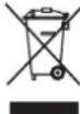
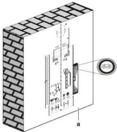
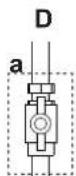
1.2 Identification label
You can find data about the unit on its identification label, which is located at the bottom of the right cover of the unit.
natural_image
Isometric line drawing of a mechanical device with a central knob and mounting base (no text or symbols)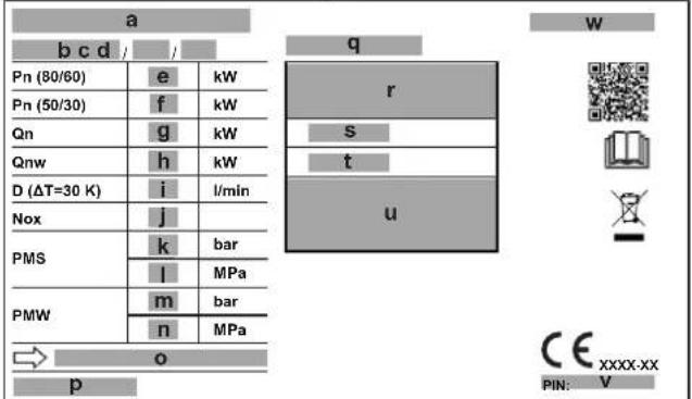
a Product number
b Electrical supply
c Maximum electrical power consumption
d Degree of protection
e Nominal heat output range @ 80/60
f Nominal heat output range @ 50/30
g Nominal heat input range
h Nominal heat input range (Domestic hot water)
i Hot water amount @ DT=30
j NOx class
k Maximum central heating pressure (bar)
I Maximum central heating pressure (MPa)
m Maximum domestic hot water pressure (bar)
n Maximum domestic hot water pressure (MPa)
o Country of destination(s)
p Country of origin
q Serial number
r Appliance type
s Efficiency class
t Gas category
u Gas type and supply pressure
v PIN number
v Product type
1.3 Symbols on the package

This is a fragile piece of equipment: Please provide a dry storage space for the unit.

This is a fragile piece of equipment: Please be very careful not to drop.

Store the unit in a flat position as indicated on the box.

No more than five boxes should be stacked on top of each other.
2 Safety instructions
These instructions are exclusively designed for qualified competent persons.
- Work on gas units must only be carried out by a qualified gas fitter.
- Work on electrical equipment must only be carried out by a qualified electrician.
- The system must be commissioned by a qualified competent person.

WARNING
A qualified person shall explain the operating principles and the use of the unit to the user. The user is not allowed to perform any modifications, maintenance or repairs on the unit, unless otherwise stated, or have the such performed by unauthorised third parties. Otherwise, the unit warranty becomes void.

DANGER
Isolate the boiler from the power mains before working on it.

WARNING
Unit installation, commissioning, repair, configuration and service must be performed by qualified competent persons in accordance with local standards and regulations. Incorrect installation of this unit may harm the user and his/her surroundings. The manufacturer is not responsible for any malfunctions and/or damage that may occur this way.

DANGER
Flammable fluids and materials must be stored at least 1 metre away from the boiler.

WARNING
To ensure faultless operation, long term availability of all functions and long working life of the boiler only use original spares.
3 About the unit
This Daikin unit is a wall-mounted gas-fired condensing boiler that can supply heat to central heating systems, as well as supply domestic hot water. Depending on settings, it is possible to use the unit solely for hot water or solely for central heating. Hot water supply type can be instantaneous or by means of a hot water storage tank. Heating only boilers do not supply domestic hot water. The type of the boiler can be recognized from the model name written on the identification label. See table below:
| Model | Type | Domestic hot water supply |
| D2C20ND028A5AAD2C20ND028 | Instantaneous | |
| D2C24ND035A5AAD2C24ND035 | Instantaneous |
A control unit, which contains a user interface, controls the ignition, safety systems, and other actuators. User interaction is provided via that user interface, which is composed of an LCD screen, push buttons, and two dials, and which is located on the front cover of the unit.
3.1 Safety systems
The unit is equipped with several safety systems, to protect it against dangerous conditions:
Flue safety system: This is controlled by the flue gas temperature sensor located on the flue outlet part of the boiler. It is activated when the flue gas temperature exceeds safety limits.
Overheating safety system: This is controlled by the safety limiting thermostat. It is located on the main heat exchanger and stops the unit when the flow temperature reaches 100^ C, to avoid boiling of the water, which may damage the unit.
Pump anti-blockage system: The pump operates for 30 seconds every 24 hours during long periods of inactivity to ensure it does not get stuck. To enable this function, the unit must be connected to the power supply.
Three-way valve anti-blockage system: In cases where the unit is non-operational for prolonged periods of time, the three-way valve switches its position every 24 hours to prevent it from getting stuck. To enable this function, the unit must be connected to the power supply.
Safety against dry operation: This is controlled by the pressure sensor. It turns off the unit and ensures system safety when the water pressure of the heating installation falls below 0.6 bar for any reason.
Flame ionisation control: This is controlled by the ionisation electrode. It checks whether a flame forms on the burner surface or not. If there is no flame, it turns the unit off to stop gas flow and warns the user.
High pressure protection:
- Pressure sensor: When heating system pressure reaches 2.8 bar, control unit stops heating operation thus preventing the pressure from rising.
- Safety valve: When the water pressure of the heating circuit exceeds 3 bar, some water is automatically drained from the safety valve to keep the pressure below 3 bar thus protecting the boiler and heating installation.
Automatic air vents: There are two air vents; one on the pump, other on the heat exchanger. They help discharging the air inside the installation and heating circuit to avoid air traps and consequent operational problems.
Frost protection safety system: This function protects the unit and heating installation from frost damages. It is controlled by the flow temperature sensor, which is located at the outlet of the main heat exchanger. This protection activates the boiler pump when the water temperature drops below 13°C and it activates the burner when the water temperature drops below 8°C. The unit keeps running until the temperature reaches 20°C. To enable this function, the unit must be connected to the power supply and its main gas valve must be open. Any damage caused by frost is not covered by the warranty.
Low voltage safety system: This is controlled by the control unit. When the supply voltage drops below 170 Volt, the boiler goes to error mode. It is a blocking error and the boiler will operate without reset after supply voltage is above 180 Volt. It is recommended to use a voltage regulator of suitable power and type in locations with voltage fluctuations below this limit for faultless operation.
High electric supply current protection system: A fuse on the control unit protects equipment and wiring against the damaging effects of electrical faults which is caused by excess currents, and disables equipment which is faulty. The fuse "blows" (opens) when the current carried exceeds the rated value for an excessive time.
Automatic by-pass system: This ensures that the flow is at all times continued, to avoid overheating of the heat exchanger. This system is also supported with a special by-pass function in the control unit software.
Combustion control safety system: Boiler control unit monitors the flame to avoid bad combustion and risky conditions. It also makes self-inspection against its own malfunctioning and to keep emissions always at a low level.
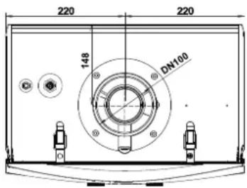
3.2 Dimensions
Top view
Front view and right side view
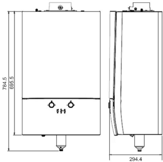
Bottom view of model D2C20ND028A5AA and D2C24ND035A5AA

3.3 Components
Components of models D2C20ND028A5AA and D2C24ND035A5AA
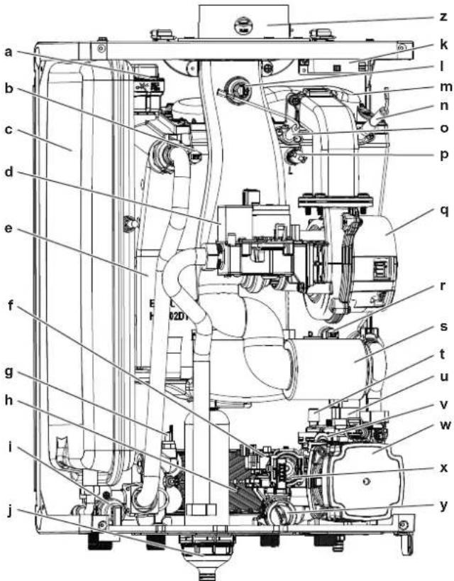
a Automatic air vent (heat exchanger)
b Flow temperature sensor
c Expansion vessel (10 litres)
d Gas valve
e Heat exchanger
f 3-way valve stepper motor
g Domestic hot water temperature sensor
h Plate heat exchanger
i Safety valve (3 bar)
j Condensate trap
k Ignition transformer
I Flue gas temperature sensor
n Burnerhood
n Ignition electrode
- Ionisation electrode
p High limit thermostat
q Fan
r Return temperature sensor
s Silencer
t Automatic air vent (pump)
u Water pressure sensor
v By-pass
w Boiler pump
x Domestic hot water flow sensor
y Domestic hot water flow limiter
z Flue gas adapter
3.4 Technical specifications
| Technical specifications Unit D2C20ND028A5AA D2C24ND035A5AA | ||||
| Heat Input Range(Qn) kW 4.8-19.2 4.8-23.5 | ||||
| Nominal Heat Output Range (Pn) at 80-60°C kW 4.6-18.8 4.6-22.9 | ||||
| Nominal Heat Output Range (Pn) at 50-30°C kW 5.2-20.0 5.2-24.0 | ||||
| Efficiency (30% partial load at 30°C return temperature) % 108.9 109.1 | ||||
| Central Heating Circuit | ||||
| Operating Pressure (min./max.) bar 0.6 / 3.0 | ||||
| Heating Circuit Temperature Interval (min./max.) °C 30 / 80 | ||||
| Domestic Hot Water Circuit | ||||
| Hot Water Amount DT: 30°C I/min 14 16 | ||||
| Hot Water Amount DT: 35°C I/min 12 14 | ||||
| Comfort Class (EN13203) | — | *** | ||
| Water Installation Pressure (min./max.) | MPa | 0.05 / 1 | ||
| Domestic Hot Water Temperature Interval (min./max.) | °C 35 / 60 | |||
| Domestic Hot Water Circuit Type | — | instantaneous | ||
| General | ||||
| Expansion Vessel Initial Pressure | bar | 1 | ||
| Expansion Vessel Capacity | I | 10 | ||
| Electrical Connection | V AC/Hz | 230/50 | ||
| Electrical Power Consumption (max.) | W | 92 | 112 | |
| Standby Electrical Power Consumption | W | 2.7 | ||
| IP Rating | — | IPX5D | ||
| Boiler Weight | kg | 37 | ||
| Boiler Dimensions (Height x Width x Depth) | mm | 695 x 440 x 295 | ||
| Flue outlet diameter | mm | 60 / 100 | ||
| Combustion specifications | Unit D2C20ND028A5AA D2C24ND035A5AA | |||
| Gas Category | — | II2NDF | ||
| Nominal Gas Inlet Pressure (G20/G25/G31) mbar 20 / 37 | ||||
| G20 Gas Inlet Pressure (min./max.) | mbar | 17 / 25(1) | ||
| G25 Gas Inlet Pressure (min./max.) | mbar | 20 / 31 | ||
| G31 Gas Inlet Pressure (min./max.) | mbar | 25 / 45 | ||
| Natural Gas (G20) Consumption (min./max.) | m3/h | 0.51 / 2.04 | 0.51 / 2.45 | |
| Natural Gas (G25) Consumption (min./max.) | m3/h | 0.59 / 2.35 | 0.59 / 2.85 | |
| LPG (G31) Consumption (min./max.) | m3/h | 0.2 / 0.98 | 0.2 / 1.19 | |
| Combustion products mass flow rate (min./max.) (G20) | g/s | 2.2 / 12.35 | 2.2 / 15.47 | |
| Combustion products mass flow rate (min./max.) (G31) | g/s | 2.2 / 12.02 | 2.2 / 15.22 | |
| Combustion products temperature (min./max.) (G20) | °C | 57.5 / 76.4 | 57.5 / 81.7 | |
| Combustion products temperature (min./max.) (G31) | °C | 57.5 / 74.5 | 57.2 / 80.2 | |
| CO2Emission at nominal and minimum heat input (G20) | % 8.8±0.8 | |||
| CO2Emission at nominal and minimum heat input (G31) | % | 11.3 / 10.2±1.0 | ||
| NOx Class | — | 6 | ||
(a) 20 / 30 for Hungary
| Energy-related products (ErP) specifications | Symbol | Unit | D2C20ND028A5AA | D2C24ND035A5AA |
| Model | — — | D2C20ND028 | D2C24ND035 | |
| Condensing boiler | — — | YES | YES | |
| Low-temperature ^(b) boiler | — — | NO | NO | |
| B1 boiler | — — | NO | NO | |
| Cogeneration space heater | — — | NO | NO | |
| Combination heater | — — | YES | YES | |
| Central heating efficiency class | — — | ****/A | ||
| Rated heat output | P_rave | kW | 19 | 23 |
| Useful heat output at rated heat output and high-temperature regime ^(c) | P_i | kW | 18.8 | 22.9 |
| Useful heat output at 30% of rated heat output and low-temperature regime ^(d) | P_i | kW | 6.3 | 7.7 |
| Seasonal space heating energy efficiency | _i | % | 93 | |
| Useful efficiency at rated heat output and high-temperature regime ^(e) | n_i | % | 88.1 | 87.9 |
| Useful efficiency at 30% of rated heat output and low-temperature regime ^(f) | n_i | % | 98.1 | 98.2 |
| Auxiliary electricity consumption | ||||
| At full load | eI_max | kW | 0.0292 | 0.0311 |
| At part load | eI_min | kW | 0.0087 | 0.0093 |
| In standby mode | P_sb | kW | 0.004 | |
| Other items | ||||
| Standby heat loss | P_sby | kW | 0.0651 | |
| Ignition burner power consumption | P_gt | kW | — | |
| Annual energy consumption | Q_HE | GJ | 36 | 43 |
| Sound power level, indoors (at maximum heat input) | L_V4 | dB | 50 | 53 |
| Emissions of nitrogen oxides | NO_x | mg/kWh | 31 | 32 |
4 Installation
| Energy-related products (ErP) specifications Symbol Unit D2C20ND028A5AA D2C24ND035A5AA | ||||
| Domestic hot water parameters | ||||
| Declared load profile — — XL | ||||
| Daily electricity consumption Q | okc | kWh 0.153 C.204 | ||
| Annually electricity consumption AEC kWh 33 44 | ||||
| Water heating energy efficiency η | vh | % 84 83 | ||
| Water heating energy efficiency class — — A | ||||
| Daily fuel consumption | Qfuel | kWh 23.25 30.26 | ||
| Annual fuel consumption | AFC | GJ | 18 23 | |
(a) High-temperature regime means 60°C return temperature at heater inlet and 80°C flow temperature at heater outlet.
(b) Low temperature means for condensing boilers 30°C, for low-temperature boilers 37°C and for other heaters 50°C return temperature (at heater inlet).
4 Installation
4.1 To open the unit

WARNING
Only qualified competent persons are allowed to open the unit.
Certain actions explained in this document, such as gas conversion, optional equipment connection, require that the front cover is opened.
1 Loosen the screw that holds the right mounting clips (1).
2 Dismantle the two mounting clips that hold the front cover (2).
3 Remove the front cover forwards (3).
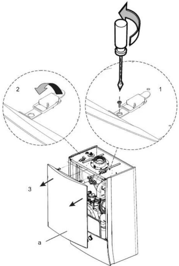
a Front cover
4 Loosen the two screws of the control panel (4).
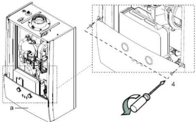
a Control panel
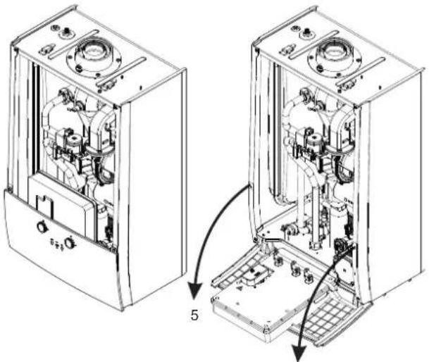
5 Pull the control panel forwards (5).
4.2 Installation site requirements

WARNING
The boiler must be installed by a qualified installer in accordance with local and national regulations.

WARNING
The following instructions shall be observed when determining the installation site.
- Mount this unit on vertical, flat walls only.
a Vertical, flat wall
- The boiler can be installed outdoors in a partially protected location. A partially protected location is a place where the boiler is not exposed to the direct action and to the penetration of atmospheric precipitation (rain, snow, hail,...).
The boiler can also be installed inside of an outside wall using the appropriate in-wall kit.
In case of outdoor installation, use the antifreeze kit (DRANTIFREEZxx) to prevent the piping and condensate trap from freezing. - Flammable fluids and materials must be stored at least 1 metre away from the boiler.
- The wall on which the unit is mounted should be strong enough to carry the unit's weight. Build a reinforcement if necessary.
- The following minimum clearances are required for servicing: 180 mm above the casing*, 200 mm below, and 10 mm at each side. 500 mm at the front clearance may be realised by opening a cupboard door. See "Minimum installation clearances" on page 9.
- For easier use of control panel, it is recommended that boiler bottom is 1500 mm from the floor, for easier part replacement side clearances should be 50 mm where applicable. See "Minimum installation clearances" on page 9.
- If the boiler is installed in a room or compartment, it does not require a dedicated ventilation for combustion air. If however installed in a room containing a bath or a shower, then particular reference is drawn to the current I.E.E. Wiring Regulations, local Building Regulations or any other local regulations currently in service.
- The intake air must not include chemicals that may cause corrosion, toxic gas formation and even risk of explosion.
- If the wall on which the unit is mounted, is flammable, a non-flammable material must be placed between the wall and the unit and also at all locations through where the flue piping passes.
Minimum installation clearances
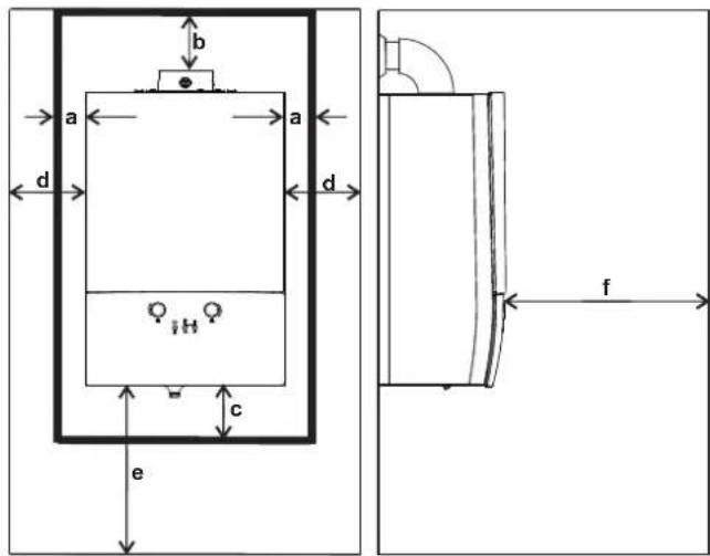
| Minimum allowable clearances | |
| a, sides 10 mm | |
| b, Above the casing* 180 mm | |
| c, below 255 mm | |
| f, in front | 500 mm |
| Recommended clearances for easy servicing | |
| d, sides 50 mm | |
| e, below (from the floor) | 1500 mm |
* 180 mm is for the case that 60/100 90° elbow is connected to the flue outlet of the boiler.
b = 270 mm in case that 60/100 to 80/80 adapter + 90°
elbow 80 are connected to the flue outlet of the boiler.
b = 280 mm in case that 60/100 to 80/125 adapter + 90°
elbow 80/125 are connected to the flue outlet of the boiler.
4.3 To unpack the unit
1 Unpack the unit as shown on top of the packing case. The following items must be included in the package:
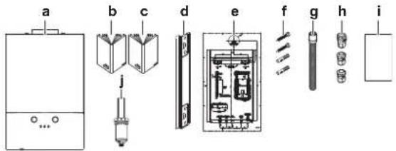
a Boiler
b Operation manual
c Installation manual
d Wall-mounting bracket
e Installation template
f Dowels and screws
g Condensate hose
h Cable glands 2×PG 7, 1×PG 9
i Energy label
j Condensate trap
2 Check the contents of the package. If any of them is damaged or missing, contact your dealer.

CAUTION
Store the remaining parts of the package (cardboard, plastic, etc.) in a place children cannot reach. The manufacturer is not responsible for any accidents and/or damage that may occur this way.
4.4 To mount the unit
1 The mounting template shows the position for the horizontal flue. If there is no hole in the wall for the flue piping, drill one. If there is already a hole in the wall for the flue piping, you can use this hole as a starting point to determine the position of the mounting bracket, according to the template. Flue duct must incline 3° away from the unit, to allow the condensate to drain back to the boiler.
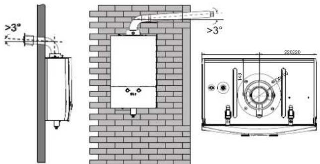
2 Drill holes for the mounting bracket ( 10 mm). Fasten the mounting bracket to the wall according to mounting template.
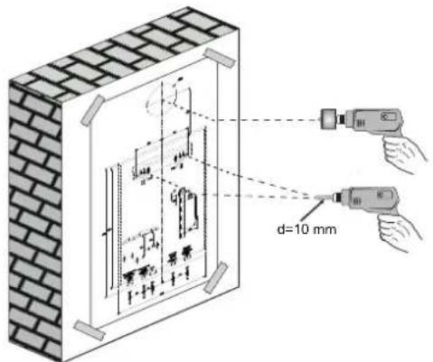
3 Hang the unit on the bracket. Make sure the unit is latched to the bracket.

natural_image
Diagram of a washing machine with a brick wall and internal components, showing airflow direction (no text or symbols)4.5 Central heating system requirements
Expansion vessel sizing
The boiler is equipped with an 10 litre expansion vessel that has initial charge pressure of 1 bar.
Sufficiency of the incorporated expansion vessel for the central heating circuit that the boiler is to be connected to depends on system charge pressure and water temperature circulating in the circuit.
Determination of system water height and related system charge pressure are given below:
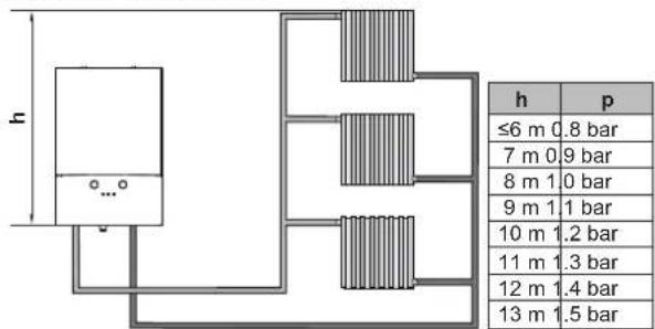
h System water height (m) p System charge pressure (bar)
According to the graph below, there is no need to install an additional expansion vessel for the systems with a water volume in the area below the operating temperature curve. If water volume is above the curve, additional vessel must be installed, preferably on the return to the boiler.
A (I)
line
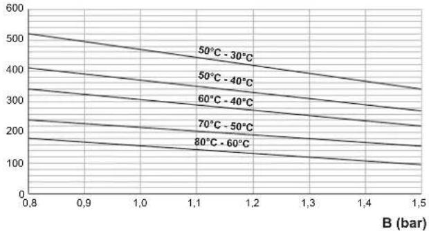
| B (bar) | 50°C - 30°C | 50°C - 40°C | 60°C - 40°C | 70°C - 50°C | 80°C - 60°C | | ------- | ----------- | ----------- | ----------- | ----------- | ----------- | | 0.8 | 520 | 410 | 330 | 230 | 180 | | 0.9 | 500 | 390 | 310 | 210 | 170 | | 1.0 | 480 | 370 | 290 | 200 | 160 | | 1.1 | 460 | 350 | 270 | 190 | 150 | | 1.2 | 440 | 330 | 250 | 180 | 140 | | 1.3 | 420 | 310 | 230 | 170 | 130 | | 1.4 | 400 | 290 | 210 | 160 | 120 | | 1.5 | 380 | 270 | 190 | 150 | 110 |A System water volume (I)
B System charge pressure (bar)
* 50°C-40°C temperature regime is given for underfloor heating systems
Water treatment
Inappropriate central heating circuit water reduces functionality and efficiency of the boiler over time. Appropriate water should have:
- pH degree between 6.5 and 8.5
- Hardness less than 15^ and 8.4^
Appropriate additives can be used for water treatment.
If antifreeze is needed for the system, the chosen antifreeze should not interact with rubber, commercial plastic and metal parts of the boiler that are in contact with the central heating water.
For use of any additive in the central heating system, please refer to the instructions of their manufacturers to ensure above functionality and compatibility.

WARNING
Mixing inappropriate additives with the central heating circuit water can result in efficiency loss in the boiler or damage to the boiler and the other central heating circuit elements. Daikin accepts no liability for any such damage or ineffectiveness caused by using inappropriate additive.
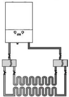
4.6 Underfloor heating requirements
Underfloor heating systems apparently require higher flow rate and lower T . This boiler can be connected to an underfloor heating system without use of a second pump and low loss header because of its high pump capacity. Direct connection is possible when the system is well designed and pressure loss is low enough.
natural_image
Pure electrical circuit lines without any symbolsWhen the boiler is connected to underfloor heating installation, the maximum central heating set temperature must be limited to 50°C and the pump operation temperature difference must be adjusted to 10 Kelvin in the service settings menu. To change this setting, refer to the servicing instructions.

WARNING
Make sure parameter changes explained above are done to avoid discomfort of the user.
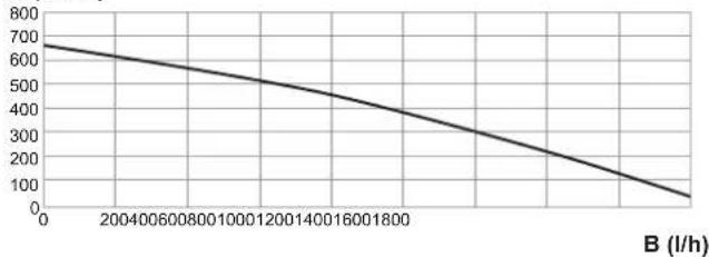
4.7 Residual pump lift graph
The residual pump lift graph shows the amount of pump lift (mbar) that remains for the central heating circuit.
A (mbar)
line
| X-axis (l/h) | Y-axis (l/h) | |---|---| | 0 | 680 | | 200400 | 630 | | 0600800 | 590 | | 1000120 | 550 | | 12001400 | 510 | | 14001600 | 470 | | 1800 | 430 | | 2400 | 380 | | 3200 | 330 | | 4000 | 280 | | 4800 | 230 | | 5600 | 180 | | 6400 | 130 | | 7200 | 90 | B (l/h)A Residual pump lift (mbar)
B Flow (l/h)
4.8 Connections

NOTICE
During installation, do not loosen or remove any screw from bottom plate.
4.8.1 Piping connections
Piping connections of model D2C20ND028A5AA and D2C24ND035A5AA
Below, find the piping connections of the unit.
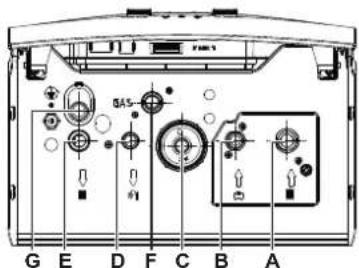
A Central heating return connection, 3/4"
B Domestic cold water inlet connection, 1/2"
C Condensate trap discharge
D Domestic hot water outlet connection, 1/2"
E Central heating supply connection, 3/4"
F Gas inlet connection, 3/4"
G Safety valve discharge
E
F
B
natural_image
Pure mechanical assembly diagram without any text, numbers, or symbols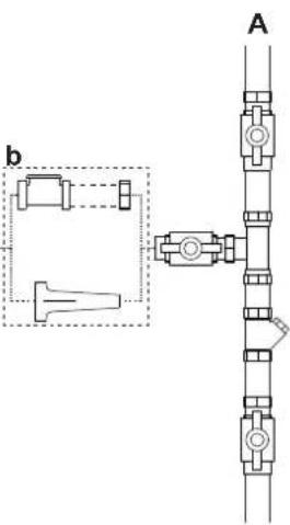
natural_image
Pure mechanical assembly diagram with no text, numbers, or symbols
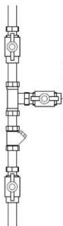
Valve
Strainer
Tee connection

Double check valve + filling hose
Disconnector
a Isolation valve on domestic hot water supply pipe is tentative.
b External filling group used with model D2C20ND028A5AA andD2C24ND035A5AA. Use a disconnector or a double check valve according to local regulations.
Isolation valves and strainers should be used just before the appliance piping inlet as shown in figure above.
Ensure that necessary gaskets are placed.
Note: Optional Daikin connection kit can be used and it is recommended to use it.
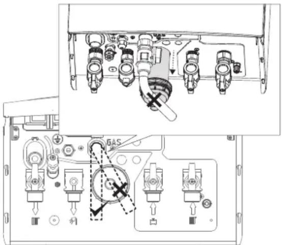
4.8.2 Guidelines when connecting the gas piping
This unit is designed to be operated with natural gas or LPG. The preset gas type and the designated gas inlet pressure are indicated on the boiler's identification label.

WARNING
Only qualified persons are allowed to connect the gas piping. The gas inlet pipe diameter must be selected according to the applicable legislation, standards, and regulations.
Connect the gas piping according to applicable legislation of the country of destination and the regulations of the gas supply company.
Connect the gas supply piping without tension to the gas pipe connection ("Connection F", see "4.8.1 Piping connections" on page 11).

WARNING
After the gas connection is made, the gas line must be tested for leakage while the gas line to the boiler is open (see "5.3 To check for gas leakage" on page 24).
In case gas piping is adjacent to the wall and is to be connected to the gas pipe connection of the boiler with an elbow, enough space for taking out the condensate trap must be left. This can be done in two ways:
1 Elbow must be placed crosswise so it will not block the condensate trap when it is being taken out.
2 Elbow must be placed 200 mm below the gas piping connection of the boiler.
4.8.3 Guidelines when connecting the water piping
When connecting the piping to the boiler, observe the following instructions:

WARNING
Ignoring the rules explained below may result in serious damages in installation or boiler or cause discomfort of the user. The manufacturer is not responsible for any damage that may occur this way.
- The installation of the boiler should be in compliance with the applicable legislation, standards, and regulations.
- The materials used in the installation must be in compliance with the applicable legislation, standards, and regulations.
-
Heating installation piping material must not allow oxygen diffusion according to DIN4726.
-
The central heating/domestic hot water installation should be flushed and visually inspected. Wastes, dust, rubbers, and metal pieces generated during the installation and mounting of the boiler must be removed in order not to cause any damage.
- The central heating circuit must be able to withstand a pressure of at least 6 bar.
- Cross connection must be preferred in the radiators longer than 1.5 metres.
- The safety valve piping should be connected to a water outlet with an additional hose or piping. This outlet should not be installed in places where there is risk of freezing, nor in the rain gutter, it should not end to dry floor without available drainage to avoid damaging of floor coating like parquet.
- The maximum pressure in the domestic hot water circuit is 10 bar. Inspect the piping taking this in to consideration. If the water pressure of the main water supply is excessive, use an appropriate pressure reducer. Installation must comply with EN 15502-2-2.
- As the condensing boilers generate condensate, the condensate trap outlet should be connected to an open drain. Piping and elements of the drain line must be made of acid-resistant material like plastics. Metals like steel or copper are not allowed.
- The system must be air-free to protect the boiler. There are two automatic air vents on the boiler, one at heat exchanger, the other on the pump. Ensure air is discharged completely at each water filling. Bleed the radiators if necessary.
- If the boiler will be connected to an old central heating/domestic hot water installation, then first visually inspect the old installation. The installation must be in compliance with the capacity of the boiler and must not prevent the efficient running of it. Dirt in old system and piping must be flushed, and filters must be inspected.
- If old piping material does not have oxygen barrier, then it must be separated from the boiler circuit via a plate heat exchanger and a second pump has to be installed for necessary circulation.
- If the pressure reading on the boiler user interface is dropping repeatedly, most probably there is a leakage in the installation. Inspect the installation to repair.
- In case of solar preheating of the domestic hot water from a solar tank, install the thermostatic mixing valve at the domestic hot water outlet and inlet.
4.8.4 Guidelines when connecting the electrical wiring

DANGER
Before working on the electrical circuit always isolate the unit from the power mains.

WARNING
Only qualified persons are allowed to make electrical connections on the unit. Failure to observe this warning will void the warranty. The manufacturer is not responsible for any damage that may occur this way.

WARNING
Use a dedicated power circuit. Never use a power supply cable shared by another unit.
The unit runs on 230 V AC 50 Hz power. A power cable is delivered with the package. The power cable must be connected to the power supply by an electrician and in accordance with the applicable legislation.
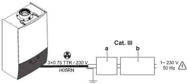
a Safety breaker (2 A)
b Earth leakage safety breaker
Cat. III Overvoltage category III
- Electrical work should be carried out in accordance with the installation manual and the national electrical wiring rules or code of practice.
- Insufficient capacity or incomplete electrical work may cause electrical shock or fire.
- A main switch or other means for disconnection, having a contact separation in all poles providing full disconnection under overvoltage category III, shall be installed in the fixed wiring.
- Be sure to establish an earth. Do not earth the unit to a utility pipe, lightning arrester, or telephone earth. Incomplete earth may cause electrical shock and fire.
- While the electrical connections are being done, energy should not be on the main power supply cable and the main switch should be closed.
- During the electrical connections, make sure that the cables are well-fixed and are connected firmly and tightly.
- Power supply cable must be equivalent to H05RN-F (2451EC57) as minimum requirement.
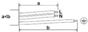
Observe the point mentioned below when wiring to the power supply terminal board.
- Wall-mounted condensing boiler
- Table of contents
- Introduction 3
- Safety instructions 4
- About the unit 4
- Installation 8
- Commissioning 24
- Hand-over to the user
- Disposal
- Introduction
- About the documentation
- Meaning of warnings and symbols
- DANGER
- WARNING
- CAUTION
- NOTICE
- INFORMATION
- Identification label
- Symbols on the package
- Safety instructions
- About the unit
- Safety systems
- High pressure protection:
- Dimensions
- Components
- Technical specifications
- Installation
- To open the unit
- Installation site requirements
- To unpack the unit
- To mount the unit
- Central heating system requirements
- Expansion vessel sizing
- Water treatment
- Underfloor heating requirements
- Residual pump lift graph
- Connections
- Piping connections
- Guidelines when connecting the gas piping
- Guidelines when connecting the water piping
- Guidelines when connecting the electrical wiring
Brand : DAIKIN
Model : D2HND012
Category : Boiler