F100F2010U - Air purifier HONEYWELL - Free user manual and instructions
Find the device manual for free F100F2010U HONEYWELL in PDF.
Download the instructions for your Air purifier in PDF format for free! Find your manual F100F2010U - HONEYWELL and take your electronic device back in hand. On this page are published all the documents necessary for the use of your device. F100F2010U by HONEYWELL.
USER MANUAL F100F2010U HONEYWELL
GETTING STARTED MOUNTING
INCLUDED IN THIS BOX
68-0239EF-13 Tools needed to install Enhanced Air Cleaner
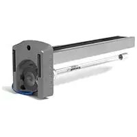
Media Air CleanersGETTING STARTED Congratulations for selecting the Media Air Cleaner for your home comfort system! The Media Air Cleaner captures and removes a signicant amount of the air-borne particles from the air circulated through the high-efciency pleated media lter. The Media Air Cleaner easily mounts in any position within the return air duct of any gas, oil, and electric forced warm air furnaces and to compressor cooling up to 5 tons. Additionally, it requires no electrical connections or maintainence beyond periodic media lter replacement. When Installing this Product...
1. Read these instructions carefully. Failure to follow them could damage the product or cause a hazardous condition.
Check the rating given in the ins tructions and on the product to make sure the product is suitable for your application.
Ins taller must be a trained, experienced service technician.
4. After installation is complete, check out product operation as provided in these instructions.
How it Works The lter in your Media Air Cleaner is made up of a web of bers. As air passes through the Media Air Cleaner, particulates such as dust, pollen, dander, mold, and bacteria collide with the bers in the lter and become trapped. Meanwhile, the clean air is allowed to continue through your heating and cooling system and into your home. The particle removal efciency of the Media Air Cleaner can be found in the Specication section of this manual. What to Expect From Your Media Air Cleaner Application Considerations The Media Air Cleaner is designed to work with gas, oil, and electric forced warm air furnaces and with compressor cooling. It can also be used with heat pumps if the lter is changed regularly to prevent excessive pressure drop. The Media Air Cleaner is not recommended for applications where pressure drop may be critical. Models F100F Media Air Cleaner includes cabinet, access door and MERV 11 pleated media lter. F200F Media Air Cleaner includes cabinet, access door and MERV 13 pleated media lter. Air Conditioning Mount the media air cleaner upstream of the evaporator coil in a cooling system. The lter will help to keep the coil clean and reduce maintenance. Humidiers The media air cleaner is compatible with humidiers. Avoid applications where water mist will reach the media. If an atomizing humidier is used, the media lter will require replacement more often because of minerals in the water. UV Lights Germicidal UV lights can cause degradation of the media lter. The UV light should be located out of line of sight or a minimum of 3 feet from the lter. Otherwise the lter may need to be replaced more frequently. Media Air Cleaner 68-0239EF—13 2GETTING STARTED Transitions For most efcient air cleaning, spread airow evenly across the face of the media. If the duct is a different size than the media air lter cabinet, gradual transitions are required. Follow these guidelines when fabricating:
- Use gradual transitions to reduce air turbulence and increase efciency.
- Use no more than 20 degrees (about 4 in. per running ft. [100 mm per 300 linear mm]) of expansion on each side of a transition tting. Turning Vanes If the media air cleaner is installed next to an elbow or angle tting, add turning vanes inside the angle to distribute airow more evenly across the face of the media. See middle gure. Sheetmetal The media air cleaner is adaptable to all new or existing forced air heating and cooling systems used in residential applications. Transitions or turning vanes may be required in some applications for effective media air cleaner operation. Offsets If the duct connection to the furnace in a side installation allows less than 7 in. (178 mm) for mounting media air cleaner cabinet, attach an offset to the elbow. See bottom gure at right. TURNINGVANES M5651 M948C LESS THAN 7 in.(178 mm)OFFSETAT LEAST7 in.(178 mm) 1 REQUIRED TURNING VANES HELP DISTRIBUTE AIRFLOW EVENLY.20 DEGREE EXPANSION PER SIDE PER FITTING (4 IN. PER RUNNING FOOT [100 MM PER 300 LINEAR MM]) RETURN AIR DUCT TRANSITION FITTING ELECTRONIC AIR CLEANER CABINETM947B DUCT SIZE CHANGED GRADUALLY TO PREVENT TURBULENCE. Media Air Cleaner 68-0239EF—13 3GETTING STARTED Important Installation Requirements Personal Safety
- Wear safety glasses while installing the unit.
- Do not cut into any air conditioning or electrical line.
- Follow professional safety standards and all local codes for plumbing, electrical, and mechanical considerations. Before Mounting
- Using the gure on the cover and the lists on the inside cover, make sure that you have all the components for your Media Air Cleaner and the tools to install it.
- Ensure airow direction through the Media Air Cleaner matches the arrows on the lter cartridge. The arrows should point in the direction of the airow.
- Choose a location that is readily accessible for checking and replacing the lter. Allow at least 26 in. (660mm) clearance in front of the unit for removal of the cartridge.
- Install the media air lter where the temperature will not exceed the ratings in the Specications.
- Do not mount in the supply air duct. NOTE: Generally , the best location is in the return air duct next to the blower compartment so the media air cleaner can help to keep the blower motor and evaporator coils clean. If Replacing an Old Air Cleaner If the Media Air Cleaner is not identical in size and shape to the existing air cleaner, before performing a retrot installation, you might need to add duct transitions to ensure a smooth air ow. For optimum system performance, replace the lter every six months (before heating season and before cooling season). Adjust the schedule to your needs, but replace the lter at least once per year. Failure to comply with these requirements will result in voided warranty, improper installation, and service callbacks. Media Air Cleaner 68-0239EF—13 4MOUNTING The Media Air Cleaner mounts in any position within the return air duct, usually next to the furnace blower compartment, but the arrow on the cartridge must point in the same direction as the airow. See Figs. 1-8 for proper location of the media air cleaner for a variety of furnace installations. NOTE: The media air cleaner cabinet is s turdy enough to easily support the weight of the furnace and evaporator coil. M939C M940C Choosing a Mounting Position Before beginning Mounting: I have chosen an installation location that meets the requirements on pages 5 through 6. Fig. 1. Highboy furnace with side installation. Media air lter is mounted vertically where return enters side inlet of furnace. Fig 2. Highboy furnace, with installation beneath furnace. Media air cleaner is mounted horizontally where return enters from below. M941A Fig. 3. Highboy furnace, with closet installation. Media air cleaner is mounted vertically on furnace between furnace and louvered return air opening in closet door. Media Air Cleaner 68-0239EF—13 5MOUNTING M942C Fig. 4. Lowboy furnace, with media air cleaner mounted horizontally in return plenum just above furnace and opposite heating plenum. M943C M944C Fig. 5. Counterow furnace, with media air cleaner mounted horizontally in return duct or plenum just above furnace. Fig. 6. Central fan installation, with media air cleaner mounted horizontally in central return duct. M945C M946C Fig. 7. Horizontal furnace, with media air lter mounted vertically in return duct near furnace. Fig. 8. Two or more media air cleaners used in a high capacity system. Media Air Cleaner 68-0239EF—13 6MOUNTING The following procedure describes a typical side installation on an existing highboy furnace (Fig. 1). Alternate procedures are noted as appropriate. Other changes in installation procedures may be necessary to complete your installation. NOTE: Bef ore starting the installation, remove and discard the existing furnace lter (if used). Thoroughly clean the blower compartment. If possible, power vacuum the ductwork to remove accumulated dust in an occupied home or remove construction dirt in a new home. The media air cleaner cannot remove dirt that has settled in the blower compartment and distribution ducts. STEP ONE: Review the Installation Plan Temporarily place the cabinet on the oor, oriented as it will be when installed. Insert and remove the cartridge to make sure the plan allows adequate clearance for easy removal and replacement of the cartridge. STEP TWO: Fasten the Cabinet to the Furnace a. Align the cabinet with the return air opening. b. Place blocks under the cabinet, as necessary, to make sure the unit sits securely. c. Create an opening in the furnace to match the cabinet opening. d. Attach the cabinet securely to the furnace. Attach the unit directly or t a starting collar in the furnace opening. Either drill holes and fasten with sheetmetal screws or rivets, or use slip joints. If you are drilling holes, use a locking pliers to help hold the unit in place during drilling. STEP THREE: Install Turning Vanes Install turning vanes to help distribute air equally over the full surface of the upstream side of the media. Install them whenever an abrupt 90 degree elbow is installed directly against the media air cleaner cabinet. STEP FOUR: Fasten Cabinet to Ductwork Fasten side of cabinet to the ductwork using sheet-metal screws, rivets, or slip joints, as appropriate. STEP FIVE: Connect Ductwork a. Connect the vertical duct section to the elbow. If the vertical drop of the duct is less than 7 in. (178 mm) from the side of the furnace, shorten the horizontal trunk or attach an offset tting to the elbow. b. When ductwork is properly aligned, connect the vertical duct to the horizontal trunk. STEP SIX: Seal Joints Seal all joints in the return air system between the media air lter and the furnace to prevent dust from entering the clean airstream. STEP SEVEN: Install Filter Cartridge Slide the lter cartridge into the cabinet, making sure the arrow on the cartridge points in the direction of air ow. Replace access door. Insert the tab on the bottom of the door into the slot in the cabinet. Swing the door closed and press it into place. Mounting the Media Air Cleaner Media Air Cleaner 68-0239EF—13 7MOUNTING Visually check the installation and make sure that:
- Airflow is in the direction of the arrow on the media air filter cartridge.
- Turning vanes and transitions, if used, are properly installed.
- Joints in sheetmetal between media air filter and furnace are sealed.
- All sheetmetal connections are complete.
- Original furnace filter has been removed and blower compartment is cleaned. When you have veried that checkout has been completed:
- Replace any access doors removed during the Installation or Checkout.
- Run the furnace or cooling system through one complete cycle to make sure the system operates as desired. The media lter must be replaced when pressure drop across the media lter reaches 0.5 in. w.c. (0.1 kPa), or at least annually. If the media air cleaner is installed downstream from an atomizing humidier or if the installation includes both heating and cooling, more frequent replacement may be necessary. Clogged media must be replaced promptly to avoid restricting airow and reducing efciency of the heating/cooling system. Record the replacement date in the space provided on the replacement media lter. Checkout Maintenance Specications The specications in this publication do not include normal manufacturing tolerances; therefore, an individual unit may not exactly match the listed specications. This product is tested and calibrated under closely controlled conditions, and some minor differences in performance can be expected if those conditions are changed. Media Air Cleaner 68-0239EF—13 8SPECIFICATIONS F100 Specications MERV Rating*: MERV 11 Static Pressure Drop: 0.23 (in. w.c.) at 500 FPM Efciency Denition*: Small Particles: E1 = 0.3 to 1.0 microns = 32% Medium Particles: E2 = 1.0 to 3.0 microns = 72% Large Particles: E3 = 3.0 to 10.0 microns = 96%
F200 Specications MERV Rating*: MERV 13 Static Pressure Drop: 0.3 (in. w.c.) at 500 FPM Efciency Denition*: Small Particles: E1 = 0.3 to 1.0 microns = 63% Medium Particles: E2 = 1.0 to 3.0 microns = 91% Large Particles: E3 = 3.0 to 10.0 microns = 99%
DIM. B16-1/416-1/420-3/1620-3/1625-3/1625-3/16
BLE) Dimensions Temperature Rating -40° to +140°F (-40° to +60°C) Approvals Underwriters Laboratories, Inc.: Listed to UL 900, Class 2.
Minimum Efciency Repor ting Value (Media Filters Only)
Efciency ratings are based on American S ociety of Heating, Refrigerating and Air-Conditioning Engineers Standard 52.2-1999. Replacement Air Filters Filter Size (in.) Part Number
25 x 20 FC100A1037 FC200E1037 25 x 22 FC100A1037 FC200E1037 Media Air Cleaner 68-0239EF—13 9Resideo Inc., 1985 Douglas Drive North Golden Valley, MN 55422 www.resideo.com This product is manufactured by Resideo Technologies, Inc., Golden Valley, MN, 1-800-468-1502 © 2019 Resideo Technologies, Inc. The Honeywell Home trademark is used under license from Honeywell International Inc. All rights reserved. 68-0239EF—13 M.S. Rev. 11-19 | Printed in United StatesPOUR COMMENCER MONTAGE CARACTÉRISTIQUES TECHNIQUES
DIM. B16-1/416-1/420-3/1620-3/1625-3/1625-3/16