25iM - Ice machine Marvel - Free user manual and instructions
Find the device manual for free 25iM Marvel in PDF.

User questions about 25iM Marvel
0 question about this device. Answer the ones you know or ask your own.
Ask a new question about this device
Download the instructions for your Ice machine in PDF format for free! Find your manual 25iM - Marvel and take your electronic device back in hand. On this page are published all the documents necessary for the use of your device. 25iM by Marvel.
USER MANUAL 25iM Marvel
Unpacking your ice machine.... 3
Removing interior packaging.... 3
Warranty Registration.... 3
Installing your ice machine.... 4
Selecting the location.... 4
Outdoor Installation 4
Winterizing 4
Cabinet Clearances.... 4
Leveling legs.... 5
Electrical Connection 5
Connecting the water supply.... 6
Using your ice machine.... 7
Turning on your ice machine.... 7
Ice machine operation.... 7
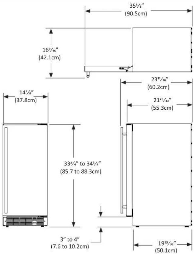
Dimensions For 15iM Solid Door.... 8
Recommended Rough in Opening Dimensions
For 15iM Solid Door....8
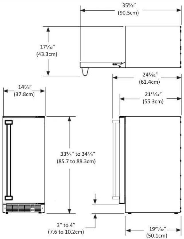
Dimensions For 25iM Solid Door....9
Recommended Rough in Opening Dimensions
For 25iM Solid Door....9
Dimensions For 25OiM Solid Door.... 10
Recommended Rough in Opening Dimensions
For 25OiM Solid Door.... 10
Dimensions For 25iM Solid Overlay Door.... 11
Recommended Rough in Opening Dimensions
For 25iM Solid Overlay Door.... 11
Full Overlay Panel Installation Instructions.... 12
Energy Saving Tips 15
Care and Cleaning.... 15
Cabinet 15
Interior 15
Defrosting instructions.... 15
Troubleshooting Guide.... 16
Obtaining Service.... 18
Household Product Warranty.... 19
Important Safety Instructions
Warnings and safety instructions appearing in this guide are not meant to cover all possible conditions and situations that may occur. Common sense, caution, and care must be exercised when installing, maintaining, or operating this appliance.
Recognize Safety Symbols, Words, and Labels.

WARNING
WARNING-Hazards or unsafe practices with high probability of personal injury or property / product damage.

CAUTION
CAUTION-Hazards or unsafe practices which could result in personal injury or property or product damage.
NOTE
NOTE-Important information to help assure a problem free installation and operation.


AGA MARVELis committed to building a quality product in an environmentally friendly manner. Our processes are tightly controlled and closely monitored. We have achieved certifications in ISO 9001 for quality assurance, ISO 14001 for environmental management, and OHSAS 18001 for occupational health and safety from Lloyd's Register Quality Assurance.
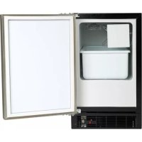
Remove Interior Packaging
Your ice machine has been packed for shipment with all parts that could be damaged by movement securely fastened. Remove internal packing materials and any tape holding internal components in place. The owners manual is shipped inside the product in a plastic bag along with the warranty registration card, and other accessory items.
Important
Keep your carton and packaging until your ice machine has been thoroughly inspected and found to be in good condition. If there is damage, the packaging will be needed as proof of damage in transit. Afterwards please dispose of all items responsibly in particular the plastic bags which can be a suffocation hazard.
Note to Customer
This merchandise was carefully packed and thoroughly inspected before leaving our plant. Responsibility for its safe delivery was assumed by the retailer upon acceptance of the shipment. Claims for loss or damage sustained in transit must be made to the retailer.
DO NOT RETURN DAMAGED MERCHANDISE TO THE MANUFACTURER - FILE THE CLAIM WITH THE RETAILER.

CAUTION
If the unit was shipped or has been laying on its back for any period of time allow the ice machine to sit upright for a period of at least 24 hours before plugging in. This will assure oil returns to the compressor. Plugging the ice machine in immediately may cause damage to internal parts.
Warranty Registration
It is important you send in your warranty registration card immediately after taking delivery of your ice machine.
The following information will be required when registering your unit.
Model Number
Serial Number
Date of Purchase
Dealer's name and address
The model number and serial number can be found on the serial plate which is located on the bottom face inside the cabinet. See figure 1.
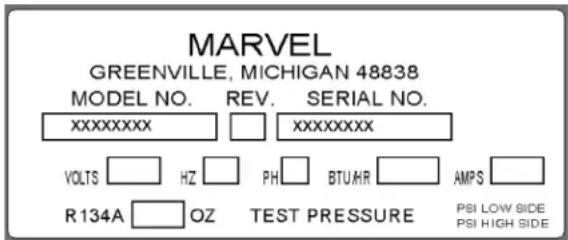
Figure 1

CAUTION
Help Prevent Tragedies
Child entrapment and suffocation are not problems of the past. Junked or abandoned refrigerators are still dangerous - even if they sit out for “just a few days”.
If you are getting rid of your old refrigerator, please follow the instructions below to help prevent accidents.
Before you throw away your old refrigerator or freezer:
• Take off the doors or remove the drawers.
- Leave the shelves in place so children may not easily climb inside.
Select Location
The proper location will ensure peak performance of your appliance. We recommend a location where the unit will be out of direct sunlight and away from heat sources. To assure your product performs to specifications the recommended installation location temperature range is from 65 to 90°F (18 to 32°C).

CAUTION
Outdoor Installation
Only the 25OiM model is suitable for outdoor installations.
Building codes may require a ground fault circuit interrupter electrical receptacle to supply electrical power to the refrigerator for outdoor applications, (see "Electrical Connection" section).
Do not install in a location where the unit will be exposed to direct sun exposure as this may result in unsatisfactory performance.
Winterizing your Outdoor Ice Maker
In colder climates the ice maker will need to be winterized. The water fill valve needs to be disconnected from the water supply line. The water fill line from the bottom of the water fill valve will also need to be disconnected and drained.
With the fill valve disconnected and the fill line drained, leave the ice maker running and allow the unit to dump one last time to remove any ice from the trays.
If the unit is to be sitting for a prolonged period of time not running, it is advisable to dry out the tray with paper towels.
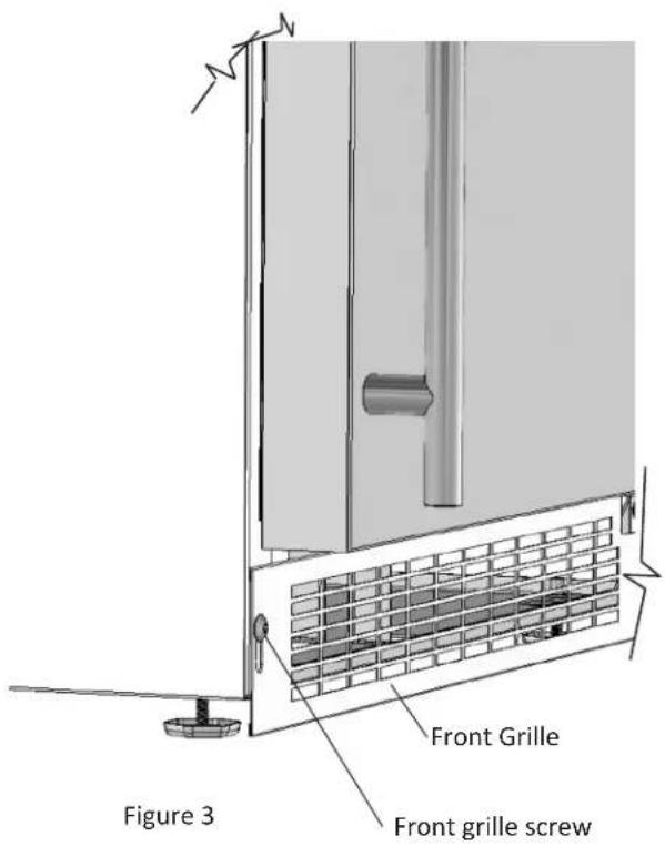
Cabinet Clearance
Ventilation is required from the bottom front section of the unit. Keep this area open and clear of any obstructions. Adjacent cabinets and counter top can be installed around the unit as long as the front grille remains unobstructed.

CAUTION
Front Grille
Do not obstruct the front grille. The openings within the front grille allow air to flow through the condenser heat exchanger. Restrictions to this air flow will result in increased energy usage and loss of cooling capacity. For this reason it is important this area to not be obstructed and the grille openings kept clean. AGA MARVEL does not recommend the use of custom made grilles as air flow may be restricted because of inadequate openings. (See Figure 2).
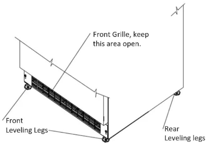
Figure 2
Leveling Legs
Adjustable legs at the front and rear corners of the unit should be set so the unit is firmly positioned on the floor and level from side to side and front to back. The overall height of your Marvel refrigerator, depending on the model, may be adjusted from 24 ^1/8 " (61.3cm) or 33 ^3/4 " (85.7cm) with the leveling legs turned in, and up to 25 ^1/8 " (63.8cm) or 34 ^3/4 " (88.3cm) with the leveling legs extended.
To adjust the leveling legs, place the refrigerator on a solid surface and protect the floor beneath the legs to avoid scratching the floor. With the assistance of another person, lean the refrigerator back to access the front leveling legs. Raise or lower the legs to the required dimension by turning the legs. Repeat this process for the rear by tilting the refrigerator forward using caution to prevent the door from opening. On a level surface check the refrigerator for levelness and adjust accordingly.
The front grille screws may be loosened and the front grille adjusted to the desired height. When adjustment is complete tighten the two front grille screws. (See Figure 3).

CAUTION
- Do not splash or spray water from a hose on the ice machine! Doing so may cause an electrical shock, which may result in severe injury or death.
- This unit should not, under any circumstances, be installed to an un-grounded electrical supply.
Electrical Connection
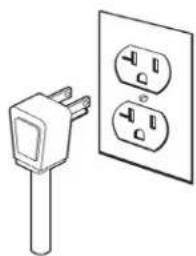
A grounded 115 volt, 15 amp dedicated circuit is required.
This product is factory equipped with a power supply cord that has a three-pronged, grounded plug. It must be plugged into a mating grounding type receptacle in accordance with the National Electrical Code and applicable local codes and ordinances (see Figure 4). If the circuit does not have a grounding type receptacle, it is the responsibility and obligation of the customer to provide the proper power supply. The third ground prong should not, under any circumstances, be cut or removed.

CAUTION
Electrical Extension cords should not be used. They can be hazard-
ous and cause deficient operation. The wall receptacle should be located near the product and be a polarized type with adequate ground protection. The product must be installed to your local building codes and ordinances.
natural_image
Simple line drawing of an electrical plug and two socket (no text or symbols)Figure 4
NOTE
Ground Fault Circuit Interrupters (GFCI) are prone to nuisance tripping which will cause the unit to shut down. GFCI's are generally not used on circuits with power equipment that must run unattended for long periods of time, unless required to meet local building codes and ordinances.
Water Supply

CAUTION
Observe and follow all local building codes when installing this appliance.
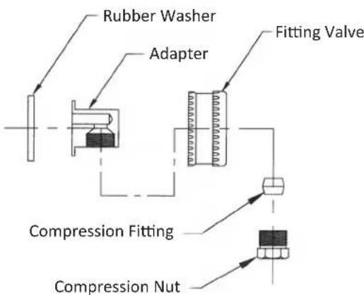
Attach the supplied water line adapter (Figure 6) to the water valve inlet on the back of the ice machine (See Figure 5). Be sure the rubber washer is in place in the inlet valve nut. Bend the 1/4'' copper tubing to suit your installation being sure not to kink the tubing. Use 1/4'' copper tubing for your water supply which is available at any local hardware or plumbing supply store. A shut-off valve is recommended. NOTE: DO NOT USE A SELF-PIERCING TYPE VALVE. Connect the copper tubing water supply to the copper tubing from the adapter assembly with the provided brass union. Secure the water supply line to the back of the cabinet with the screw and clamp provided in the corner of the back panel. (See Figure 5).
Water pressure must be at a minimum of 20 psi for proper operation and a maximum of 120 psi.
Make certain all water connections are watertight after installation. Form the tubing so that it will not vibrate against the cabinet body or kink when your ice machine is set in position.
NOTE
- Do not use any thread sealers on these water line fittings.
- Do not use a "Reverse Osmosis" Filtering Device.
- Softened water is not recommended. This will produce soft cloudy ice cubes that will stick together.
- De-ionized water is not recommended. This water will not form solid ice cubes.
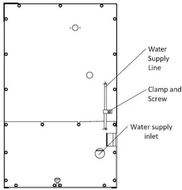
Figure 5 Back view of ice machine
flowchart
graph TD
    A["Rubber Washer"] --> B["Adapter"]
    B --> C["Fitting Valve"]
    C --> D["Compression Fitting"]
    D --> E["Compression Nut"]
    style A fill:#f9f,stroke:#333
    style B fill:#ccf,stroke:#333
    style C fill:#cfc,stroke:#333
    style D fill:#fcc,stroke:#333
    style E fill:#cff,stroke:#333
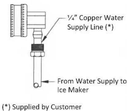
Figure 6
Turning on the ice machine
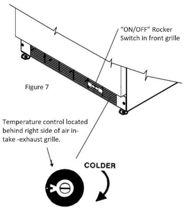
After connecting the water supply, and setting your ice machine in place plug the power cord into the wall receptacle. Then place the switch located in the grille (see Figure 7) to the "ON" position. The temperature control is factory preset, allow the ice maker to run for 24 hours so the interior temperature will stabilize. If you wish to adjust the interior temperature use a small bladed screwdriver pushed through the right hand side of the grille to turn the temperature control shaft. Turning it clockwise will make the unit colder. Turning it counterclockwise will make it warmer. Turning it counterclockwise until it stops will shut off the compressor and fan motor.

CAUTION
Should you turn off your control, allow at least five (5) minutes before restarting in order to give the motor control time to automatically reset so that it can restart the motor. Electrical power to your unit is controlled by the "ON/OFF" rocker switch located in the front grille. (See Figure 7).
Ice maker operation
- The unit must be installed level for proper ice maker operation.
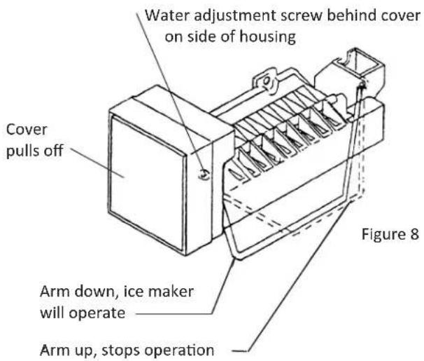
- The shutoff arm wire must be down in its lowest position for the ice maker to operate.
- When the freezer section and ice maker unit has sufficiently cooled, the ice maker will harvest ice cubes automatically.
- When the ice bucket is full, the ice maker will automatically shut off.
- You may manually stop the ice maker by raising the shut off arm to the locking position at the up most position.
When operation of the appliance is to be discontinued for any length of time, the ice cube cavity in the ice maker should be emptied and dried. The water supply and power supply should also be shut off and the ice bucket should be emptied and cleaned.
If the ice is not used regularly, it will clump together with time. For best ice results, discard ice in the bin as required and allow the ice maker to make a new fresh batch of ice.
Water Fill Adjustment
If the water fill needs to be adjusted, turning the “water adjustment screw” (see Figure 9) clockwise increases the fill amount, turning it counterclockwise decreases the fill amount. One complete revolution will affect fill by 40cc.
NOTE
Do not turn the "water adjustment screw" more than (1) 360^ revolution in either direction. Further adjustment than (1) revolution could damage the ice maker module.
RECOMMENDED ROUGH IN OPENING DIMENSIONS,15IM SOLID DOOR
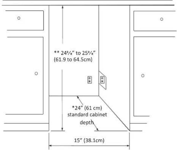

CAUTION
Electrical Requirements: A grounded 115 volt, 15 amp dedicated circuit is required.
Power outlet can be located in the back wall behind unit. Add 1" to depth for thickness of plug, or recess outlet 1" into the wall. Power outlet can also be installed in adjacent cabinetry with a cutout for routing of power cord. Follow all local building codes when installing electrical and unit. Product weight = 72 lbs. (32.7kg.)
* Depth dimension may vary depending on each individual installation.
** Minimum rough in opening required is to be larger than the adjusted height of the cabinet.
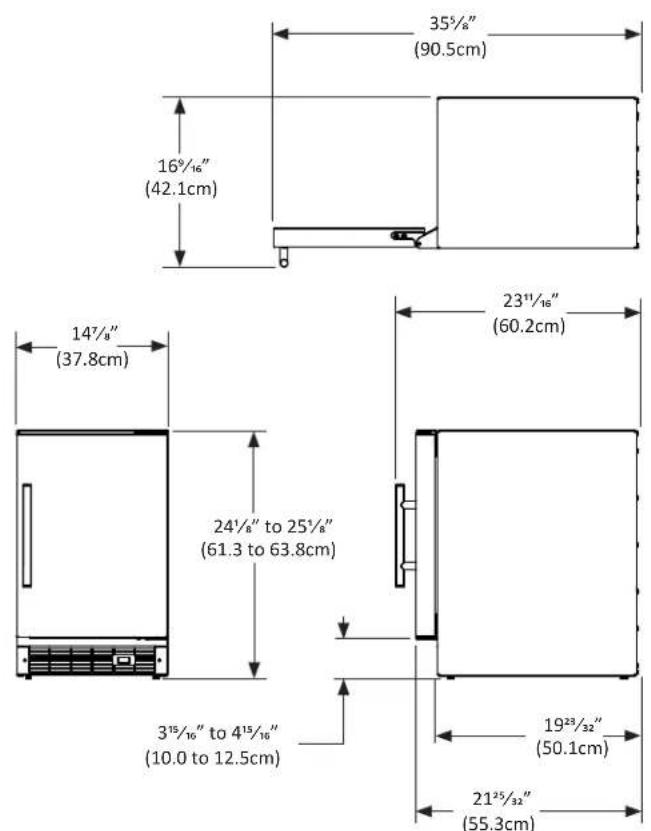
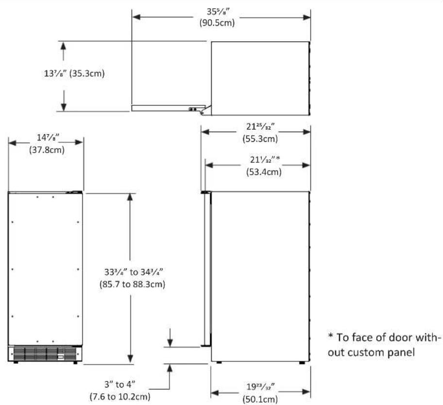
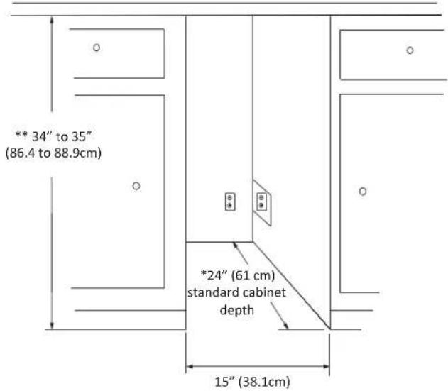
RECOMMENDED ROUGH IN OPENING DIMENSIONS, 25IM SOLID DOOR
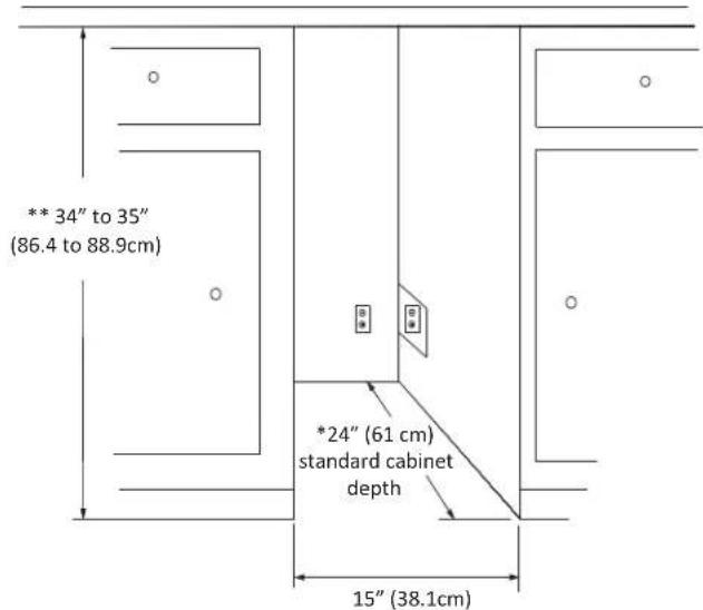

CAUTION
Electrical Requirements: A grounded 115 volt, 15 amp dedicated circuit is required.
Power outlet can be located in the back wall behind unit. Add 1" to depth for thickness of plug, or recess outlet 1" into the wall. Power outlet can also be installed in adjacent cabinetry with a cutout for routing of power cord. Follow all local building codes when installing electrical and unit. Product weight = 86 lbs. (39.1 kg.)
* Depth dimension may vary depending on each individual installation.
** Minimum rough in opening required is to be larger than the adjusted height of the cabinet.
RECOMMENDED ROUGH IN OPENING DIMENSIONS, 250IM SOLID DOOR


CAUTION
Electrical Requirements: A grounded 115 volt, 15 amp dedicated circuit is required.
Power outlet can be located in the back wall behind unit. Add 1" to depth for thickness of plug, or recess outlet 1" into the wall. Power outlet can also be installed in adjacent cabinetry with a cutout for routing of power cord. Follow all local building codes when installing electrical and unit. Product weight = 86 lbs. (39.1 kg.)
* Depth dimension may vary depending on each individual installation.
** Minimum rough in opening required is to be larger than the adjusted height of the cabinet.
RECOMMENDED ROUGH IN OPENING DIMENSIONS, 25IM SOLID OVERLAY DOOR

CAUTION
Electrical Requirements: A grounded 115 volt, 15 amp dedicated circuit is required.
Power outlet can be located in the back wall behind unit. Add 1" to depth for thickness of plug, or recess outlet 1" into the wall. Power outlet can also be installed in adjacent cabinetry with a cutout for routing of power cord. Follow all local building codes when installing electrical and unit. Product weight = 86 lbs. (39.1 kg.)
* Depth dimension may vary depending on each individual installation.
** Minimum rough in opening required is to be larger than the adjusted height of the cabinet.

CAUTION
Step 1: Verify door alignment
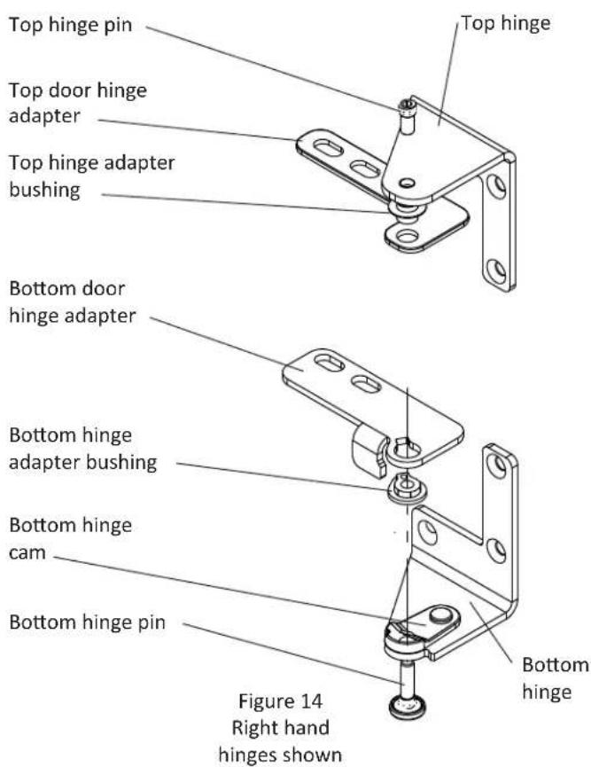
Verify that the door is aligned correctly with the cabinet prior to fabricating the custom panel. Failure to do so may result in mis-alignment of the custom panel with the hinge bracket. The door should be parallel to the sides and top of the refrigerator. If alignment is necessary the door may be adjusted by loosening the 2 screws which secure the top and/or bottom hinge adapter brackets, located on the top and bottom of the door and adjusting the door side to side. Use a 5/32'' allen wrench, for this procedure. (See Figure 9 below). When finished aligning the door, tighten the screws securely.
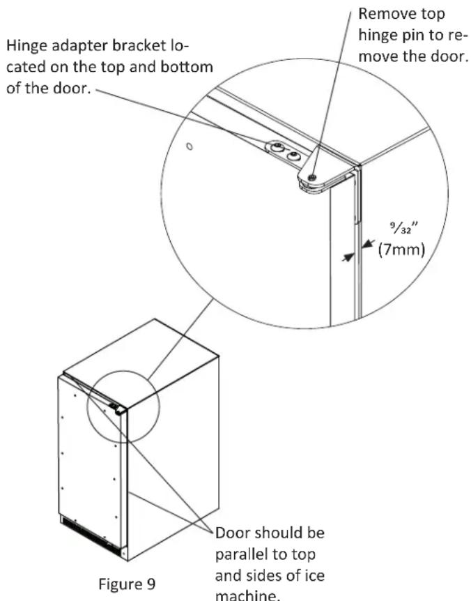
Step 2: Remove door
Remove the top hinge pin from the hinge with an 18 " allen wrench. Remove the door by angling the top of the door outward and lifting the door off the bottom hinge. (See detail in Figure 9).
Step 3: Remove gasket
Lay the door on its front being careful not to scratch it. To gain access to the screw holes remove the door gasket by peeling up and out of the channel.
Step 4: Cut overlay panel
Depending on the ice machine model cut the overlay panel to the dimensions shown in Figure 10.
NOTE
For overlay with lock option panel thickness to be 34 " (19mm) maximum to 58 " (16mm) minimum.

CAUTION
Weight of the overlay panel should not exceed 20 pounds (9.1 kilograms).
NOTE
For the door to close properly, it is necessary to maintain a minimum space of 932 " (7mm) between the door and cabinet flange (See Figure 9). This space can be adjusted by adjusting the top and bottom hinge adapter brackets.
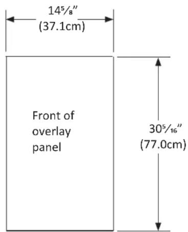
Figure 10
For model 25iM
Step 5: Drill hinge clearance holes in overlay panel
Set the overlay panel on the door front, align the edges, and clamp together. Clamp the panel firmly but be careful not to damage the door or the panel. Mark center of hinge adapter hole on wood panel, top and bottom. (See Figure 11.) Remove wood panel from door and drill 5/16'' (8mm) diameter clearance holes into the overlay panels 3/4'' (20mm) deep. These will be clearance holes for the top and bottom hinge pins.
This is also a convenient time to locate and drill the holes for your handle. Most often the handle is to match that of the surrounding cabinetry. If your handle attaches from the back-side of the custom panel, locate the mounting holes while the panel is attached to the door and cabinet. After the panel is removed from the door, drill the mounting holes from the front, to the recommended diameter of the handle manufacturer. Counter bore the back-side of the panel so the screw heads do not interfere with the surface of the door.
Step 6: Drill panel mounting holes
Re-clamp the panel to the door per step 5 and drill the screw pilot holes for attaching the overlay panel to the door. Select the size of the hole from Table A. Be careful not to drill the pilot holes through the overlay panel, (1/2" (12.7mm) deep for 3/4" (19mm) and 5/8" (15.7mm) panels).
| Material Type #8 | Wood Screw |
| Hardwood 18'' (3.2mm) Diameter. Pilot Hole | |
| Softwood 764 (2.8mm) Diameter. Pilot Hole | |
Table A
NOTE
If your ice machine has a door lock proceed to Step 7. If your ice machine does not have a door lock proceed to Step 9.
Step 7: Mark and drill lock hole.
Locate and mark with a pencil the location of the lock hole on the overlay panel, this is the hole in the top corner of the handle side of the door. Remove the clamp and remove the overlay panel from the door. On the backside of the panel where you marked the lock location drill a ^13/16 " (20.5mm) diameter counter bore ^7/16 " (11.0mm) deep into the overlay panel. Drill a ^15/_32 " (12.0mm) diameter hole through the overlay panel centered on the counter bore being careful not to splinter the wood on the face side of the panel. (See Figure 13).
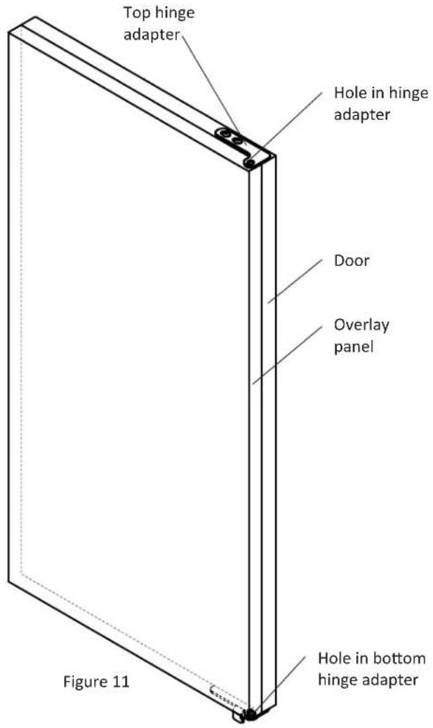
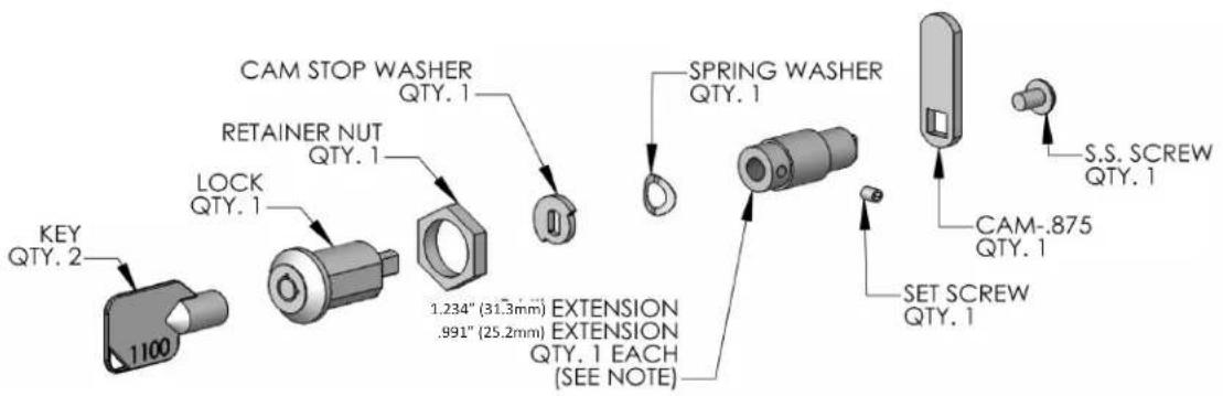
Figure 12
Step 8: Assemble the lock parts
Two (2) lock extensions are supplied with the lock. Use the longer extension for a 34 " thick overlay panel and the shorter one for a 58 " thick panel. Assemble the lock extension, cam stop washer, spring washer, and set screw to the lock as shown in Figure 12 and 13.
Install this assembly into the overlay panel and secure with the retaining nut using a 15mm socket. Make sure the key slot in the lock is vertical.
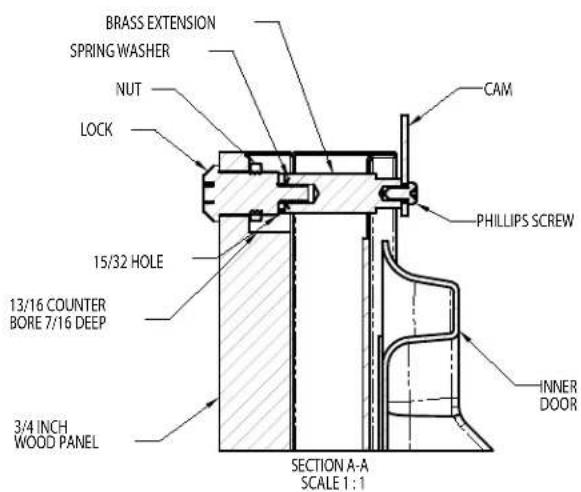
Figure 13
Step 9: Secure overlay panel to the door.
With the #10 wood screws provided, fasten the overlay panel to the door. (See Figure 15).
Step 10: Install lock cam (Models with locks only).
Attach the lock cam to the back of the lock assembly with the phillips head machine screw provided. Orient the lock cam vertically when installing on the lock.
Press the door gasket into the door channel. Make certain the gasket corners are fully inserted. If applicable insert the key into the lock and make certain the lock operates properly.
Step 12: Install the door
Install the top and bottom hinge adapter bushings back into the hinge adapters that were removed in step 6. Install the door by reversing the procedure from step 2. Install the top hinge pin so the screw head is flush with the top surface of the hinge. If applicable insert key into lock and verify the lock cam works properly with the catch bracket on the front of the ice machine cabinet.
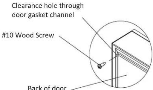
Figure 15
Cabinet
The painted cabinet can be washed with either a mild soap and water and thoroughly rinsed with clear water. NEVER use abrasive scouring cleaners.
Interior
Wash interior compartment with mild soap and water. Do NOT use an abrasive cleaner, solvent, polish cleaner or undiluted detergent.
Care of Unit
- Avoid leaning on the door, you may bend the door hinges or tip the unit.
- Exercise caution when sweeping, vacuuming or mopping near the front of the unit. Damage to the grille can occur.
- Periodically clean the interior of the unit as needed.
- Periodically check and/or clean the front grille as needed.
Defrosting Instructions
- Push the rocker switch located in the front grille to the "OFF" position.
- Remove the ice bucket and place a towel in the lower front area of the ice maker to absorb the defrost water.
- After defrosting is completed replace the ice bucket and press the rocker switch to the "ON" position.

WARNING
Do not use an ice pick, knife, or any type of sharp object to remove the ice. Doing so may puncture the units refrigerant system and damage it beyond repair. You may speed up defrosting by filling the ice bucket with hot water and placing it back into position.
ENERGY SAVING TIPS
The following suggestions will minimize the cost of operating your ice machine appliance.
- Do not install your appliance next to a hot appliance, (cooker, dishwasher, etc.). heating air duct, or other heat sources.
- Install product out of direct sunlight.
- Assure the front grille vents at front of unit beneath door is not obstructed and kept clean to allow ventilation for the refrigeration system to expel heat.
- Plug your appliance into a dedicated power circuit. (Not shared with other appliances).
- Maintaining a relatively full ice bin will require less appliance run time than an empty compartment.
- Minimize door openings and duration of door openings.
- Use the warmest temperature control set-point that meets your personal preference and provides the proper storage for your stored contents.
- When on vacation or away from home for extended periods, set the appliance to warmest acceptable temperature for the stored contents.
- Set the control to the "off" position if cleaning the unit requires the door to be open for an extended period of time.
Before You Call for Service
If the unit appears to be malfunctioning, read through this manual first. If the problem persists, check the troubleshooting guide below. Locate the problem in the guide and refer to the cause and its remedy before calling for service. The problem may be something very simple that can be solved without a service call. However, it may be required to contact your dealer or a qualified service technician.

WARNING
Electrocution Hazard - Never attempt to repair or perform maintenance on the unit until the main electrical power has been disconnected. Turning the unit control "OFF" does not remove electrical power from the units wiring.
| Problem Possible Cause Remedy | ||
| Unit operates but does not produce any ice | The unit has just been started and it has been less than 24 hours.Water supply is not turned on.Inadequate water pressure to unit.The ice maker shut off arm is in the uppermost position.Freezer section has not reached temperature.Thermostat control set too warm.Condenser fan air flow is restricted.Room and/or water temperature is too warm. | Typical ice production is 12 pounds per day. Allow for the freezer section to reach temperature and the ice maker to cycle and accumulate ice.Turn on water supply to the unit.Water pressure to the unit must be at a minimum of 20 psi.When the ice maker shut off arm is in the uppermost position, the ice maker is off. Flip the shut off arm down to turn on the ice maker.Allow the freezer section to reach temperature.Turn the temperature control to a higher number to allow the unit to run colder. Allow 24 hours before readjusting the temperature control.Make certain the grille in front of the unit is free and open for air circulation. Clean grille as required.Move the unit to an area where ambient temperature is below 90°F. The unit should not be placed next to a heat source such as an oven. Check for cold water connection. |
| Small ice cubes • Water input may require | adjustment. • Due to differing water pressures, the ice maker water input may require adjustment. See Figure 8 on page 7 for water adjustment screw location. | |
| Ice cubes are sticking together. • Ice consumption is low.Room temperature is too warm. | Use the ice in the bin frequently. Ice will stick together if left in insulated bin over long periods of time.Move the unit to an area that is below 90°F. | |
TROUBLESHOOTING YOUR ICE MACHINE
| Problem Possible Cause Remedy | ||
| Unit too warm or too cold inside. • Contro | set too warm or coldContent temperature not stabilized.Excessive usage or prolonged door openings.Airflow to front grille blocked.Door gasket not sealing properly. | Adjust temperature colder or warmer as required. Allow 24 hours for temperature to stabilize.Allow temperature to stabilize for at least 24 hours.Airflow must not be obstructed to front grille. See “clearances” on page 4.Check door alignment and/or adjust or replace door gasket.. |
| Noise or Vibration • Unit not level | Water line tubing vibration. | Level unit, see “Leveling Legs” on page 4.Adjust the tubing as necessary to eliminate unwanted vibrations. |
| Unit will not run. • Unit turned off | Power cord not plugged in.No power at outlet. | Turn unit on. See “Set the temperature control” on page 7.Plug in power cord.Check house circuit. |
| Moisture collects on outside surface of cabinet. | Hot and humid conditions. • Extremely hot and humid conditions can cause condensation on outside of the cabinet. As humidity and/or temperature decreases, the condensation will disappear. | |
| Moisture collects on inside of the unit. • Too many door openings.Prolonged door openings.Hot and humid conditions | Limit the amount of door openings.Limit the amount of time with the door open.Extreme hot and humid conditions.Move unit to a controlled environment. | |
If Service is Required:
- If the product is within the first year warranty period please contact your dealer or call AGA MARVEL Customer Service at 800.223.3900 for directions on how to obtain warranty coverage in your area.
- If the product is outside the first year warranty period, AGA MARVEL Customer Service can provide recommendations of service centers in your area. A listing of authorized service centers is also available at www.agamarvel.com under the service and support section.
- In all correspondence regarding service, be sure to give the model number, serial number, (see page 3) located on your product's serial plate, and proof of purchase.
- Try to have information or description of nature of the problem, how long the unit has been running, the room temperature, and any additional information that may be helpful in quickly solving the problem.
- Table B is provided for recording pertinent information regarding your product for future reference.
| For Your Records | |
| Date of Purchase | |
| Dealer's name | |
| Dealer's Address | |
| Dealer's City | |
| Dealer's State | |
| Dealer's Zip Code | |
| Appliance Serial Number | |
| Appliance Model Number | |
| Date Warranty Card Sent (Must be within 10 days of purchase). | |
Table B
Entire Product
Limited One Year Parts and Labor Warranty
AGA MARVEL warrants that it will supply all necessary parts and labor to repair or replace in the end user's home or office, any component which proves to be defective in material or workmanship, subject to the condition and exclusions stated below, for a period of one year from the date of purchase by the end user.
Additional Second Through Fifth Year Limited Parts Only Warranty
During the four years following expiration of the one year limited warranty, AGA MARVEL will supply replacement parts for the hermetically sealed refrigeration system which consists of the compressor, condenser, drier, accumulator, bypass valve, connecting tubing and the evaporator that are proven to be defective due to workmanship or materials subject to the conditions and exclusions below.
The above warranties do not cover:
- Shipping costs of replacement parts or returned defective parts.
- Customer education or instructions on how to use the appliance.
- Any content loss due to product failure.
- Removal or installation of product.
Nor do the above warranties cover failure of this product or its components due to:
- Transportation or subsequent damages.
- Commercial use or use other than normal household or small office.
- Improper installation, misuse, abuse, accident or alteration, use of wiring not conforming to electrical codes, low or high voltages, failure to provide necessary maintenance, or other unreasonable use.
Parts or Service
Not Supplied or Designated by AGA MARVEL
The above warranties also do not apply if:
- The original bill of sale, deliver date, or serial number cannot be verified.
- Defective parts are not returned for inspection if so requested by AGA MARVEL.
- The refrigeration equipment is not in the possession of the original end use purchaser.
The warranties set forth herein are the only warranties extended by AGA MARVEL. Any implied warranties, including the implied warranty of merchantability, are limited to the duration of these express warranties. In no event shall AGA MARVEL be liable for any consequential or incidental damages or expenses resulting from breach of these or any other warranties, whether express or implied.
Some states do not allow the exclusion or limitation of consequential damages or a limitation on how long an implied warranty lasts, so the above exclusion or limitation may not apply to you. This warranty gives you specific legal rights and you may have other rights that may vary from state to state.
No person, firm, or corporation is authorized to make any other warranty or assume any other obligation for AGA MARVEL. These warranties apply only to products used in any of the fifty states of the United States and the District of Columbia.
To obtain performance of this warranty, report any defects to:
AGA MARVEL
1260 E. VanDeinse St.
Greenville MI 48838
Phone: 800.223.3900


AGA MARVEL
1260 E. VanDeinse St.
Greenville MI 48838
800.223.3900
41011771-EN Rev R 2/13/12
www.agamarvel.com
All specifications and product designs subject to change without notice. Such revisions do not entitle the buyer to corresponding changes, improvements, additions, replacements or compensation for previously purchased products.
natural_image
Simple line drawing of an electrical outlet with two socket plugs (no text or symbols)Figure 4