USER MANUAL DW451S2 DEWALT
Definitions: Safety Alert Symbols and Words
This instruction manual uses the following safety alert symbols and words to alert you to hazardous situations and your risk of personal injury or property damage.
DANGER: Indicates an imminently hazardous situation which, if not avoided, will result in death or serious injury.
WARNING: Indicates a potentially hazardous situation which, if not avoided, could result in death or serious injury.
CAUTION: Indicates a potentially hazardous situation which, if not avoided, may result in minor or moderate injury.
(### without word) Indicates a safety related message.
NOTICE: Indicates a practice not related to personal injury which, if not avoided, may result in property damage.
Fig. A
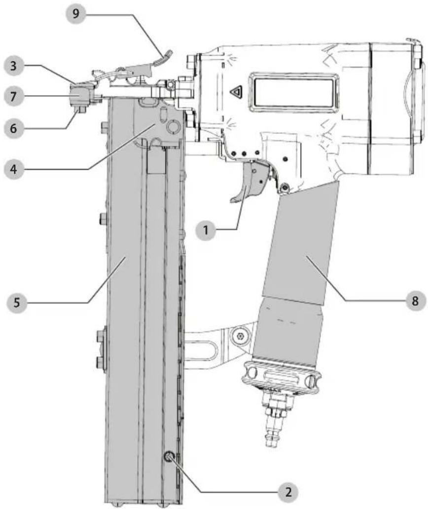
1 Trigger
2 Pusher release
3 Contact trip
4 Pusher
5 Magazine
6 Depth adjustment screw
7 Sliding shoe
8 Handle
9 Tool free jam release
WARNING: Read all safety warnings and all
instructions. Failure to follow the warnings and instructions may result in electric shock, fire and/or serious injury.

WARNING: To reduce the risk of injury, read the
instruction manual.
If you have any questions or comments about this or any DEWALT tool, call us toll free at:
1-800-4-DEWALT(1-800-433-9258).
English
IMPORTANT SAFETY INSTRUCTIONS
WARNING: Only persons who have read and understand the tool operating/safety instructions should operate the tool.
WARNING: Actuating tool may result in flying corrosion, collation material, or dust which could harm operator's eyes. Operator and others in work area MUST wear safety glasses with side shields. These safety glasses must conform to ANSI Z87.1 requirements (approved glasses have "Z87" printed or stamped on them). Employer is responsible for enforcing the usage of eye protection equipment by the tool operator and all other personnel in the work area.
WARNING: Always assume that the tool contains fasteners.
WARNING: (Air and Supply)
- Do not use oxygen, combustible gases, or bottled gases as a power source for this tool as tool may explode, possibly causing injury.
- Do not use supply sources which can potentially exceed 200 p.s.i.g. (14 kg/cm ^2 ) as tool may burst, possibly causing injury.
- The connector on the tool must not hold pressure when air supply is disconnected. If a wrong fitting is used, the tool can remain charged with air after disconnecting and thus will be able to drive a fastener even after the air line is disconnected possibly causing injury.
- Do not pull the trigger while connected to the air supply as the tool may cycle, possibly causing injury.
• Always disconnect air supply: 1.) Before making adjustments; 2.) When servicing the tool; 3.) When clearing a jam; 4.) When tool is not in use; 5.) When moving to a different work area, as accidental actuation may occur, possibly causing injury, 6.) When loading the tool.
Disconnect from air supply.
- Never place a hand or any part of body in fastener discharge area of tool.
- Never point tool at yourself or anyone else.
- Do not pull the trigger as accidental actuation may occur, possibly causing injury.
- Be careful when handling fasteners, especially when loading and unloading, as the fasteners have sharp points.
There is any damage to air hose or fitting.
• The tool leaks air.
- The tool has received a sharp blow, malfunctions or is dropped or damaged in any manner. Return tool to the nearest authorized service facility for examination, repair, or mechanical adjustment.
- Warning labels are missing or damaged.
- Tool is not in proper working order. Tags and physical segregation shall be used for control.
- Tool is without workpiece contact. A tool without workpiece contact can be fired unintentionally causing injury to an operator or a bystander.
Always handle the tool with care:
English
holstering or hanging tool, or when preparing work surface for fastening operation.
- This tool produces SPARKS during operation. NEVER use the tool near flammable substances, gases or vapors including lacquer, paint, benzine, thinner, gasoline, adhesives, mastics, glues or any other material that is -- or the vapors, fumes or byproducts of which are -- flammable, combustible or explosive. Using the fastenerer in any such environment could cause an EXPLOSION resulting in personal injury or death to user and bystanders.
• Always maintaining control of tool.
- Allowing recoil to move tool away from work surface.
- Not resisting recoil such that tool will be forced back into the work surface. In "Contact Actuation Mode," if workpiece contact is allowed to re-contact work surface before the trigger is released, an unintended discharge of a fastener will occur.
- Keeping face and body parts away from tool.
when not in use.
- When performing any maintenance or repairs,
- When clearing a jam.
- When elevating, lowering or otherwise moving tool to a new location.
- When tool is outside of the operator's supervision or control.
- When loading or removing fasteners from the magazine.
WARNING: When maintaining the tool:
Always shut off air supply, and disconnect tool from air supply when not in use.
- When working on air tools note the warnings in this manual and use extra care when evaluating problem tools.
Additional Safety Warnings
WARNING: Do not use this product to fasten electrical cables. Fastening electric wires / cables could result in electric shock or serious harm.
WARNING: Make sure there are no electrical cables, gas pipes, etc. that could cause a hazard if damaged by use of the tool.
WARNING: This tool is not intended for use in potentially explosive atmospheres and is not insulated from coming into contact with electrical power.
- Use the DEWALT pneumatic tool only for the purpose for which it was designed.
- Do not use the tool as a hammer.
• Always carry the tool by the handle with hand off trigger/ triggers.
- Never lift, pull, lower, or carry the tool by the air hose.
- Whipping hoses can cause severe injury. Always check for damaged or loose hoses or fittings.
- Never direct compressed air at yourself or anyone else.
- Compressed air can cause severe injury.
- Do not alter or modify this tool from the original design or function without approval from DEWALT.
- Never clamp or tape the trigger in an actuated position.
- Ensure tool is always safely engaged on the workpiece and cannot slip.
- Never leave a tool unattended with the air hose attached.
TO PREVENT ACCIDENTAL INJURIES:
- Never place a hand or any other part of the body in fastener discharge area of tool while the air supply is connected.
- Never actuate the tool unless nose is directed at the work.
- Do not actuate the tool while loading.
- Keep hands and body parts away from the discharge area of the tool. While in use NEVER grasp the tool by the magazine or canister, a mis-driven fastener can exit the nose causing injury.
WARNING: ALWAYS use safety glasses. Everyday eyeglasses are NOT safety glasses. Also use face or dust mask if cutting operation is dusty. ALWAYS WEAR CERTIFIED SAFETY EQUIPMENT:
• ANSI Z87.1 eye protection (CAN/CSA Z94.3),
• ANSI S12.6 (S3.19) hearing protection,
• NIOSH/OSHA/MSHA respiratory protection.
WARNING: Some dust created by power sanding, sowing, grinding, drilling, and other construction activities contains chemicals known to the State of California to cause cancer, birth defects or other reproductive harm. Some examples of these chemicals are:
- lead from lead-based paints,
• crystalline silica from bricks and cement and other masonry products, and
• arsenic and chromium from chemically-treated lumber.
Your risk from these exposures varies, depending on how often you do this type of work. To reduce your exposure to these chemicals: work in a well ventilated area, and work with approved safety equipment, such as those dust masks that are specially designed to filter out microscopic particles.
- Avoid prolonged contact with dust from power sanding, sawing, grinding, drilling, and other construction activities. Wear protective clothing and wash exposed areas with soap and water. Allowing dust to get into your mouth, eyes, or lay on the skin may promote absorption of harmful chemicals.
ENGLISH
WARNING: Use of this tool can generate and/
a adverse dust, which may cause serious and
permanent respiratory or other injury. Always use
NIOSH/OSHA approved respiratory protection
appropriate for the dust exposure. Direct particles
away from face and body.
during use. Under some conditions and duration of use, noise from this product may contribute to hearing loss.
a tripping or falling hazard. Some tools will stand upright but may be easily knocked over.
SAVE THESE INSTRUCTIONS FOR FUTURE USE
COMPONENTS (FIG. A)
WARNING: Never modify the pneumatic tool or any part of it. Damage or personal injury could result.
Refer to Figure A at the beginning of this manual for a complete list of components.
Intended Use
Your lathing stapler is designed for professional fastening applications.
DO NOT use under wet conditions or in presence of flammable liquids or gases.
This lathing stapler is a professional pneumatic tool.
DO NOT let children come into contact with the tool. Supervision is required when inexperienced operators use this tool.
TOOL SPECIFICATIONS
DW451S2
| Description 1" Crown stapler |
| Operation pressure range 70–120 p.s.i.g. (4.9–8.5 kg/cm ^2 ) |
| Fastener type D | EWALT and BOSTITCH 16S2 Series staples |
| Fastener gauge 16 |
| Fastener range 1"—2" |
| Magazine capacity 140 staples |
| Length 14 1/2" (368 mm) |
| Width 3 1/8" (79 mm) |
| Height 10 3/4" (273 mm) |
| Weight 5.3 lbs (2.4 kg) |
This tool uses a free-flow connector plug, 1/4" N.P.T. The minimum inside diameter should be .200" (5 mm). The fitting must be capable of discharging tool air pressure when disconnected from the air supply.
Operating Pressure
70–120 p.s.i.g. (4.9–8.5 kg/cm ^2 ). Select the operating pressure within this range for best fastener performance. DO NOT EXCEED THIS RECOMMENDED OPERATING PRESSURE.
Air Consumption
The DW451S2 requires 5.3 cubic feet per minute or C.F.M. (150 liters per minute or LT/MIN) of free air at 80 p.s.i.g. (5.6 kg/cm²) to operate at a rate of 100 fasteners per minute. To determine the appropriately sized air compressor, take the actual rate at which the tool will be run and compare the required C.F.M. (LT/MIN) to the compressors free air delivery (C.F.M./LT/MIN) at 80 p.s.i.g. (5.6 kg/cm²).
For example, if your fastener usage averages 50 fasteners per minute, you need 50% of the tools C.F.M. required to operate the tool at the rate of 100 fasteners per minute. In this case, be sure that your air compressor can deliver a minimum of 2.7 C.F.M. (75 LT/MIN) at 80 p.s.i.g. (5.6 kg/cm ^2 ) for optimum performance.
FASTENER SPECIFICATIONS
DW451S2
| Fastener Gauge Crown width Length |
| DEWALT DW16S2-25GAL 16 1" | 1" | | |
| DEWALT DW16S2-38GAL 16 1" | 1 1/2" | | |
| BOSTITCH 16S2-25FG 10M | 16 1" | 1" | |
| BOSTITCH 16S2-25SG 10M | 16 1" | 1" | |
| BOSTITCH 16S2-31FG 10M | 16 | 1" | 1 1/4" |
| BOSTITCH 16S2-31SG 10M | 16 | 1" | 1 1/4" |
| BOSTITCH 16S2-38FG 10M | 16 | 1" | 1 1/2" |
| BOSTITCH 16S2-38SG 10M | 16 | 1" | 1 1/2" |
| BOSTITCH 16S2-44FG 10M | 16 | 1" | 1 3/4" |
| BOSTITCH 16S2-44SG 10M | 16 | 1" | 1 3/4" |
| BOSTITCH 16S2-50FG 10M | 16 1" | 2" | |
| BOSTITCH 16S2-50SG 10M | 16 1" | 2" | |
ASSEMBLY AND ADJUSTMENTS
WARNING: To reduce the risk of serious personal injury, turn unit off and remove air supply before making any adjustments or removing/installing attachments or accessories. An accidental actuation can cause injury.
Adjustments and Usage Prep
Air Supply and Connections
WARNING: Do not use oxygen, combustible gases, or bottled gases as a power source for this tool as tool may explode, possibly causing injury.
Fittings
Install a male fitting on the tool which is free flowing and which will release air pressure from the tool when disconnected from the supply source.
Hoses
Air hoses should have a minimum of 150 p.s.i.g. (10.6 kg/cm ^2 ) working pressure rating or 150 percent of the maximum pressure that could be produced in the air
ENGLISH
system. The supply hose should contain a fitting that will provide "quick disconnecting" from the male fitting on the tool.
Supply Source
Use only clean regulated compressed air as a power source for this tool. NEVER USE OXYGEN, COMBUSTIBLE GASES, OR BOTTLED GASES, AS A POWER SOURCE FOR THIS TOOL AS TOOL MAY EXPLODE.
Regulator
A pressure regulator with an operating pressure of 0–120 p.s.i.g. (0–8.5 kg/cm ^2 ) is required to control the operat iing pressure for safe operation of this tool. Do not connect this tool to air pressure which can potentially exceed 200 p.s.i.g. (14 kg/cm ^2 ) as tool may fracture or burst, possibly causing injury.
Operating Pressure
Do not exceed recommended maximum operating pressure as tool wear will be greatly increased. The air supply must be capable of maintaining the operating pressure at the tool. Pressure drops in the air supply can reduce the tool's driving power. Refer to Tool Specifications for setting the correct operating pressure for the tool.
Filter
Dirt and water in the air supply are major causes of wear in pneumatic tools. A filter will help to get the best performance and minimum wear from the tool. The filter must have adequate flow capacity for the specific installation. The filter has to be kept clean to be effective in providing clean compressed air to the tool. Consult the manufacturer's instructions on proper maintenance of your filter. A dirty and clogged filter will cause a pressure drop which will reduce the tool's performance.
OPERATION
WARNING: To reduce the risk of serious personal injury, turn unit off and remove air supply before making any adjustments or removing/installing attachments or accessories. An accidental actuation can cause injury.
WARNING: Read the section titled IMPORTANT SAFETY INSTRUCTIONS at the beginning of this manual. Always wear proper eye [ANSI Z87.1 (CAN/CSA Z94.3)] and hearing protection [ANSI S12.6 (S3.19)] when operating this tool. Keep the tool pointed away from yourself and others. For safe operation, complete the following procedures and checks before each use of the fastener.
- Before you use the tool, be sure that the compressor tanks have been properly drained.
- Wear proper eye, hearing and respiratory protection.
- Remove all fasteners from the magazine.
-
Check for smooth and proper operation of contact trip and pusher assemblies. Do not use tool if either assembly is not functioning properly. NEVER use a tool that has the contact trip restrained in the up position.
-
Check air supply: Ensure air pressure does not exceed operating limits; 120 p.s.i.g., (8.5 kg/cm ^2 ).
- Connect air hose.
- Check for audible leaks around valves and gaskets. Never use a tool that leaks or has damaged parts.
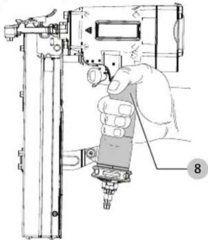
Proper Hand Position (Fig. B)
WARNING: To reduce the risk of serious personal injury, DAYS use proper hand position as shown.
WARNING: To reduce the risk of serious personal injury, ALWAYS hold securely in anticipation of a sudden reaction.
Proper hand position requires one hand on the handle 8. Fig. B
natural_image
Technical illustration of a hand operating a mechanical device with a numbered label (8), no readable text or symbols present.
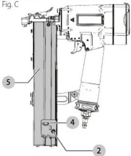
Loading Fasteners (Fig. C)
WARNING: Keep the tool pointed away from yourself and others. Serious personal injury may result.
WARNING: Never load fasteners with the contact trip or trigger activated. Personal injury may result.
WARNING: Always disconnect the tool from the air supply before making any adjustments or attempting any repairs to the tool.
- Move pusher 4 to rear until latched. Cover will open. Pusher will be held in place by the pusher release 2.
- Drop fasteners over magazine 5 and slide forward. Repeat until magazine is loaded.
- Pull pusher back slightly and depress pin detents. Allow pusher to slide forward over the pin detent.
ENGLISH
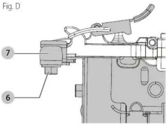
Adjusting Depth (Fig. D)
WARNING: To reduce risk of serious injury from an enteral actuation when attempting to adjust depth, ALWAYS:
- Disconnect the tool from the air supply.
- Avoid contact with trigger during adjustments.
The fastener depth control adjustment feature provides control of the fastener drive depth from flush with or just above the work surface to shallow or deep countersink.
-
Loosen depth adjustment screw 6 with 4 mm hex key.
-
Move sliding shoe 7 down (away from magazine) to decrease the drive depth or up (toward the magazine) to increase the drive depth.
-
Tighten screw with 4 mm hex key.
WARNING: To reduce the risk of injury, Always wear your eye [ANSI Z87.1 (CAN/CSA Z94.3)] and hearing protection [ANSI S12.6 (S3.19)] when operating this tool.
The tool can be actuated using one of two modes: sequential trip mode and contact trip mode.
Sequential Trip Operation (Fig. A)
The sequential trip mode gets its name from the "sequence" required to drive a fastener. To drive a fastener, the operator must first depress the "trip" FULLY against the work surface and then pull the trigger. To drive a second fastener, the operator must lift the tool from the work surface, release the trigger and then repeat the above sequence.
- The Sequential Trip mode offers a positive safety advantage since it will not accidentally drive a fastener if the tool is bumped against any surface or anybody while the operator is holding the tools with the trigger pulled.
- The Sequential Trip mode allows "place nailing" without the possibility of driving a second, unwanted fastener on recoil as described below under Contact Trip Operation.
To drive a fastener, the "trip" and the trigger must both be depressed. In conventional contact trip tools, the trigger may be depressed and held, and each "contact" between the trip and the work surface will drive a fastener.
- Single Fastener Placement (Place Fastening): First position the "trip" FULLY on the work surface, WITHOUT PULLING THE TRIGGER. Depress the "trip" FULLY until the nose of the tool touches the work surface and then pull the trigger to drive a fastener. Do not press the tool against the work surface with extra force. Instead, allow the tool to recoil off the work surface to avoid a second unwanted fastener.
NOTE: Remove your finger from the trigger after each operation.
- Rapid Fire Operation ("Bump" Fastening): First, hold the tool with the "trip" pointing towards but not touching the work surface. Pull the trigger and then tap or "bump" the trip against the work surface using a bouncing motion. Each depression of the "trip" will cause a fastener to be driven.
WARNING: Do not keep trigger pulled when tool is not to use.
Clearing a Jam (Fig. E, F)
WARNING: Always disconnect air supply before cleaning a jammed fastener.
On occasion fasteners can jam in the nose of a pneumatic stapler. This can be caused by striking a metal plate in the wall, drywall screw, or some other hard object. The DW451S2 stapler features open drive channel architecture for jam clearing. To clear a jam follow this procedure:
- Disconnect the tool from the air supply.
- Release the pusher so it is no longer applying force to the staples.
- Open the jam clearing nose door 11 by pulling up on the tool free jam release 9.
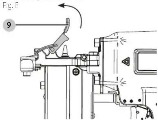
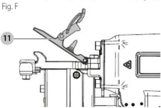
- Remove the jammed fastener. In certain circumstances, pliers may be required to remove the fastener.
- Close the tool free jam release.
- Release nail pusher back behind staples.
English
Cold Weather Operation
WARNING: To reduce the risk of serious personal injury, turn unit off and remove air supply before making any adjustments or removing/installing attachments or accessories. An accidental actuation can cause injury.
WARNING: Do not store tools in a cold weather environment to prevent frost or ice formation on the tools operating valves and mechanisms that could cause tool failure.
WARNING: Some commercial air line drying liquids are harmful to "O"-rings and seals—do not use these low temperature air dryers without checking compatibility.
When operating tools at temperatures below freezing:
- Make sure compressor tanks have been properly drained prior to use.
- Keep tool as warm as possible prior to use.
- Make certain all fasteners have been removed from magazine.
- Lower air pressure to 80 p.s.i.g. (5.7 kg/cm ^2 ) or less.
- Reconnect air and and load nails into magazine.
- Turn pressure up to operating level (not to exceed 120 p.s.i.g. [8.5 kg/cm ^2 ]) and use tool as normal.
- Always drain the compressor tanks at least once a day.
Hot Weather Operation
Tool should operate normally. However, keep tool out of direct sunlight as excessive heat can deteriorate bumpers, o-rings and other rubber parts resulting in increased maintenance.
MAINTENANCE
WARNING: To reduce the risk of serious personal injury, turn unit off and remove air supply before making any adjustments or removing/installing attachments or accessories. An accidental actuation can cause injury.
WARNING: Remove all fasteners from tool before performing tool operation check.
- With finger off the trigger, press the contact trip 3 against the work surface. ThE TOOI MUsT nOT CYCLE.
- Hold the tool off the work surface, and pull the trigger.
The Tool MUsT nOT CYCLE.
- With the tool off the work surface, pull the trigger. Press the contact trip against the work surface. ThE TOOI MUsT CYCIE.
- Without touching the trigger, press the contact trip against the work surface, then pull the trigger. ThE TOOI MUsT CYCLE.
Sequential Trip Operation
-
Press the contact trip against the work surface, without touching the trigger. The Tool MUsT not CYCLE.
-
Hold the tool off the work surface and pull the trigger. ThE TOOL MUsT nOT CYCIE. Release the trigger. The trigger must return to the trigger stop on the frame.
- Pull the trigger and press the contact trip against the work surface. The TOOI MUsT nOT CYCLE.
- With finger off the trigger, press the contact trip against the work surface. Pull the trigger. ThE TOOI MUSt CYCIE.
Accessories
WARNING: Since accessories, other than those offered by DEWALT, have not been tested with this product, use of such accessories with this tool could be hazardous. To reduce the risk of injury, only DEWALT recommended accessories should be used with this product.
Recommended accessories for use with your tool are available at extra cost from your local dealer or authorized service center. If you need assistance in locating any accessory, please contact DEWALT Industrial Tool Co., 701 East Joppa Road, Towson, MD 21286, call 1-800-4-DEWALT (1-800-433-9258) or visit our website: www.dewalt.com.
Repairs
WARNING: To assure product SAFETY and RESPONSIBILITY, repairs, maintenance and adjustment (including brush inspection and replacement, when applicable) should be performed by a DEWALT factory service center or a DEWALT authorized service center. Always use identical replacement parts.
Register Online
Thank you for your purchase. Register your product now for:
- WARRAnTY sERViCE: Registering your product will help you obtain more efficient warranty service in case there is a problem with your product.
- COnFiRMATiOn OF OWnERshiP: In case of an insurance loss, such as fire, flood or theft, your registration of ownership will serve as your proof of purchase.
- FOR YOUR SAFETY: Registering your product will allow us to contact you in the unlikely event a safety notification is required under the Federal Consumer Safety Act.
Register online at www.dewalt.com/register.
Seven Year Limited Warranty
DEWALT will repair, without charge, any defects due to faulty materials or workmanship for seven years from the date of purchase. This warranty does not cover part failure due to normal wear or tool abuse. For further detail of warranty coverage and warranty repair information, visit www.dewalt.com or call 1-800-4-DEWALT (1-800-433-9258). This warranty does not apply to accessories or damage caused where repairs have been made or attempted by others. THIS LIMITED WARRANTY IS GIVEN IN LIEU OF ALL OTHERS, INCLUDING THE IMPLIED WARRANTY OF MERCHANTABILITY AND FITNESS FOR A
English
PARTICULAR PURPOSE, AND EXCLUDES ALL INCIDENTAL OR CONSEQUENTIAL DAMAGES. Some states do not allow limitations on how long an implied warranty lasts or the exclusion or limitation of incidental or consequential damages, so these limitations may not apply to you. This warranty gives you specific legal rights and you may have other rights which vary in certain states or provinces. In addition to the warranty, DEWALT tools are covered by our:
1 YEAR FREE sERViCE
DEWALT will maintain the tool and replace worn parts caused by normal use, for free, any time during the first year after purchase.
90 DAY MOnEY BACK gUARAnTEE
If you are not completely satisfied with the performance of your DEWALT Power Tool, Laser, or Nailer for any reason, you can return it within 90 days from the date of purchase with a receipt for a full refund – no questions asked.
IATin AMERiCA: This warranty does not apply to products sold in Latin America. For products sold in Latin America, see country specific warranty information contained in the packaging, call the local company or see website for warranty information.
FREE WARning IABEL REPLACEMENT: If your warning labels become illegible or are missing, call 1-800-4-DEWALT (1-800-433-9258) for a free replacement.
Troubleshooting
| Problem Cause Correction |
| Trigger valve housing leaks air. O-ring cut or cracked. Replace O-ring. | |
| Trigger valve stem leaks air. O-ring/seals cut or cracked. Replace trigger valve assembly. | |
| Frame/nose leaks air. Loose nose screws. Tighten and recheck. | |
| O-ring or Gasket is cut or cracked. Replace O-ring or gasket. |
| Bumper cracked/worn. Replace bumper. |
| Frame/cap leaks air. Damaged gasket or seal. Replace gasket or seal. | |
| Cracked/worn head valve bumper. Replace bumper. |
| Loose cap screws. Tighten and recheck. |
| Failure to cycle. Air supply restriction. Check air supply equipment. | |
| Worn head valve O-rings. Replace O-rings. |
| Broken cylinder cap spring. Replace cylinder cap spring. |
| Head valve stuck in cap. Disassemble/Check. |
| Lack of power; slow to cycle. | Broken cylinder cap spring. Replace cap spring. |
| O-rings/seals cut or cracked. Replace O-rings/seals. |
| Exhaust blocked . Check bumper, head valve spring, muffler. |
| Trigger assembly worn/leaks. Replace trigger assembly. |
| Dirt/tar build up on driver. Disassemble nose/driver to clean. |
| Cylinder sleeve not seated correctlyon bottom bumper. Disassemble to correct. |
| Air pressure too low. Check air supply equipment. |
| Skipping fasteners; intermittent feed. | Worn bumper. Replace bumper. |
| Tar/dirt in driver channel. Disassemble and clean nose and driver. |
| Air restriction/inadequate air flow through quick disconnect socket and plug. Replace quick disconnect fittings. |
| Worn piston O-ring. Replace O-ring, check driver. |
| Damaged pusher spring. Replace spring. |
| Low air pressure. Check air supply system to tool. |
| Loose magazine nose screws. Tighten all screws. |
| Fasteners too short for tool. Use only recommended fasteners. |
| Bent fasteners. Discontinue using these fasteners. |
| Wrong size fasteners. Use only recommended fasteners. |
| Leaking head cap gasket. Tighten screws/replace gasket. |
| Trigger valve O-ring cut/worn. Replace O-ring. |
| Broken/chipped driver. Replace driver (check piston O-ring). |
| Worn magazine. Replace magazine. |
| Fasteners jam in tool. | Driver channel worn. Replace nose/check door. |
| Wrong size fasteners. Use only recommended fasteners. |
| Bent fasteners. Discontinue using these fasteners. |
| Loose magazine/nose screws. Tighten all screws. |
| Broken/chipped driver. Replace driver. |
natural_image
Illustration of a hand operating a mechanical device with a numbered label (8) pointing to the component.
Eje Central Lázaro Cárdenas No. 18 - Local (55) 5588 9377
D, Col. Obrera
MERIDA, YUC
Calle 63 #459-A - Col. Centro (999) 928 5038
MONTERREY, N.L.
Av. Francisco I. Madero 831 Poniente - Col. (818) 375 23 13 Centro
PUEBLA, PUE
17 Norte #205 - Col. Centro (222) 246 3714
QUERETARO, QRO
Av. San Roque 274 - Col. San Gregorio (442) 2 17 63 14
SAN LUIS POTOSI, SLP
natural_image
Pure geometric lines forming a symmetrical shape with no text, numbers, or symbols

natural_image
Pure geometric lines without any text, numbers, or symbols

natural_image
Pure geometric lines forming a symmetrical shape with no text, numbers, or symbols

natural_image
Pure geometric lines without any text, numbers, or symbols

natural_image
Pure geometric lines forming a symmetrical shape with no text, numbers, or symbols
DEWALT Industrial Tool Co., 701 East Joppa Road, Towson, MD 21286
(AUG18) Part No. N565321 DW451S2 Copyright © 2018 DEWALT
The following are trademarks for one or more DEWALT power tools: the yellow and black color scheme, the "D" shaped air intake grill, the array of pyramids on the handgrip, the kit box configuration, and the array of lozenge-shaped humps on the surface of the tool.


