P85049 - Powerline Adapter MEDION - Free user manual and instructions
Find the device manual for free P85049 MEDION in PDF.
| Product type | Powerline adapter (HomePlug AV) |
| Model | P85049 (MD 87309) |
| Brand | Medion |
| Dimensions (approx.) | 7 x 5 x 4 cm |
| Unit weight | Approx. 183 g |
| Power supply | 100-240 V~, 50/60 Hz, 0.1 A |
| Power consumption | < 3 W (operation), < 0.5 W (standby) |
| Connectivity | 1 RJ-45 Ethernet port 100 Mbit/s, integrated power socket (max 16 A) |
| Transmission speed | Up to 500 Mbit/s |
| Standard and encryption | IEEE P1901, HomePlug AV, AES 128-bit encryption |
| Main functions | Network extension via powerline, automatic pairing, standby mode, SECURITY/RESET button |
| Security | AES encryption, electrostatic discharge protection |
| Maintenance and cleaning | Clean with a soft, lint-free cloth; unplug before cleaning |
| Recycling | Do not dispose of with household waste; follow local regulations (WEEE) |
| Package contents | 1 adapter, 1 RJ-45 cable, instruction manual, warranty card |
| Warranty | 2 years (Medion standard) |
Frequently Asked Questions - P85049 MEDION
User questions about P85049 MEDION
0 question about this device. Answer the ones you know or ask your own.
Ask a new question about this device
Download the instructions for your Powerline Adapter in PDF format for free! Find your manual P85049 - MEDION and take your electronic device back in hand. On this page are published all the documents necessary for the use of your device. P85049 by MEDION.
USER MANUAL P85049 MEDION
natural_image
Two 3D-rendered camera modules with circular lens symbols, one pointing at a square (no text or labels)natural_image
Symbol of a trash bin with crossed lines indicating no waste or discharge (no text or labels)text_image
QR code image containing encoded data, no visible human-readable textTable of contents
DE
1. Notes on how to use these instructions .... 31
1.1. Symbols and keywords used in these instructions ....31
EN
FR
- Package contents ......
- Proper use
- Safety instructions ....
4.1. Operational safety 34
4.2. Electromagnetic compatibility .....36
4.3. Notes on conformity ......36
4.4. Transport and packaging ....37
- System requirements
- Functionality 38
- Overview of the device 39
- Possible LED displays 40
- The SECURITY/RESET button .... 41
- Connections 42
10.1. Notes on the electricity connection....42
10.2. Connection with a network device .....44
-
Removing a Powerline Adapter ...... 47
-
Energy-saving mode...... 47
- Factory settings 48
- Troubleshooting 48
- Cleaning.... 52
- Disposal 52
- Technical data 53
18. Legal notice ....
1. Notes on how to use these instructions

Read the safety instructions carefully before use. Note the warnings on the device and in the operating instructions.
Always keep the operating instructions close to hand. If you sell the device or give it away, make sure you also hand over these instructions and the warranty card.
1.1. Symbols and keywords used in these instructions

DANGER!
Warning: immediate mortal danger!
WARNING!
Warning of possible risk of fatal injury and/or serious irreversible injuries!

CAUTION!
Please follow the instructions to prevent injuries and property damage!
ATTENTION!
Please follow the guidelines to avoid property damage!

NOTE!
Additional information on using the device.

NOTE!
Please follow the guidelines in the operating instructions!
WARNING!
Warning of risk of electric shock!
Bullet point/information on operating steps and results
Tasks to be performed
2. Package contents
Please check your purchase to ensure that all items are included. If anything is missing, please contact us within 14 days of purchase. The following items are supplied with your Powerline Adapter Set:
-1 x Powerline Adapter
-1 x Network Cable RJ-45
-Instruction Manual and Warranty Certificate
3. Proper use
The Powerline Adapters are designed to transfer network signals via the sockets connected to the mains electricity network. This device is for private use only and may not be used for commercial purposes.
4. Safety instructions
4.1. Operational safety
- This device is not intended for use by people (including children) with reduced physical, sensory or mental abilities or by those without experience and/or knowledge, unless they are supervised by a person responsible for their safety or they have been instructed in its use by that person. Children should be supervised to ensure they do not play with this device.
• Always adhere to the user instructions of those devices that you connect to the Powerline Adapters. - Do not place liquid containers, e.g. vases, on or near the device. The container may tip over and the liquid may impair the electrical safety of the device.
-
Keep the device away from moisture and from water in droplet or spray form. Avoid vibrations, dust, heat and direct sunlight in order to prevent malfunction. The operating temperature is 5° - 35° C.
-
Never open the housing on the devices; they do not contain any parts requiring maintenance! There is a risk of electric shock when the housing is open. This would invalidate the warranty and may render the device unusable.
- Plug the Powerline Adapter into freely accessible sockets for your mains electricity network so that it can be quickly disconnected from the mains electricity network in the event of danger.
- After transporting the device, wait until it has reached room temperature before switching it on. Major fluctuations in temperature or humidity can lead to condensation which could cause an electrical short-circuit.
- To avoid static charges, you should not operate the device in extremely dry conditions.
- In circumstances where there are electrostatic discharges, the device could malfunction. In this case, the device must be reset to the factory settings.
4.2. Electromagnetic compatibility
- You must comply with the European directives on electromagnetic compatibility (EMC) when making connections. Keep the device at a distance of at least one metre from sources of high-frequency or magnetic interference (televisions, loudspeakers, mobile telephones, etc.) to avoid malfunctions and data loss.
4.3. Notes on conformity
CE MEDION AG hereby declares that the MD 87309 Powerline Adapter conforms to the following European requirements:
• EMC Directive 2004/108/EC
- Low Voltage Directive 2006/95/EC
• Ecodesign Directive 2009/125/EC
• RoHS Directive 2011/65/EU.
Full declarations of conformity are available at www.medion.com/conformity.
4.4. Transport and pack aging
Keep the original packaging in the event the device needs to be sent in the post.
5. System requirements
Ensure that your computer meets the following requirements before installing the Powerline Adapter:
-1 wall socket (100-240 V\~50/60 Hz).
-LAN connection
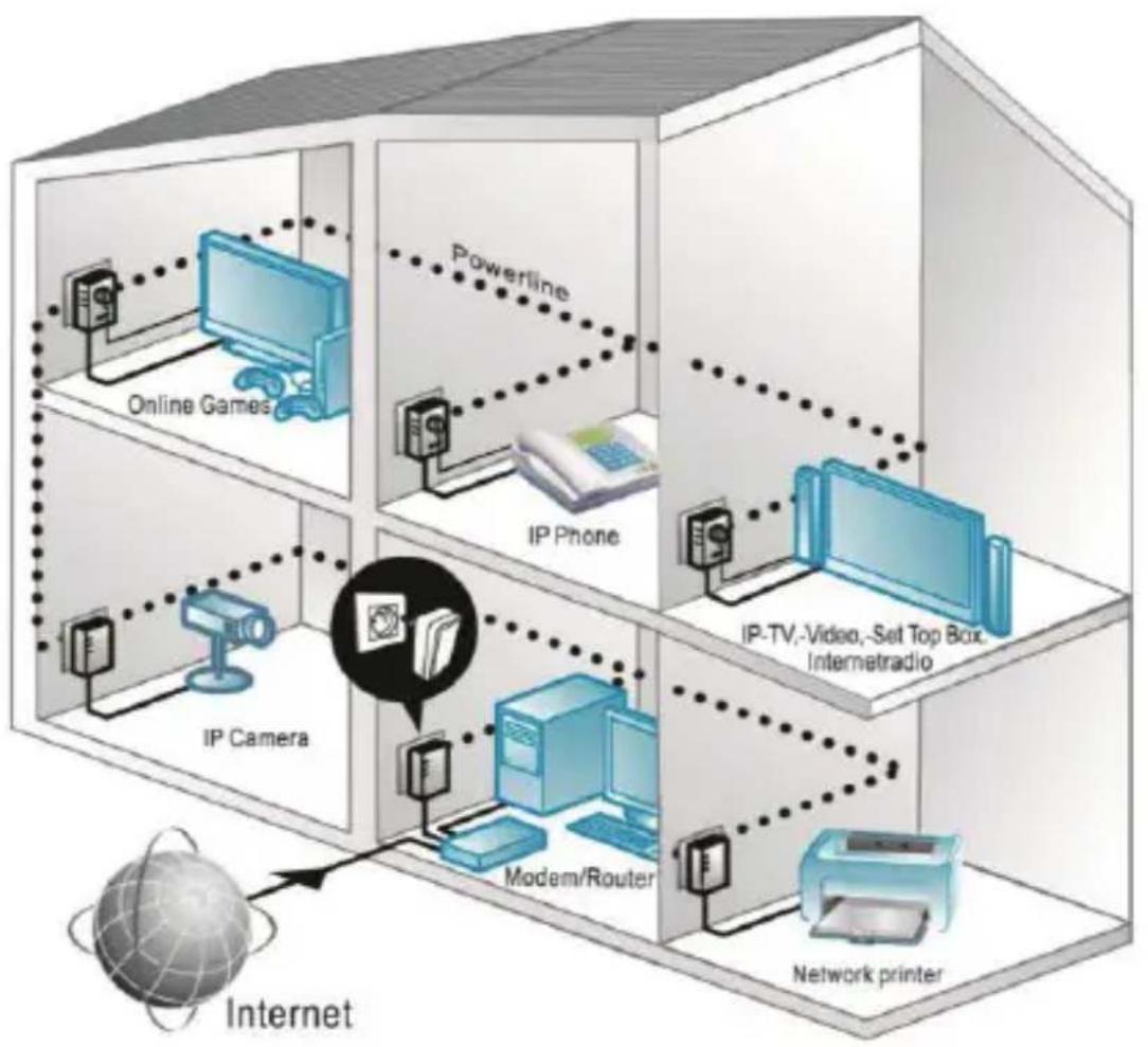
6. Functionality
The Powerline Adapters can be used to extend your existing LAN network using the mains electricity network available in your household, without having to lay additional cables.
flowchart
graph TD
    A["Internet"] --> B["Modem/Router"]
    B --> C["IP Camera"]
    C --> D["IP Phone"]
    D --> E["Powerline"]
    E --> F["Online Games"]
    F --> G["Network printer"]
    G --> H["IP-TV,-Video,-Set Top Box, Intemetradio"]
Example of Use
7. Overview of the device
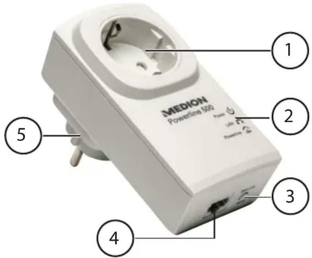
text_image
MEDION Powerline 500 1 2 3 4 51) Integrated socket
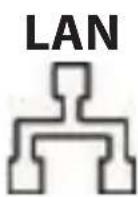
2) LED displays: POWER, LAN and POWERLINE
3) SECURITY/RESET button: encryption/resets the device to the factory settings
4) RJ-45 LAN connection
5) Mains power plug
8. Possible LED displays
| LED Status Meaning | ||
Power | Green light | The adapter is switched on. |
| Flashes green | -The adapter is restarting or carrying out security settings | |
| Flash-es green every 15 seconds (other LED displays are off) | The adapter is ready for operation (standby). | |
| Off | The adapter is not being supplied with electricity. | |
 | Green light | LAN cable is connected, adapter is ready to transfer data. |
| Flashes green | Data is being transferred. | |
| Off | The LAN connection is not active (no LAN cable connected, network device is switched off). | |
Power-line | Green light | Another Powerline Adapter has been detected in the same network. |
| Off | No connection to another adapter or no device with the same network key has been detected. | |
| Green Signal > 40 Mbit/s | ||
| Orange Signal 20 - 40 Mbit/s | ||
| Red Signal ≤ 20 Mbit/s | ||
9. The SECURITY/RESET button
The SECURITY/RESET button has three functions depending on how long it is pressed:
| Seconds Function | |
| 1-2 Connects to an existing Powerline network | |
| 5-8 Generates a random, unique network key on the adapter and immediately separates the device from an existing network. | |
| 10-15 Resets the adapter to the factory settings. |
10. Connections
In order to create a network with the Powerline Adapters, it is necessary for at least two adapters to be connected for the purpose of transferring data.
There are two options available: A direct connection between two network-capable devices or a connection between a network-capable device and a router (to the Internet).
Connect the Powerline Adapter to a wall socket (100-240 V\~50/60 Hz) near to the network-capable device.

NOTE
In order to ensure constant access to an existing LAN network, it is necessary to permanently supply the Powerline Adapter with electricity.
10.1. Notes on the electricity connection

NOTE
Directly connect the Powerline Adapter to a wall socket and not to an extension cable or multiple socket adapter because otherwise this may negatively influence the quality of the data transmission. You can operate other devices via the integrated power socket on the Powerline Adapter.
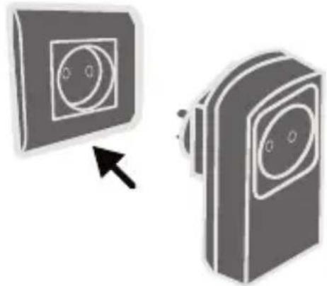
natural_image
Two gray 3D-rendered camera modules with circular lens symbols, one pointing at a black arrow (no text or labels)If possible, directly plug the Powerline Adapter into its own wall socket.

NOTE
If you cannot achieve a connection after linking the adapter to a computer, try the process again using a different wall socket. Please note that the quality of the data transmission is dependent on the load and quality of your mains electricity network:
–The data transmission will slow down as the length of the power line between the two Powerline Adapters increases.
- Depending on the load placed on the mains electricity network, the speed of the data transmission may vary or even be interrupted.
-In the case of older mains electricity networks, which do not correspond to the latest technological standards, the data transmission may be a little slower.
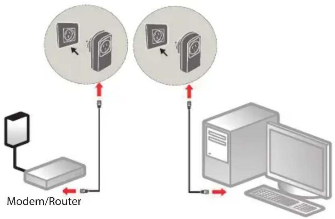
10.2. Connection with a network device
In order to connect two network devices e.g. a PC and a router together in a network using Powerline Adapters, each of the two devices must be connected to their own Powerline Adapter with a LAN cable (RJ-45).
flowchart
graph TD
    A["Modem/Router"] -->|Red Arrow| B["Device 1"]
    B --> C["Device 2"]
    C --> D["Computer"]
    D -->|Red Arrow| E["Device 3"]
    E --> F["Device 4"]
    style A fill:#f9f,stroke:#333
    style B fill:#ccf,stroke:#333
    style C fill:#cfc,stroke:#333
    style D fill:#fcc,stroke:#333
    style E fill:#cff,stroke:#333
    style F fill:#ffc,stroke:#333
Connection example
Connect the supplied LAN cable (RJ-45) with the LAN connection on the Powerline Adapter and the LAN connection on the router.
Connect the LAN connection on the computer with the LAN connection on the second Powerline Adapter using the second LAN cable (RJ-45) supplied in the set.
▶ If possible, directly plug each Powerline Adapter into its own wall socket.
▶ Switch on the computer and the router.
The setup process has been successful if all three LED displays POWER, LAN and POWERLINE light up on both Powerline Adapters. Integrating the adapter into the network

NOTE
For this process, it is helpful to plug all of the adapters, which are to receive the new network key, next to each other in a multiple socket adapter.
Proceed as follows for each additional Powerline Adapter that is to receive the new network key:
All of the Powerline Adapters to be configured are connected and ready for operation. The POWER LED lights up.
Connect the adapter that is to be used to extend the network to a wall socket. The POWER LED lights up.
▶ Press the SECURITY/RESET button on this Powerline Adapter for approx. 5 - 8 seconds.
The device will be reset and then restarts. All LED displays will briefly go out. This Powerline Adapter has now generated a random, unique network key.
▶ Press the SECURITY/RESET button on the adapter
in the existing network for approx. 1 - 2 seconds.
The Power LED flashes in green.
Now press the SECURITY/RESET button on the adapter that you want to add to the existing network within two minutes.
The Power LED flashes in green.
When the POWER LED and also the POWERLINE LED are permanently lit in green on all Powerline Adapters, the addition of the new adapter and the encryption process have been successfully completed.

NOTE
Complete the process described above for each additional Powerline Adapter.
11. Removing a Powerline Adapter
If you want to remove a Powerline Adapter from the existing network, proceed as follows:
▶ Press the SECURITY/RESET button on the Powerline Adapter you want to remove from the network for approx. 5 - 8 seconds.
All LED displays will briefly go out. The device will be reset and then restarts. All LED displays will briefly go out. This Powerline Adapter has now generated a random, unique network key and is thus no longer connected to the network. The POWERLINE LED no longer lights up.
12. Energy-saving mode
If the network devices are switched off and no data is being transmitted, the Powerline Adapters will switch to standby mode after approx. one minute. The Power display will flash in standby mode.
Once the network devices are switched on again, the Powerline Adapters will also be restarted.
13. Factory settings
Both of the Powerline Adapters included in the set you have purchased are paired on delivery.
This default setting will be lost if the network key is changed or individual adapters are separated from the network.
How to reset the factory settings:
▶ Press the SECURITY/RESET button on both Powerline Adapters for approx. 10 - 15 seconds.
All LED displays will briefly go out. The device will be reset and then restarts. The process has been completed when the Power LED is constantly lit.
14. Troubleshooting
If errors occur, check first whether you can correct the problem yourself. The following list may help you.

CAUTION Never try to repair the device yourself. Contact our service centre or another suitable specialist workshop if a repair is necessary.
| Problem Possible cause Remedy | ||
| The POWER LED does not light up | Is the Powerline Adapter correctly connected to the mains electricity network? | ▸ If necessary, unplug the Power-line Adapter and plug it in again. |
| The LAN LED does not light up | Is the LAN cable (RJ-45) correctly connected to the adapter and the computer or router? | ▸ If necessary, check the LAN card and/or the DSL connection on your computer. |
| Is the computer/ router switched on? | ▸ Switch on the network device. | |
| The POWER-LINE LED does not light up | There is no connection between the Powerline Adapters. | |
| • It is possible that the mains sockets you are using are not suitable for generating a Powerline connection.The adapters may not be synchronised. | ▶ Try again using different mains sockets.You can test whether the adapters are located in the same network:Plug in both of the adapters next to each other in a multiple socket adapter.If the Powerline LED does not now light up, the adapters are not located in the same network.In this case, carry out the reset process on all adapters. | |
15. Cleaning
• Always unplug the Powerline Adapter and disconnect all the cables before cleaning the device.
- Do not use solvents, corrosive agents or aerosol-based detergents to clean the device.
- Clean the device using a soft, lint-free cloth.
Please keep the packaging and do not use anything other than this packaging to transport the device.

CAUTION!
None of the parts inside the device require cleaning or maintenance.
16. Disposal
Packaging

Your device is packaged to protect it from damage in transit. Packaging materials are raw materials and can therefore be reused or recycled.
Device

natural_image
Symbol of a trash bin crossed with no text or numbers, representing waste sorting or disposal (no text present)Do not under any circumstances dispose of the device with the household rubbish at the end of its service life! Please consult your local authority for advice on correct and eco-friendly methods of disposal.
17. Technical data
Model: MD 87309 (device)
Input voltage: 100 – 240 V\~50/60 Hz, 0.1 A
Output voltage
(integrated socket): 100 - 240 V\~/
Maximum load 16 A
Power consumption: < 3 W operation
< 0.5 W standby mode
Connections: Ethernet (LAN) 100Mbit/s
Transfer speed: up to 500 Mbit/s.
Powerline AV standard: 128-bit AES encryption
Protocol HomePlug AV, compatible
with IEEE P1901, compatible
with 200 and 500 Mbit/s
Powerline Adapters,
coexistent with HomePlug 1.0
Environmental requirements
Temperature (operation) 5°C - 35°C
Temperature (storage) -20°C - 70°C
Humidity (operation) 10% - 90%, non-condensing
Humidity (storage) 5% - 95%, non-condensing
Dimensions (W x H x D) 61 x 116 x 86 mm
Weight (per adapter) approx. 183 g
18. Legal notice
Copyright © 2015
All rights reserved.
This operating manual is protected by copyright.
Mechanical, electronic and any other form of reproduction is prohibited without the written permission of the manufacturer
Copyright is owned by the company:
Medion AG
Am Zehnthof 77
45307 Essen
Germany
The operating manual can be reordered via the service hotline and is available for download via the service portal at www.medion.com/au/service/start/.
You can also scan the QR code above and download the operating manual onto your mobile device via the service portal.

text_image
QR code image containing encoded data, no visible human-readable textSommaire
DE
natural_image
Two 3D-rendered camera modules with circular lens symbols, one pointing to a screen (no text or labels)natural_image
Symbol of a trash bin with crossed lines indicating no waste or discharge (no text or labels)Protocole HomePlug AV, compatible
(stockage): 5–95 %, sans condensation
Dimensions
(I x H x P): 61 x 116 x 86 mm