KRPR36YW - Fridge Hestan - Free user manual and instructions
Find the device manual for free KRPR36YW Hestan in PDF.
User questions about KRPR36YW Hestan
0 question about this device. Answer the ones you know or ask your own.
Ask a new question about this device
Download the instructions for your Fridge in PDF format for free! Find your manual KRPR36YW - Hestan and take your electronic device back in hand. On this page are published all the documents necessary for the use of your device. KRPR36YW by Hestan.
USER MANUAL KRPR36YW Hestan
Refrigerators, Freezers and Wine Storage
KRP/KRB/KRC/KFC/KWC/KRW
Installation Manual
WARNING
IF THE INFORMATION IN THIS MANUAL IS NOT FOLLOWED EXACTLY, A FIRE OR EXPLOSION MAY RESULT CAUSING PROPERTY DAMAGE, PERSONAL INJURY, OR DEATH.
Do not store or use gasoline or other flammable vapors and liquids in the vicinity of this or any other appliance.
Installation and service must be performed by a qualified installer or service agency.
DO NOT REPAIR, REPLACE OR REMOVE ANY PART OF THE APPLIANCE UNLESS SPECIFICALLY RECOMMENDED IN THE MANUAL. IMPROPER INSTALLATION, SERVICE OR MAINTENANCE CAN CAUSE INJURY OR PROPERTY DAMAGE. REFER TO THIS MANUAL FOR GUIDANCE. ALL OTHER SERVICING SHOULD BE DONE BY A QUALIFIED TECHNICIAN.
READ THESE INSTRUCTIONS CAREFULLY AND COMPLETELY BEFORE INSTALLING OR USING YOUR APPLIANCE TO REDUCE THE RISK OF FIRE, BURN HAZARD, OR OTHER INJURY. KEEP THIS MANUAL FOR FUTURE REFERENCE.
SAFETY DEFINITIONS
WARNING
THIS INDICATES THAT DEATH OR SERIOUS INJURY MAY OCCUR AS A RESULT OF NOT OBSERVING THIS WARNING
CAUTION
THIS INDICATES THAT MINOR OR MODERATE INJURY MAY OCCUR AS A RESULT OF NOT OBSERVING THIS WARNING.
NOTICE
THIS INDICATES THAT DAMAGE TO THE APPLIANCE OR PROPERTY MAY OCCUR AS A RESULT OF NOT OBSERVING THIS WARNING.
INSTALLER: LEAVE THIS MANUAL WITH THE OWNER OF THE APPLIANCE. HOMEOWNER: RETAIN THIS MANUAL FOR FUTURE REFERENCE.
1 SAFETY PRECAUTIONS-BEFORE YOU BEGIN
2 MODEL NUMBERS
3 RATING LABEL
3 REGULATORY / CODE REQUIREMENTS
4 IMPORTANT CHILD SAFETY
4 LOCATION AND PREPARATION
12 CONNECTIONS
15 OVERLAY PANELS
27 FINAL INSTALLATION
36 TESTING AND INITIAL START UP
38 PARTS AND SERVICE
SAFETY PRECAUTIONS - BEFORE YOU BEGIN
When properly cared for, your Hestan appliance will provide safe, reliable service for many years. When using this appliance, basic safety practices must be followed as outlined below.
IMPORTANT: Save these instructions for the local Utility Inspector's use.
INSTALLER: Please leave these Installation Instructions with the owner.
OWNER: Please retain these Installation Instructions for future reference.
This appliance is NOT designed for installation in manufactured (mobile) homes or recreational park trailers. Do NOT install this appliance outdoors.
WARNING
ELECTRICAL SHOCK HAZARDELECTRICAL SHOCK HAZARD
Disconnect power before installing or servicing appliance. Failure to do so can result in death or electrical shock.

ELECTRICAL GROUNDING ELECTRICAL GROUNDING
- This appliance must be grounded. Grounding reduces the risk of electric shock in the event of a short circuit. Read the CONNECTIONs section of this manual for complete instructions.
DO NOT ground to a gas pipe.
DO NOT use an extension cord with this appliance. - DO NOT have a fuse in the NEUTRAL or GROUNDING circuit. A fuse in the NEUTRAL or GROUNDING circuit could result in an electrical shock.
| Model Description |
| KRPR36 Bottomom Mount Refrigerator, Top Compressor, Pro, Right Hinged, 36" |
| KRPL36 Bottomom Mount Refrigerator, Top Compressor, Pro, Left Hinged, 36" |
| KRPR36-XX Bottom Mount Refrigerator, Top Compressor, Pro, Color, Right Hinged, 36" |
| KRPL36-XX Bottom Mount Refrigerator, Top Compressor, Pro, Color, Left Hinged, 36" |
| KRBR36 Bottomom Mount Refrigerator, Bottom Compressor, Right Hinged, 36" |
| KRBL36 Bottomom Mount Refrigerator, Bottom Compressor, Left Hinged, 36" |
| KRBR36-OV Bottom Mount Refrigerator, Bottom Compressor, Overlay, Right Hinged, 36" |
| KRBL36-OV Bottom Mount Refrigerator, Bottom Compressor, Overlay, Left Hinged, 36" |
| KRBR36-XX Bottom Mount Refrigerator, Bottom Compressor, Color, Right Hinged, 36" |
| KRBL36-XX Bottom Mount Refrigerator, Bottom Compressor, Color, Left Hinged, 36" |
| KRCR24 Refrigerator Column, Right Hinged, 24" |
| KRCL24 Refrigerator Column, Left Hinged, 24" |
| KRCR24-OV Refrigerator Column, Overlay, Right Hinged, 24" |
| KRCL24-OV Refrigerator Column, Overlay, Left Hinged, 24" |
| KRCR24-XX Refrigerator Column, Color, Right Hinged, 24" |
| KRCL24-XX Refrigerator Column, Color, Left Hinged, 24" |
| KRCR30 Refrigerator Column, Right Hinged, 30" |
| KRCL30 Refrigerator Column, Left Hinged, 30" |
| KRCR30-OV Refrigerator Column, Overlay, Right Hinged, 30" |
| KRCL30-OV Refrigerator Column, Overlay, Left Hinged, 30" |
| KRCR30-XX Refrigerator Column, Color, Right Hinged, 30" |
| KRCL30-XX Refrigerator Column, Color, Left Hinged, 30" |
FREEZERMODELS FREEZERMODELS
| Model Description |
| KFCR18 Freezer Column, Right Hinged, 18" |
| KFCL18 Freezer Column, Left Hinged, 18" |
| KFCR18-OV Freezer Column, Overlay, Right Hinged, 18" |
| KFCL18-OV Freezer Column, Overlay, Left Hinged, 18" |
| KFCR18-XX Freezer Column, Color, Right Hinged, 18" |
| KFCL18-XX Freezer Column, Color, Left Hinged, 18" |
| KFCR24 Freezer Column, Right Hinged, 24" |
| KFCL24 Freezer Column, Left Hinged, 24" |
| KFCR24-OV Freezer Column, Overlay, Right Hinged, 24" |
| KFCL24-OV Freezer Column, Overlay, Left Hinged, 24" |
| KFCR24-XX Freezer Column, Color, Right Hinged, 24" |
| KFCL24-XX Freezer Column, Color, Left Hinged, 24" |
| KFCR30 Freezer Column, Right Hinged, 30" |
| KFCL30 Freezer Column, Left Hinged, 30" |
| KFCR30-OV Freezer Column, Overlay, Right Hinged, 30" |
| KFCL30-OV Freezer Column, Overlay, Left Hinged, 30" |
| KFCR30-XX Freezer Column, Color, Right Hinged, 30" |
| KFCL30-XX Freezer Column, Color, Left Hinged, 30" |
WINE MODELSWINE MODELS
| Model No. Description | |
| KWCR18 Wine Column, Right Hinged, 18" | |
| KWCL18 Wine Column, Left Hinged, 18" | |
| KWCR18-OV Wine Column, Overlay, Right Hinged, 18" | |
| KWCL18-OV Wine Column, Overlay, Left Hinged, 18" | |
| KWCR18-XX Wine Column, Color, Right Hinged, 18" | |
| KWCL18-XX Wine Column, Color, Left Hinged, 18" | |
| KWCR24 | Wine Column, Right Hinged, 24" |
| KWCL24 | Wine Column, Left Hinged, 24" |
| KWCR24-OV | Wine Column, Overlay, Right Hinged, 24" |
| KWCL24-OV | Wine Column, Overlay, Left Hinged, 24" |
| KWCR24-XX | Wine Column, Color, Right Hinged, 24" |
| KWCL24-XX | Wine Column, Color, Left Hinged, 24" |
| KRWR24 | Refrigerator with Wine, Right Hinged, 24" |
| KRWL24 Refrigerator with Wine, Left Hinged, 24" | |
| KRWR24-OV Refrigerator with Wine, Overlay, Right Hinged, 24" | |
| KRWL24-OV Refrigerator with Wine, Overlay, Left Hinged, 24" | |
| KRWR24-XX Refrigerator with Wine, Color, Right Hinged, 24" | |
| KRWL24-XX Refrigerator with Wine, Color, Left Hinged, 24" | |
NOTE: -XX indicates color model. NOTE: -XX indicates color model.
-BK for Stealth - Black -WH for Froth - White -RD for Matador - Red
-YW for Sol - Yellow
-OR for Citra - Orange
-BC for Tin Roof - Burgundy
-PP for Lush - Purple
-BU for Prince - Blue
-GR for Grove - Green
-GG for Pacific Fog - Graphite Gray
-TQ for Bora Bora - Turquoise
RATING LABEL
The rating label contains important information about your Hestan appliance such as the model, serial number, and electrical rating.
The rating label is located on the inside wall of the appliance.
If service is necessary, contact Hestan Customer Care with the model and serial number information shown on the label.
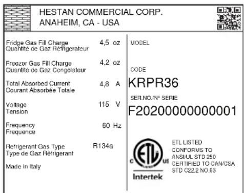
TYPICAL RATING LABEL
REGULATORY / CODE REQUIREMENTS
Installation of this appliance must be made in accordance with local codes. In the absence of local codes, this unit should be installed in accordance with the National Electrical Code and local codes.
This appliance must be electrically grounded in accordance with local codes or in the absence of local codes with the National Electrical Code ANSI/NFPA 70, or Canadian Electrical code CSA C22.1.
WARNING
Risk of child entrapment. Before you throw away your old refrigerator or freezer:
Take off the doors
- Leave the shelves in place so that children may not easily climb inside.
LOCATION AND PREPARATION
PREPARATION AND UNPACKING PREPARATION AND UNPACKING
Before moving the refrigerator:
- Protect any finished flooring to prevent damage.
- The grille and trim pieces are packaged on the back of the unit. Handles and other items may also be packaged on the back. Remove all such items before removing the appliance from the pallet. See "PREPARING THE INSTALLATION" on page 10 for additional information.
Make sure that power can be provided to the location selected.
PACKAGED DIMENSIONS AND WEIGHTSPACKAGED DIMENSIONS AND WEIGHTS
| Width Height Depth | Weight | |||
| 18" Models 28-11/32" [720 mm] 89" | [2260 mm] 30-1/8" | [765 mm] 342 lb | [155 kg] | |
| 24" Models 28-11/32" [720 mm] 89" | [2260 mm] 30-1/8" | [765 mm] 507 lb | [230 kg] | |
| 30" Models 34-1/4" [870 mm] 89" | [2260 mm] 30-1/8" | [765 mm] 606 lb | [275 kg] | |
| 36" Models 40-5/32" [1020 mm] 89" | [2260 mm] 30-1/8" | [765 mm] 650 lb | [295 kg] |
ELECTRICAL AND WATER SUPPLY ELECTRICAL AND WATER SUPPLY
Electrical requirement: 115V 60Hz 15A
Units with icemaker: Connect to potable water only.
Supply pressure: If using external filtration, from 7.3 to 73 psi [0.5 - 5.0 Bar]
If using supplied water filter, from 25.4 to 73 psi [1.75 - 5.0 Bar].
Water supply tube: 3 / 4'' female attachment (see the notice on page 13 for details)
PROVIDED INSTALLATION ACCESSORIES
Customized panel mounting kit (included with -OV models only)
Anti-tip kit
Lateral/side connecting kit
See "PREPARING THE INSTALLATION" on page 10 for unpacking information.
TOOLS
The following tools are needed for the installation of the appliance:
- Phillips screw driver
- Drill and 1/8'' drill bit, plus 3/8'' bit for masonry
17mm (or 11/16") open-end or adjustable wrench - 13mm (or 1/2'' ) socket, extension, and handle
- 2.5 mm and 4mm allen wrenches
If installing two units together
- Hand rivet tool (Pop rivet gun)
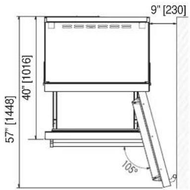
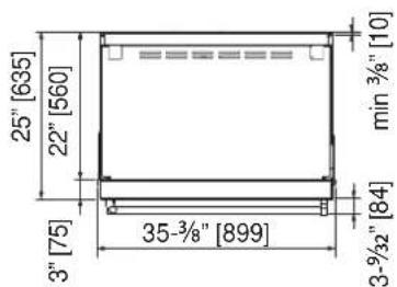
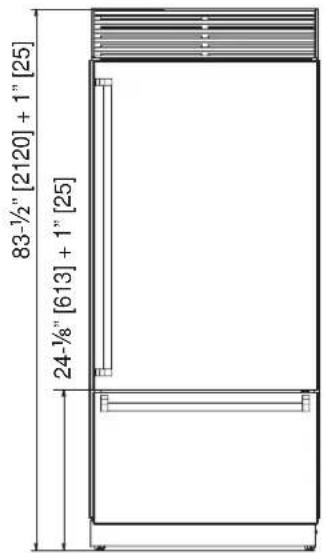
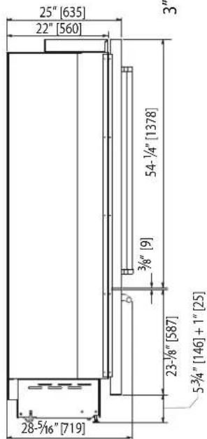
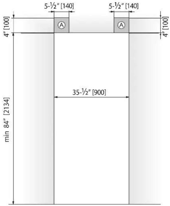
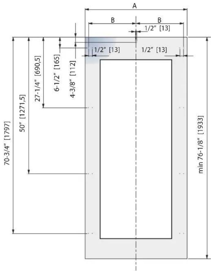
INSTALLATION CUT-OUT - KRP MODELSINSTALLATION CUT-OUT - KRP MODELS
| Cut-out Height 84" [2] | 134 mm] Cut-out Width 35-1/2" [900 mm] | ||
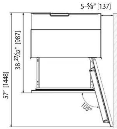
| Door Swing Clearance | 57" [1448 mm] | Door Opening Angle | 105° |
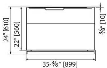
| Width 35-3/8" [899 m] | m] Height 83-1/2" [2120 mm] + 1" [25 mm] | ||
| Depth with door 25" | 635 mm] | ||
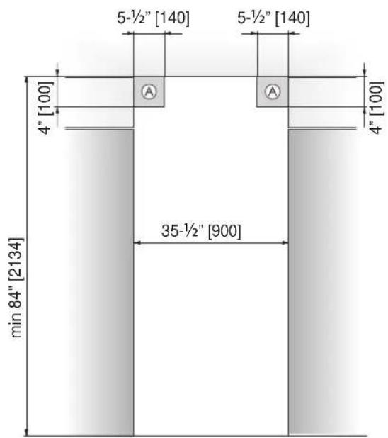
Area to be left clear for the anti-tip brackets

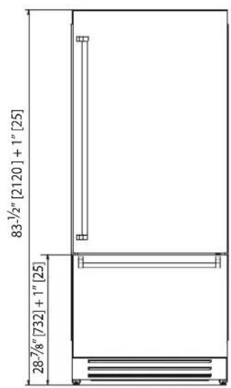
INSTALLATION CUT-OUT - KRB MODELS - SS OR COLOR
| Cut-out Height 84" | [2134 mm] Cut-out Width 35-1/2" [900 mm] | ||
| Door Swing Clearance | 57" [1448 mm] | Door Opening Angle | 105° |
| Width 35-3/8" [899 mm] Height 83-1/2" [2120 mm] + 1" [25 mm] | |||
| Depth with door 25" [635 mm] | |||

Area to be left clear for the anti-tip brackets

INSTALLATION CUT-OUT - KRB-OV MODELS WITH OVERLAY
| Cut-out Height 84" | [2134 mm] Cut-out Width | 35-1/2" [900 mm] | |
| Door Swing Clearance | 57" [1448 mm] | Door Opening Angle | 105° |
| Width 35-3/8" [899 mm] Height 83-1/2" [2120 mm] + 1" [25 mm] | |||
| Depth with door (without panel) | 24" [610 mm] | ||
Area to be left clear for the anti-tip brackets
Images show unit WITHOUT overlay panel attached.
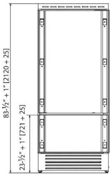
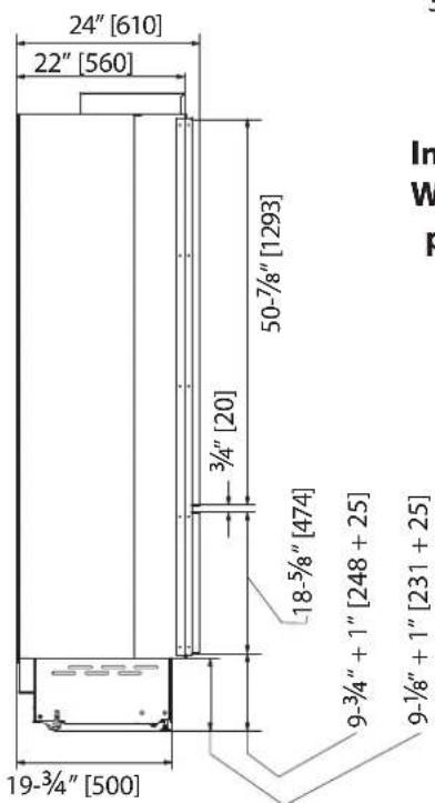
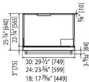
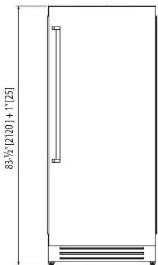
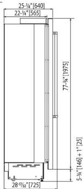
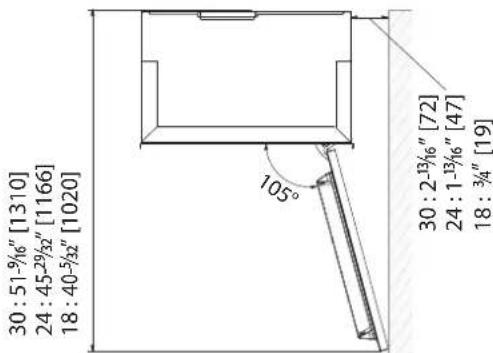
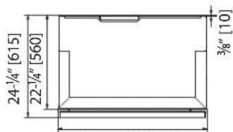
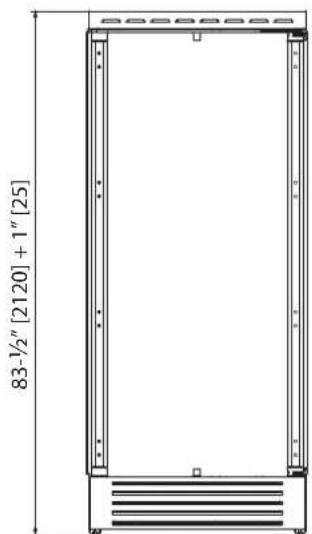
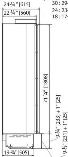
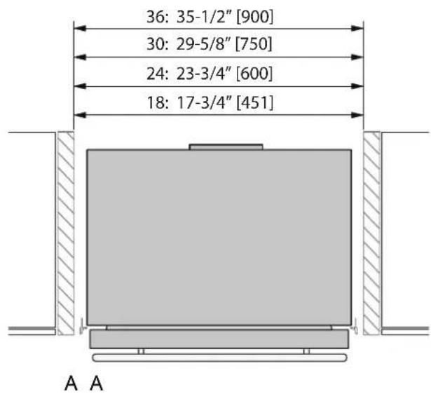
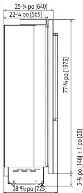
INSTALLATION CUT-OUT - KRC, KFC, KWC, KRW MODELS - SS OR COLOR
18", 24" AND 30" COLUMN REFRIGERATORS AND FREEZERS
18", 24" WINE COLUMN AND 24" REFRIGERATOR WITH WINE
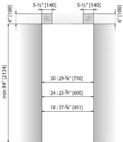
| Cut-out Height Cut-out Width | |||
| 18" models 84" [21] | 4 mm] 18" models 17-3/4" | [451 mm] | |
| 24" models 84" [21] | 4 mm] 24" models 23-3/4" | [600 mm] | |
| 30" models 84" [21] | 4 mm] 30" models 29-5/8" | [750 mm] | |
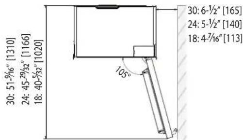
| Door Swing Clearance Width | |||
| 18" models 40-5/32" | [1020 mm] 18" models 17-11/16" | [449 mm] | |
| 24" models 45-29/32" | [1166 mm] 24" models 23-5/8" | [599 mm] | |
| 30" models 51-9/16" | [1310 mm] 30" models 29-1/2" | [749 mm] | |
| Door Opening Angle 105° | |||
| Height 83-1/2" [2120 mm] + 1" [25 mm] | |||
| Depth with door 25-1/4" [640 mm] | |||
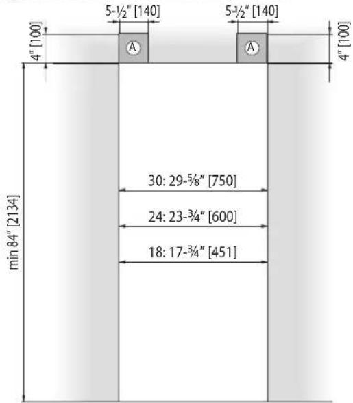
Area to be left clear for the anti-tip brackets
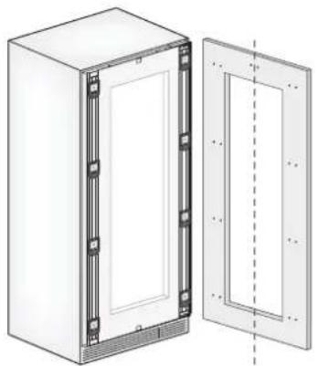
INSTALLATION CUT-OUT - KRC, KFC, KWC, KRW-OV MODELS WITH OVERLAY
18", 24" AND 30" COLUMN REFRIGERATORS AND FREEZERS
18", 24"WINE COLUMN AND 24"REFRIGERATOR WITH WINE
| Cut-out Height Cut-out Width | |||
| 18" models 84" [213] | 4 mm] 18" models 17-3/4" | [451 mm] | |
| 24" models 84" [213] | 4 mm] 24" models 23-3/4" | [600 mm] | |
| 30" models 84" [213] | 4 mm] 30" models 29-5/8" | [750 mm] | |
| Door Swing Clearance Width | |||
| 18" models 40-5/32" | [1020 mm] 18" models 17 | -11/16" [449 mm] | |
| 24" models 45-29/32" | [1166 mm] 24" models 23-5/8" [599 mm] | ||
| 30" models 51-9/16" | [1310 mm] 30" models 29 | -1/2" [749 mm] | |
| Door Opening Angle 105° | |||
| Height 83-1/2" [2120 mm] | 1" [25 mm] | ||
| Depth with door (without panel) 24-1/4" | [615 mm] | ||
Area to be left clear for the anti-tip brackets
Images show unit WITHOUT overlay panel attached.
PREPARING THE INSTALLATIONPREPARING THE INSTALLATION
Transport to Installation site and unpackingTransport to installation site and unpacking
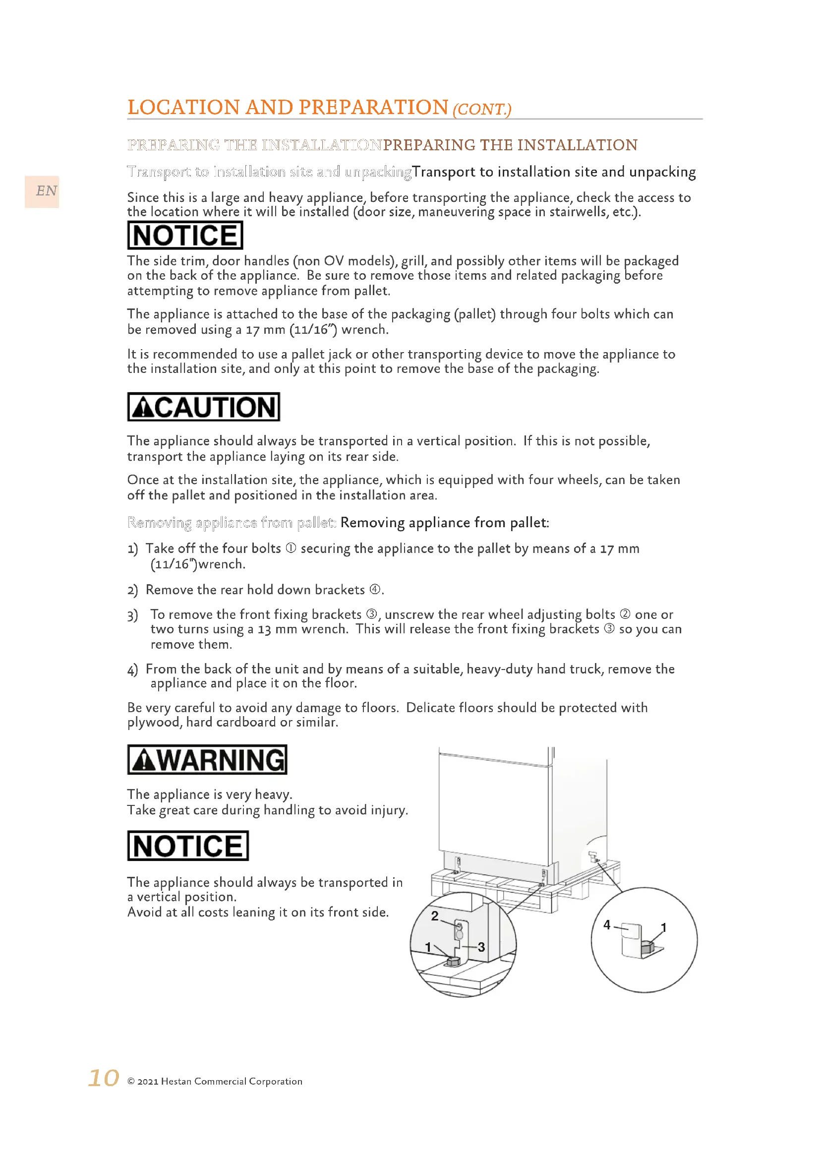
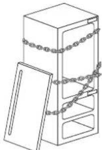
Since this is a large and heavy appliance, before transporting the appliance, check the access to the location where it will be installed (door size, maneuvering space in stairwells, etc.).
NOTICE
The side trim, door handles (non OV models), grill, and possibly other items will be packaged on the back of the appliance. Be sure to remove those items and related packaging before attempting to remove appliance from pallet.
The appliance is attached to the base of the packaging (pallet) through four bolts which can be removed using a 17mm (11 / 16^ ) wrench.
It is recommended to use a pallet jack or other transporting device to move the appliance to the installation site, and only at this point to remove the base of the packaging.
CAUTION
The appliance should always be transported in a vertical position. If this is not possible, transport the appliance laying on its rear side.
Once at the installation site, the appliance, which is equipped with four wheels, can be taken off the pallet and positioned in the installation area.
Removing appliance from pallet: Removing appliance from pallet:
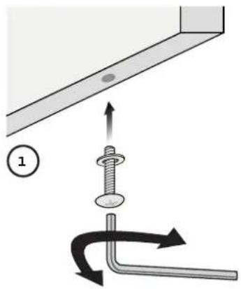
1) Take off the four bolts ① securing the appliance to the pallet by means of a 17 mm (11/16")wrench.
2) Remove the rear hold down brackets ④.
3) To remove the front fixing brackets ③ , unscrew the rear wheel adjusting bolts ② one or two turns using a 13 mm wrench. This will release the front fixing brackets ③ so you can remove them.
4) From the back of the unit and by means of a suitable, heavy-duty hand truck, remove the appliance and place it on the floor.
Be very careful to avoid any damage to floors. Delicate floors should be protected with plywood, hard cardboard or similar.
WARNING
The appliance is very heavy.
Take great care during handling to avoid injury.
NOTICE
The appliance should always be transported in a vertical position.
Avoid at all costs leaning it on its front side.

Additional included items Additional included items
Several items are shipped inside the appliance. These include:
- Manuals
Wood panels installation hardware (-OV models)
Water connection fitting, water filter (models with ice maker) - Anti-tip brackets
- Care items - polishing cloth and/or sponge.
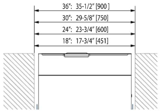
CUT-OUT DIMENSIONS AND INSTALLATION METHODS - FLUSH
| Models | Cut-out | Panel Width |
| KRB36 Models | 35-1/2" [900 mm] | 35-1/4" [897 mm] |
| 30" Columns (KxCx30) | 29-5/8" [750 mm] | 29-3/8" [747 mm] |
| 24" Columns and Wine (KxCx24, KRWx24) | 23-3/4" [600 mm] | 23-1/2" [597 mm] |
| 18" Columns (KxCx18) | 17-3/4" [451 mm] 17 | 1/2" [445 mm] |
A A
B
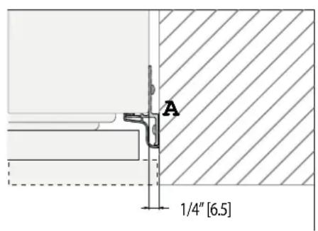
A Lateral/side connection kit (included accessory) (SEE NOTE ON Page 27)
AKRLJK (for KRB, KRC, KFC, KWC and KRW Models)
AKRLJKP (for KRP Models)
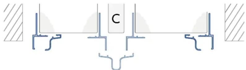
B Central connection kit, required when joining 2 units
(not included - must be ordered as a separate accessory)
AKRCJK-OV for KRB, KRC, KFC, KWC and KRW Models with overlay front
AKRCJK for KRB, KRC, KFC, KWC and KRW Models with stainless or colored front
AKRCJKP for KRP Models
C Anti-Condensation kit # AKRACPP, required when joining two KRP units.
(not included - must be ordered as a separate accessory)
EN
CUT-OUT DIMENSIONS AND INSTALLATION METHODS - NON-FLUSH
If installing non-flush, the same side trim is used and the same cutout width is required.
A: Lateral / side connection kit (SEE NOTE ON PG. 27)
CONNECTIONS
ELECTRICAL AND WATER CONNECTION ELECTRICAL AND WATER CONNECTION
CAUTION
Do not use extension cords and/or multiple adapters for the power supply connection.
Do not use extension cords or adapters.
The built-in Hestan filter cannot make any water safe to drink, it must be used with water that is already suitable for human consumption.
NOTICE
Water supply alarm: Water supply alarm:
If the water supply must be turned off after the the appliance is fully installed, connected to the water supply (if applicable) and operational, touch the On/Off switch to turn the unit off first to avoid a 'NO WATER IN' alarm.
The appliances are delivered from the factory for operation at 110V-120V AC - 60Hz (US and Canada). They are provided with a suitable supply cord and plug to be connected to an appropriate 15A socket (US and Canada) provided with an effective grounding.
A circuit breaker should also be installed and should be easily accessible so that it can be easily switched off before performing any installation or maintenance.
To connect to the water supply system (for appliances equipped with ice makers) a 1/4'' water line with accessible shut-off valve must be supplied.
The appliance is provided with a water adapter elbow which is suitable for high water pressure and complies with appropriate regulations. The water filter cartridge provided with the appliance should be installed according to the accompanying instructions.
KRP, KRB models have the water filter mounted above the refrigerator compartment above the glass panel.
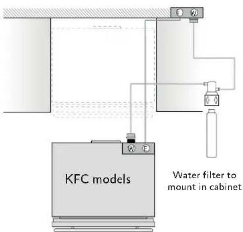
KFC models are provided with a water filter assembly which must be mounted outside the unit.
NOTICE
Use only the new adapter which is supplied with the appliance. The solenoid connection on the appliance looks like 3 / 4'' diameter but is metric threaded. A standard garden hose threaded connector such as a braided stainless hose found at typical hardware stores will strip or damage the solenoid threads. Use only the supplied 1 / 4'' quick connect elbow adapter for connecting a 1 / 4'' copper or polyethylene source water line to the appliance.
Electrical cord length: 78 - 3 / 4'' [2000 mm]
Water connection line length: 98 - 3 / 8^ [2500 mm]
See following page for additional information.
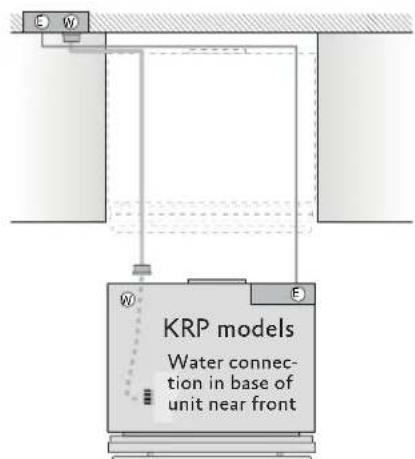
KRP MODELSKRP MODELS
Connect as follows: Connect as follows:
Unwind the electric cord and connect it directly to the wall socket.
Observe the information display. If the appliance is not in Stand-by condition or if any lights are on, press the On/Off button for three seconds to switch it off.
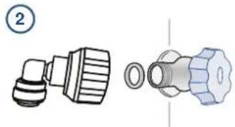
Connect the water line to the threaded connection at the base of the unit. (1)
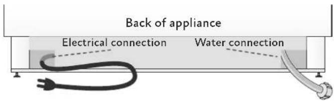
Fit the other end of the hose (2) to the water valve, use the gaskets provided in the Owner's Kit.
Firmly tighten by hand - a tool/wrench should not be needed to make a proper seal.
Turn on the water and ensure all connections are not leaking prior to pushing the unit into the opening.
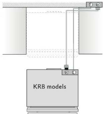
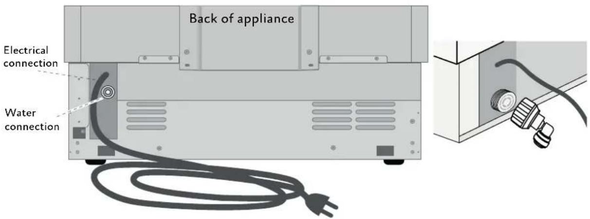
ALLOTHERMODELSALLOTHERMODELS
Connect as follows: Connect as follows:
Unwind the electric cord and connect it directly to the wall socket.
Observe the information display. If the appliance is not in Stand-by condition or if any lights are on, press the On/Off button to switch it off.
Push the 1/4'' source waterline fully into the elbow connector then thread the elbow adapter to the solenoid at the back of the appliance.
Firmly tighten by hand - a tool or wrench should not be needed to make a proper seal.
Turn on the water and ensure all connections are not leaking prior to pushing the unit into the niche.
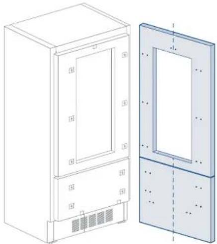
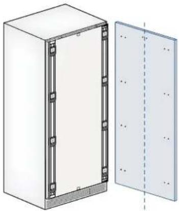
DOOR AND DRAWER OVERLAY PANEL PREPARATION DOOR AND DRAWER OVERLAY P
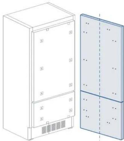
Decorative panels:Decorative panels:
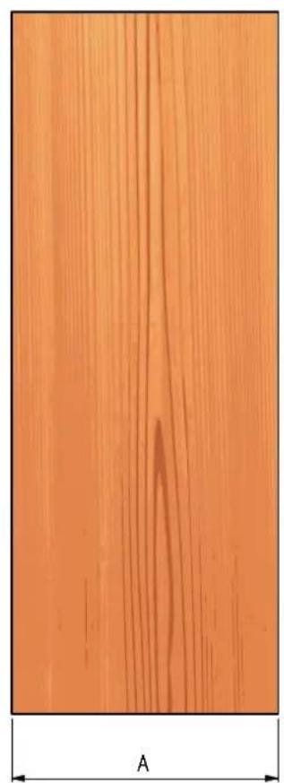
The dimensions of the panels are indicated in the table and drawings on following pages.
To align panels with other kitchen structures, sizes can be adjusted if the door panel needs to be higher than the upper edge of the refrigerator door, and/or the drawer panel needs to lower than the edge of the drawer.
The panels must be mounted using special braces which attach to adjustable devices provided on the door and drawer and with brackets that anchor and adjust the panel's vertical direction.
Braces, brackets and fixing screws are provided with the appliance and must be applied to the panel as indicated.
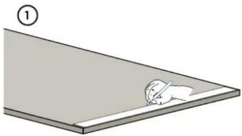
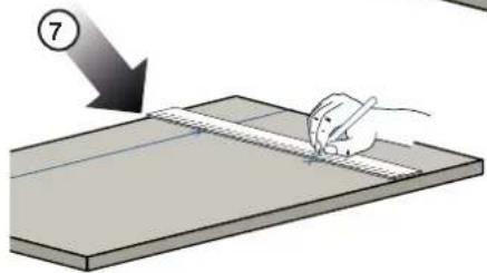
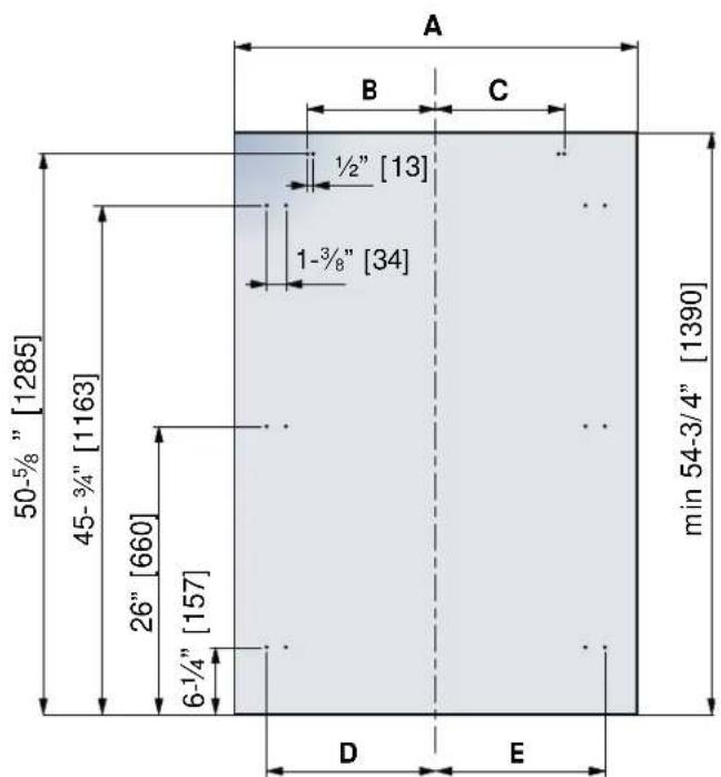
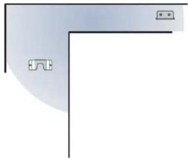
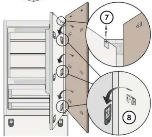
Layout procedure: Layout procedure:
To prepare the panels to be mounted on the appliance, follow these steps, working on the back of the panel.
Door Panel
1) Trace a line dividing the panel width in half. (1)
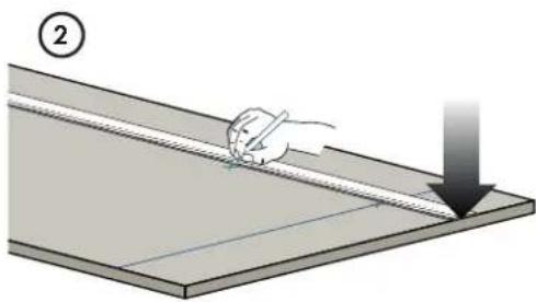
2) Starting from the bottom edge of the panel, mark the positioning of the brackets. (2)
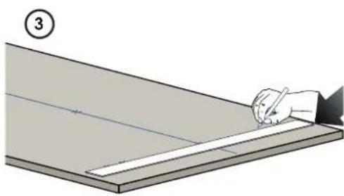
3) Following the corresponding table, mark the external and then the internal hole. (3)
EN
EN
DOOR AND DRAWER OVERLAY PANEL PREPARATION (continued)
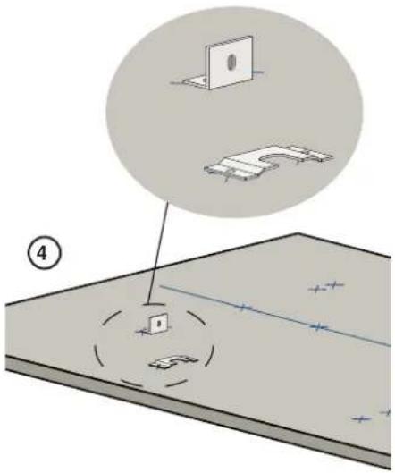
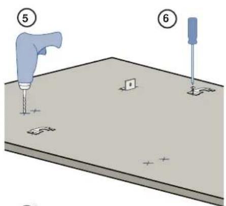
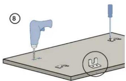
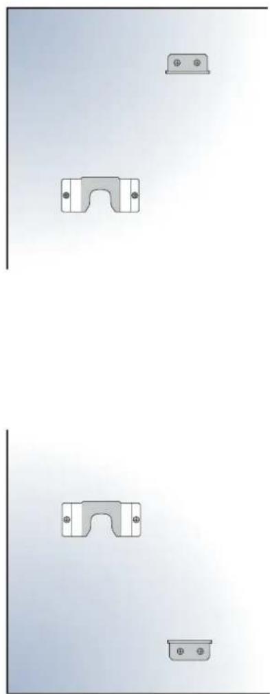
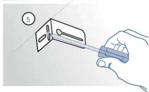
Mounting the Brackets Mounting the Brackets
4) Position the brackets on each set of marks to make sure they are aligned. (4)
Note that the support bracket mounts with its flange toward the top of the door.
If necessary, drill starter holes in the panel. (5) (Use a drill stop to avoid drilling through or damaging the finish surface.)
NOTICE
The installation kit includes 5/8'' screws. If the panel isn't substantially thicker than 5/8'' , you'll need shorter screws.
1) Screw the brackets in place. (6)
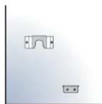
DrawerPanelDrawer Panel
When preparing the Printer Panel, follow the same instructions as per the door panel, but make sure measurements are taken starting from the top edge. (7)
The support bracket faces the opposite way from the door panel bracket. (Compare images 4 and 8.)
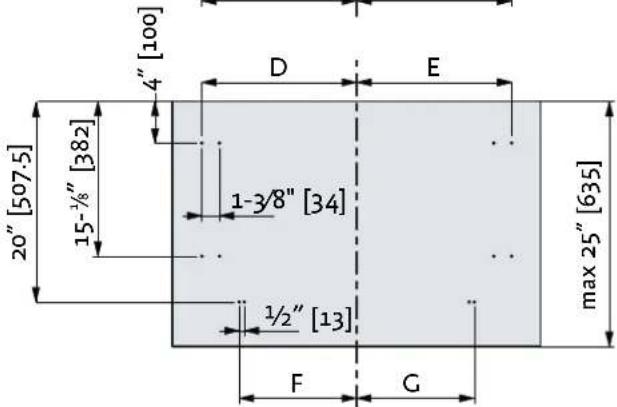
PANEL DIMENSIONS KRB - OV PANEL DIMENSIONS KRB - OV
| KRBx36-OV | ||
| Hinge Left | Hinge Right | |
| A | 35-1/4" [897] | 35-1/4" [897] |
| B | 14" [355.5] | 10-1/4" [261] |
| C | 10-1/4" [261] | 14" [355.5] |
| D | 16-1/2" [418] | 15-1/4" [386] |
| E | 16-1/2" [418] | 15-1/4" [386] |
| F/G | 14" [354.5] | 14" [354.5] |
EN

EN
PANEL DIMENSIONS KRW - OVPANEL DIMENSIONS KRW - OV
| KRWx24-OV MODELS | ||
| Hinge Left Hinge Right | ||
| A | 23-1/2" [597] | 23-1/2" [597] |
| D | 10-7/8" [276.5] | 9-3/8" [236.5] |
| E | 9 3/8" [236.5] | 10-7/8" [276.5] |
| F / G | 8" [203.5] | 8" [203.5] |
| H | 10-5/8" [270.5] | 9-1/8" [230.5] |
| I | 9-1/8" [230.5] | 10-9/8" [270.5] |

PANEL DIMENSIONS KRC - OV, KFC - OVPANEL DIMENSIONS KRC - OV, KFC - OV
See "PANEL DIMENSIONS KRW - OV" on page 18 for KRW models.
See "PANEL DIMENSIONS KWC - OV" on page 20 for KWC models.
| 30"-OV Column Models | 24"-OV Column Models | 18"-OV Column Models | ||||
| Hinge Left | Hinge Right | Hinge Left Hinge Right | Hinge Left Hinge Right | |||
| A | \( 29^{-\frac{3}{8}} \) [747] | \( 29^{-\frac{3}{8}} \) [747] 23 | \( 23^{-\frac{1}{2}} \) [597] | \( \frac{1}{2} \) [597] | \( 17^{-\frac{5}{8}} \) [447] | \( 17^{-\frac{5}{8}} \) [447] |
| B | \( 13^{-\frac{1}{2}} \) [343] | \( 13^{-\frac{1}{2}} \) [343] | \( 10^{-\frac{7}{8}} \) [276.5] | \( 10^{-\frac{1}{2}} \) [268] | \( 7^{-\frac{7}{8}} \) [200] | \( 7^{-\frac{7}{8}} \) [200] |
| B | \( 13^{-\frac{1}{2}} \) [343] | \( 13^{-\frac{1}{2}} \) [343] | \( 10^{-\frac{1}{2}} \) [268] | \( 10^{-\frac{7}{8}} \) [276.5] | \( 7^{-\frac{7}{8}} \) [200] | \( 7^{-\frac{7}{8}} \) [200] |
EN
PANEL DIMENSIONS KWC - OV PANEL DIMENSIONS KWC - OV
| MODEL KWCx24-OV | MODEL KWCx18-OV | |||
| Left Hinge Right | Hinge | Left Hinge Right | Hinge | |
| A | 23-1/2" [597] | 23-1/2" [597] | 17-5/8" [447] | 17-5/8" [447] |
| B | 10-7/8" [276.5] | 10-7/2" [268] | 7-7/8" [200] | 7-7/8" [200] |
| B | 10-7/2" [268] | 10-7/8" [276.5] | 7-7/8" [200] | 7-7/8" [200] |
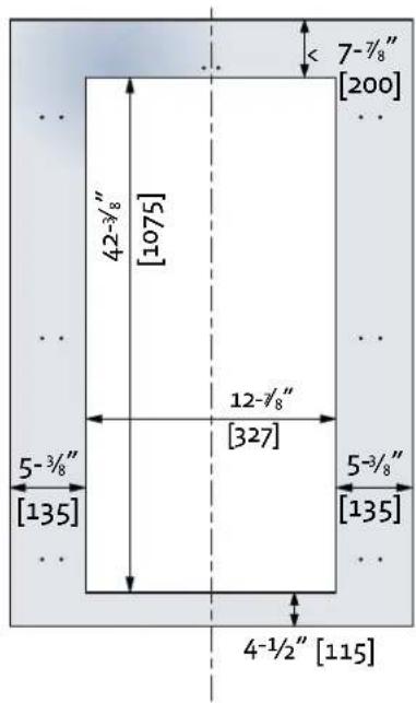
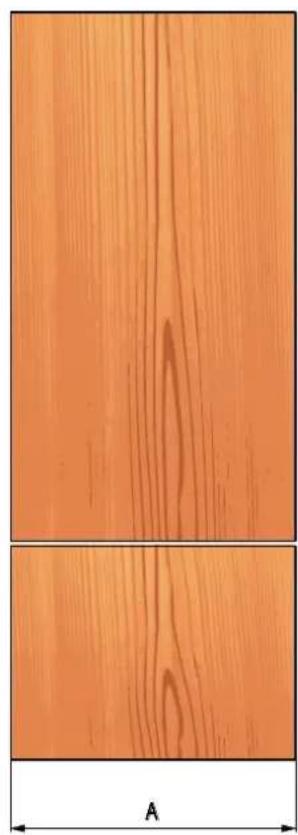
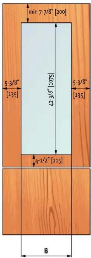
PANEL DIMENSIONS KRB 36-OV AND KRW 24-OVPANEL DIMENSIONS KRB 36-OV AND I
Panels can have thickness ranging between 3/4'' [18 mm] and 1-1/8'' [28 mm].
Door panels can have a maximum weight 51 lbs [23 kg] and drawer panels may be a maximum weight of 25 lbs [11 kg].
Exceeding these weights could void your warranty for any service issues which can be attributed to overweight panels.
The hinge mechanism on Hestan refrigerators is considered to be 'Zero-clearance'. The door and drawer widths specified below assume the minimum niche width is being used and a 1/8'' [3.5 mm] reveal is desired around the panels. Adjust your panel dimensions accordingly to your own design criteria considering your niche width and your reveal. Minimum reveal / gap should not be less than 1/16'' [1.5 mm].
| Models | Door/Drawer Width A | Door Cutout Width B |
| KRBR/L36-OV | 35-1/4" [897] | N/A |
| KRWR/L24-OV | 12-7/8" [327]23-1/2" |
Example:
84" cut-out height 36" cut-out width
4" toe kick height
1 / 8'' gap desired all around
Door panel: Width: 35-3/4" Height: 54-3/4"
Determining drawer panel sizes:
Width: 35 · 3 / 4
Height: 84^ - 1 / 8^ - 543 / 4^ - 1 / 8^ - 4^ = 25^
If you want a 6'' toe kick height with 1/8'' gaps then your
bottom drawer panel height would be 23'
EN
PANEL DIMENSIONS KFC - OV, KRC - OV AND KWG - OV
Panels can have thickness ranging between 3/4'' [18 mm] and 1-1/8" [28 mm].
Door panels can have a maximum weight 51 lbs [23 kg] and drawer panels may be a maximum weight of 25 lbs [11 kg].
Exceeding these weights could void your warranty for any service issues which can be attributed to overweight panels.
The hinge mechanism on Hestan refrigerators is considered to be 'Zero-clearance'. The door and drawer widths specified below assume the minimum niche width is being used and a 1/8'' [3.5 mm] reveal is desired around the panels. Adjust your panel dimensions accordingly to your own design criteria considering your niche width and your reveal. Minimum reveal / gap should not be less than 1/16'' [1.5 mm].
| Models | Door/Drawer Width A | Door Cutout Width B |
| KFC, KRCx30-OV | 29-3/8" [747] | N/A |
| KFC, KRCx24-OV | 23-1/2" [597] | N/A |
| KWCx24-OV 23-1/2" [597] | 12-7/8" [327] | |
| KFC, KWCx18-OV | 17-5/8" [447] 6-7/8" | 177] |
MOUNTING HANDLES ON OVERLAY PANELS MOUNTING HANDLES ON OVERLAY PANI
Handles must be mounted on the panels before the panels are applied to the fridge.
EN
Place the handle on top of the holes and insert the screws through the panel and into the handle support.
Handles not provided with Overlay (OV) Models (sample handle shown)
Accurately measure the distance between hole centers for correct dimensions to apply before drilling the mounting holes in your panels.
EN
PREPARING DOOR AND DRAWER FOR OVERLAY PANELSPREPARING DOOR AND DRA
The adjusting screws and hanger bolts must be threaded into place in the door (and drawer, if applicable) before applying the decorative panels.
Install the vertical adjustment screws into the bottom of the drawer (if applicable) 2-3 turns deep. The vertical adjustment screws for the door panel are installed after applying the door panel.
Install one hanger bolt into each recess - only 2-3 turns deep.
Install one depth adjustment screw into the holes above or below each recess - the wrench opening goes in first so adjustments can be made from the appliance side of the door. These should be screwed in almost flush to the face of the gasket surrounding them.
The depth adjustment screws can be started and screwed in much of the way by hand. If needed, they can be finished using a 4mm allen wrench from the inside of the door or drawer gently pull the door gasket aside to reveal the screw hole.
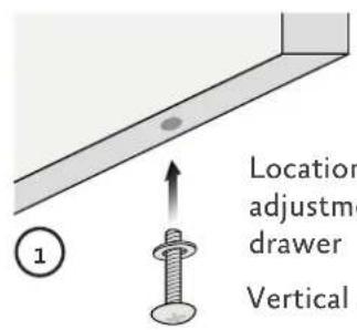
Location of vertical adjustment screws in drawer
Vertical adjustment screw
NOTE: Vertical adjustment screws for door are installed after hanging panel on door.
Depth adjustment screw: Install with socket toward appliance
Hanger bolt
(4) Depth adjust screws - these adjust spacing between door and panel
(5) Hanger bolts - these secure the panel
MOUNTING OVERLAY PANELS TO DRAWERMOUNTING OVERLAY PANELS TO DRAWEI
Once all brackets and small brackets have been applied to the panels, you can begin installing the bottom drawer panel.
EN
1 Leave the vertical adjustment screws just a few turns in.
Mount the bottom drawer panel: Make sure the height adjustment screw heads are under the adjusting brackets. Then fit the attachment brackets over the hanger bolts.
Final adjustment must be done after the appliance is in place and the side trim mounted.
Use the height adjustment screws to align panels to adjacent cabinets.
The panel has some adjustment sideways when the hanger bolts are slightly loose.
Depth alignment: working from the inside of the drawer, use the depth adjusting screws (4) to push the panel away from the door as needed, and snug the hanger bolts (5) to secure the panel in place.
MOUNTING OVERLAY PANELS TO DOORMOUNTING OVERLAY PANELS TO DOOR
Hook the panel to the hanger bolts starting from the top aligning brackets (6).
After the panel is hooked on all hanger bolts, install the two vertical adjustment screws. See (9) below.
At this point, alignment between the panel and adjacent cabinets can be adjusted using the alignment brackets and brackets (7) and (8).

Vertical alignment: tighten or loosen the screws in the brackets to raise or lower the panel. (9)
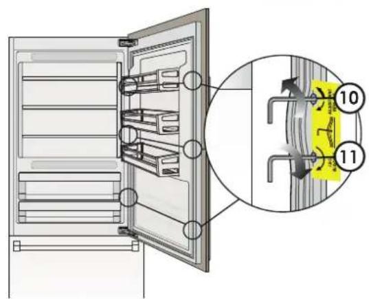
Depth alignment: working from the inside of the door, after lifting up the magnetic seal, adjust the panel position so it is closer to or further away from the door using (10) and then fix the panel in position using (11)
INSTALLING TWO OR MORE UNITS TOGETHER - TOTAL OPENING WIDTH
The best practice for planning and installing built-in units together is to combine the actual widths of each unit, and add another 1/8 [3 mm] to get the total opening width. When placed next to each other, the side profile trims are used to hold the units together (discussed on the next page).
| MODEL SIZE | ACTUAL WIDTH |
| 36" 35-3 | /8" [899 mm] |
| 30" 29-1 | /2" [749 mm] |
| 24" 23-5 | /8" [599 mm] |
| 18" 17-1 | 1/16" [449 mm] |
EXAMPLE (30^ + 24^ units)-The 30^ model has an actual width of 29 - 1 / 2'' [749 mm], and a 24^ model has an actual width of 23 - 5 / 8'' [599 mm]. Added together:
$$ 2 9 - 1 / 2 ^ {\prime \prime} + 2 3 - 5 / 8 ^ {\prime \prime} + 1 / 8 ^ {\prime \prime} = 5 3 - 1 / 4 ^ {\prime \prime} [ 1 3 5 1 m m ] $$
EXAMPLE (30'' + 24'' + 36'' units) - The 30'' model has an actual width of 29 - 1 / 2'' [749 mm], a 24'' model has an actual width of 23 - 5 / 8'' [599 mm], and a 36'' model has an actual width of 35 - 3 / 8'' [899 mm].
$$ 2 9 - 1 / 2 ^ {\prime \prime} + 2 3 - 5 / 8 ^ {\prime \prime} + 3 5 - 3 / 8 ^ {\prime \prime} + 1 / 8 ^ {\prime \prime} = 8 8 - 5 / 8 ^ {\prime \prime} [ 2 2 5 0 \mathrm {m m} ] $$
INSTALLING TWO OR MORE UNITS TOGETHER-CONNECTIONS
Installing two or more units as built-ins next to each other requires a Central Connection Kit.
Not included - must be ordered as a separate accessory
AKRCJK (for KRB, KRC, KFC, KWC and KRW Models in Stainless Steel or color)
AKRCJK-OV (for KRB, KRC, KFC, KWC and KRW overlay models)
AKRCJKP (for KRP Models)
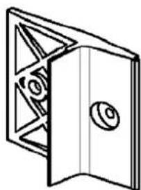
The appliance comes with side connectors on each side. The connector kit provides connectors for the rear of the units, fasteners, and a trim cap for the center junction.
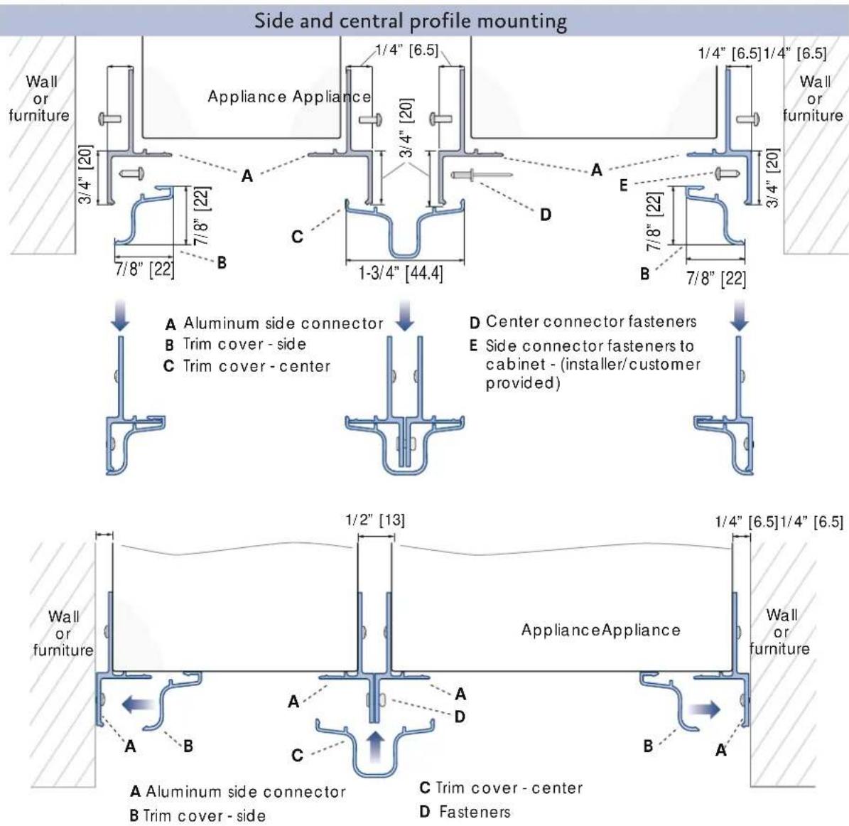
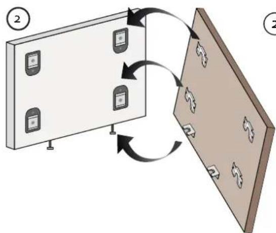
NOTE: The aluminum side connector (item A above) is typically pre-installed on all refrigeration units at the factory. In mid-2019, a design change was made and the aluminum parts were replaced by a kit included with the unit. The kit contains 10 plastic side connectors that look like this.
Follow the instructions included with the kit to attach these new side connectors.
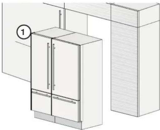
INSTALLING TWO OR MORE UNITS TOGETHER INSTALLED TWO OR MORE UNITS TO
Position the two units so that, when joined, they can be rolled into their final position.
1) For KRP units, place the anti-condensation insulator according to its directions.
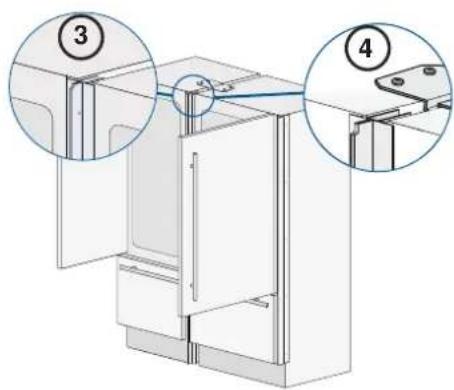
2) Place the units side by side, and check leveling. The two units must be at the same height before connecting. (Item 3, this page) The side connectors should just touch along their length.
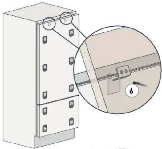
3) At the rear, mount the joining brackets to one unit, then the other. (Item 2, this page)
4) The top may also require a connector. Install if required/provided. (Item 4, this page)
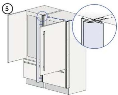
5) At the front, attach the aluminum center connectors together using the fasteners provided. (Items D, previous page)
6) Snap the center trim cover into place. (Item 5, this page)
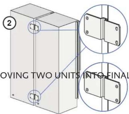
MOVING TWO UNITS INTO FINAL POSITIONMOVING TWO UNITS INTO FINAL POSITION
Make sure the side connectors will fit the cutout width. See "CHECK/ADJUST SIDE TRIM" on page 30.
The procedure is the same as for a single unit. See following page.
EN
MOVING SINGLE UNIT INTO POSITIONMOVING SINGLE UNIT INTO POSITION
Side connectors with decorative trim pieces are provided to secure the appliance to adjacent cabinetry.
Make sure the side connectors will fit the cutout width. See "CHECK/ADJUST SIDE TRIM" on page 31.
All but KRP: The unit does not need a ventilation shaft in the cabinet for cooling.
KRP: See "INSTALLATION CUT-OUT - KRP MODELS" on page 5 for ventilation requirements.
Always mount front panels on the door and drawer before pushing the unit into its final position inside the enclosure.
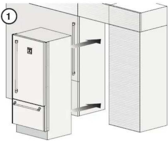
1) Move the unit into its final position
2) Check the leveling of the appliance, adjusting the feet and wheels to correct it if necessary.
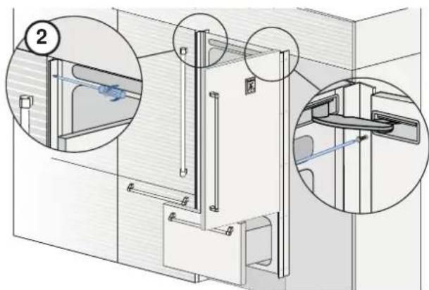
3) Secure the appliance to the adjacent cabinets using the side profiles. (2) To make this operation easier keep the door and the drawer open.
4) Mount the trim covers (3) by first inserting them laterally then pushing firmly until a "click" is heard.

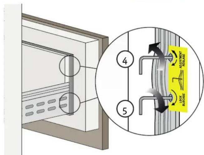
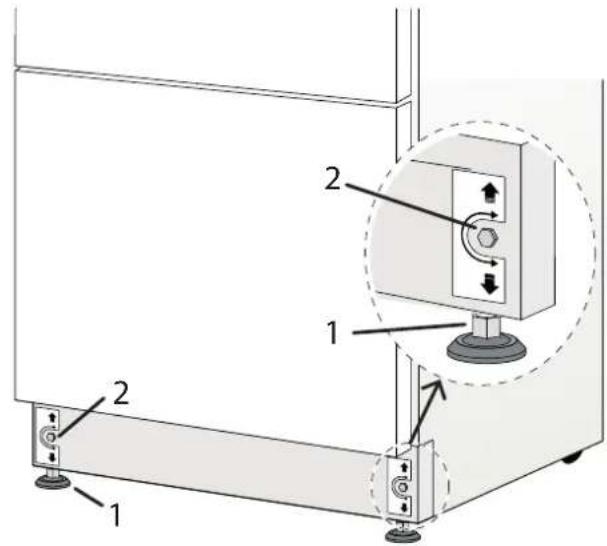
LEVELING THE APPLIANCE LEVELING THE APPLIANCE
Adjust the appliance level by means of the front leveling feet and the rear adjustable wheels.
Leveling must be done after the appliance has been moved into place.
Level as follows: Level as follows:
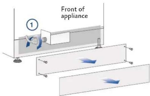
1) Remove the bottom grille if necessary (it is kept in position by magnets)
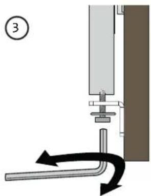
2) Adjust the front using the leveling feet (1) by means of a 17mm (or 11/16'' ) open-end or adjustable wrench.
3) Adjust the height of the rear by turning the front adjusting bolts (2) clockwise or counterclockwise as required.
4) Reinstall the grill.
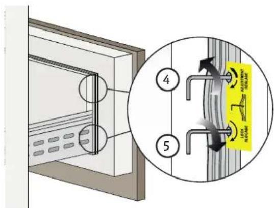
The standard side trim fits an opening of the specified dimensions, as listed on page 5 and following pages.
If the cutout is a bit wider or not perfectly square, the trim can be adjusted to fit.
The suggested method is to use spacers between the appliance and the trim strip under each of the five screws securing each trim strip. Flat washers can be used as spacers, select thicknesses as appropriate.
This adjustment should be done before any decorative panels are mounted to the doors.
TRIM FOR INSTALLING TWO OR MORE UNITS TOGETHER
When installing units side-by-side, a special trim kit must be used on the facing sides. See "INSTALLING TWO OR MORE UNITS TOGETHER" on page 28.
ANTI-TIP HARDWAREANTI-TIP HARDWARE
The anti-tip hardware installation is detailed on page 32, and must be completed after the appliance is in place and has been leveled.
However, you may wish to make the preparations before mounting any decorative panels.
EN
ANTI-TIP SAFETY ANTI-TIP SAFETY
WARNING
To avoid danger of the appliance tipping over it is mandatory to secure the appliance to the wall by means of the two provided brackets, or if the brackets are not accessible, by means of a wood block at the rear wall of the enclosure.
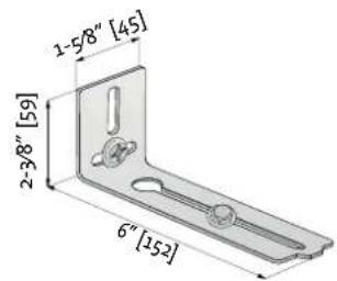
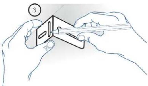
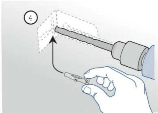
MOUNTING SAFETY ANTI-TIP BRACKETS - All except KRP series
When using the anti-tip brackets, they should be applied as illustrated using the provided screws and wall anchors.
1) Find the mounting holes on top of the appliance, and determine how the bracket must align with the wall.
2) Mark the wall where the holes are needed.
3) Drill the wall with an 5 / 16'' [8 mm] bit and insert the wall anchor.
4) Position the bracket and secure it first to the appliance, then to the wall.
In addition, it is suggested:
- The side trim pieces on both sides must be secured to the unit with the provided screws
- The side trim pieces must be screwed to the cabinets at all provided attachment points.
- The cabinet must be securely attached to the wall to assure the stability of the appliance.
When two units are installed together, the anti-tip brackets are required for each of them.
In addition, the correct joining kit must be installed and the units must be secured to the adjoining cabinets by means of the side trim pieces, as above.
1
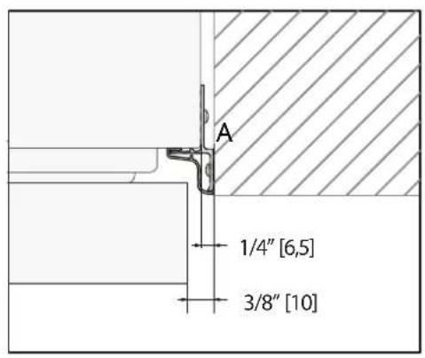
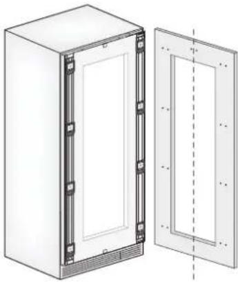
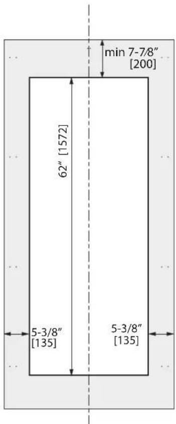
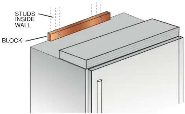
REAR WALL BLOCKING - All unitsREAR WALL BLOCKING - All units
If your cabinetry/enclosure makes the anti-tip brackets inaccessible, you may attach wood blocking at the rear wall of the enclosure. Place the block about 1 / 8 - 1 / 4 [3-6mm] above the final height of the rear of the fridge, and attach with appropriate fasteners into the wall studs. Drywall anchors / toggle bolts are not recommended and can rip out of the wall.
When the fridge is moved into its final position and the legs adjusted, the top of the fridge can make contact with the wood block, thus securing the unit from tipping.
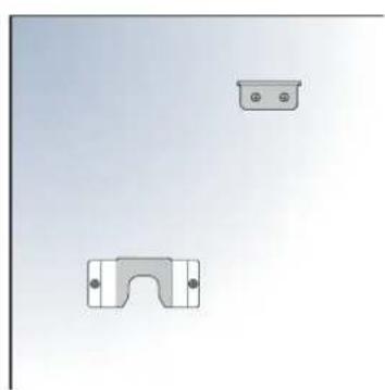
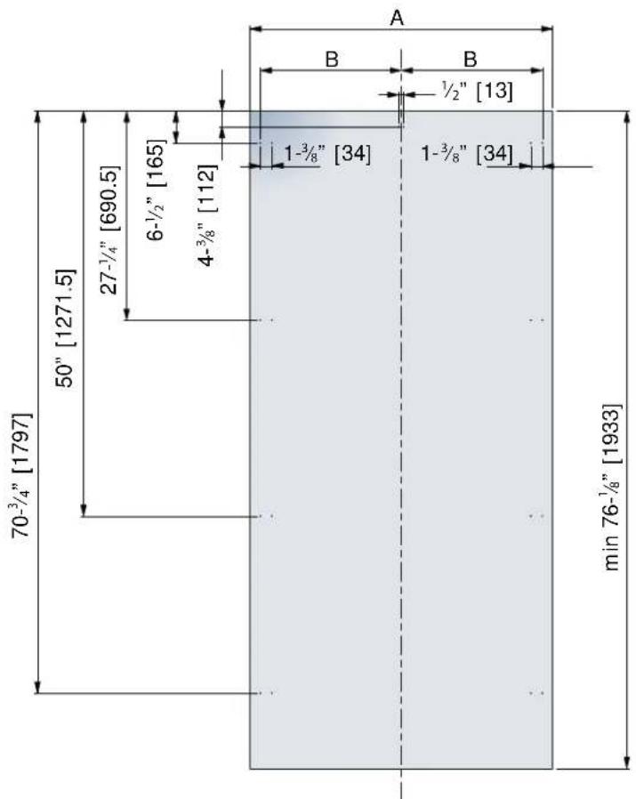
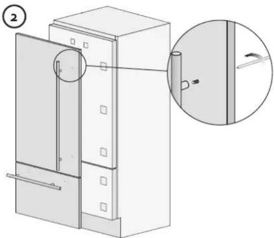
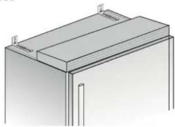
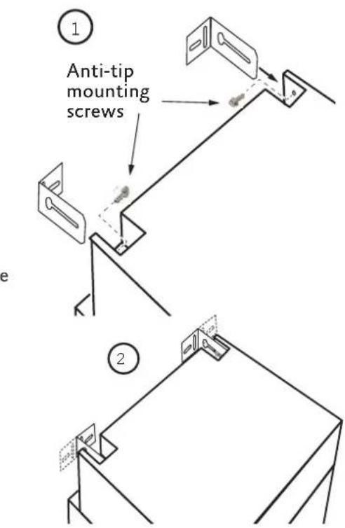
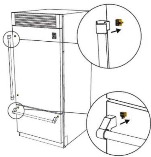
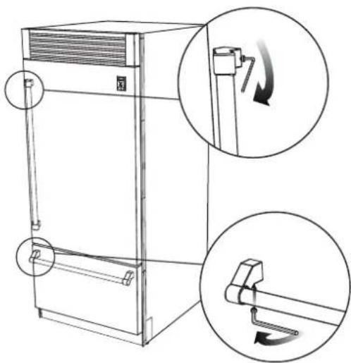
MOUNTING SAFETY ANTI-TIP BRACKETS - KRP series
To avoid danger of the appliance tipping over it is mandatory to secure the appliance to the wall by means of the two provided brackets.
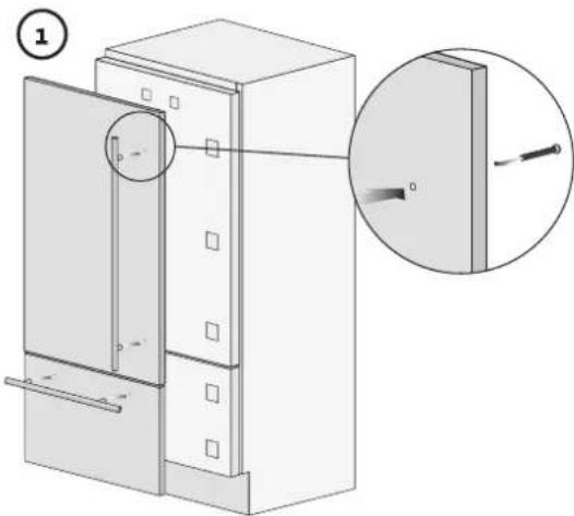
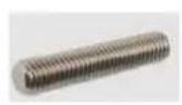
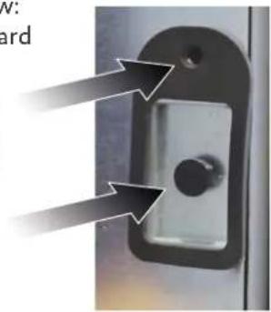
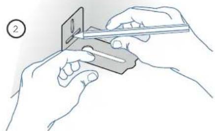
1) The appliance has one screw in place where each bracket will attach. (See figure to right.) Remove the screws and set aside.
2) Determine location of brackets and mark the wall accordingly. Note that the brackets can be installed facing in or out, as preferred.
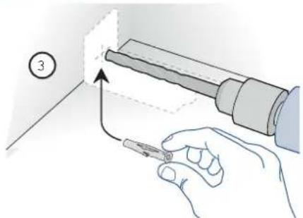
3) Roll the unit away from the wall, and mark the hole locations.
4) Drill anchor holes and install the anchors.
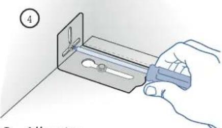
5) Mount the bracket to the wall, then roll the appliance into position and attach the bracket to the appliance using the screws saved from (1) above.
In addition, it is suggested:
- The side trim pieces on both sides must be secured to the unit with the provided screws
- The side trim pieces must be screwed to the cabinets at all provided attachment points.
- The cabinet must be securely attached to the wall to assure the stability of the appliance.
When two units are installed together, the anti-tip brackets are required for each of them.
In addition, the correct joining kit must be installed and the units must be secured to the adjoining cabinets by means of the side trim pieces, as above..
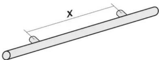
MOUNTING THE HANDLES AND ENDCAPSMOUNTING THE HANDLES AND ENDCAPS
Handles and endcaps are provided with all stainless and color models. Handles are located in protective wrapping, taped to the back of the refrigerator. Remove the handles before moving the refrigerator into its cut-out or opening. Endcaps are located in a cardboard box inside the refrigerator.
It is recommended that two people work together to assemble and apply the handles and endcaps. Follow the steps below to complete the mounting process.
Insert the handle into the endcaps and rotate as needed to align the notch in the tube, with the tab inside the endcap. A light tap with a wood or plastic hammer will help insert the tube fully. Position the endcaps over the supports that are pre-mounted on the door and drawer face.
- Use caution not to scratch the door surface.
It is recommended that one person holds the handle and endcaps in position while the second person inserts the provided set screws used to secure the handle.
The provided set screws are located in the box with the endcaps. Using a 2.5mm hex wrench, insert the set screw into the hole in the endcap and carefully tighten. The endcap is then properly secured to the door/drawer. Repeat this step for the other endcaps.
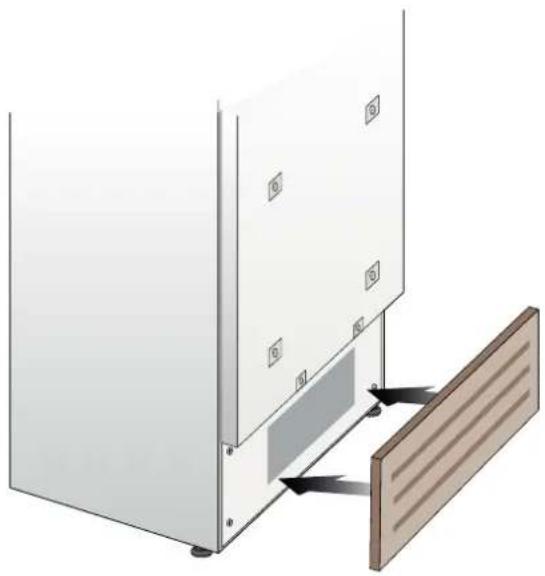
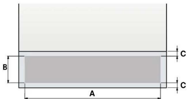
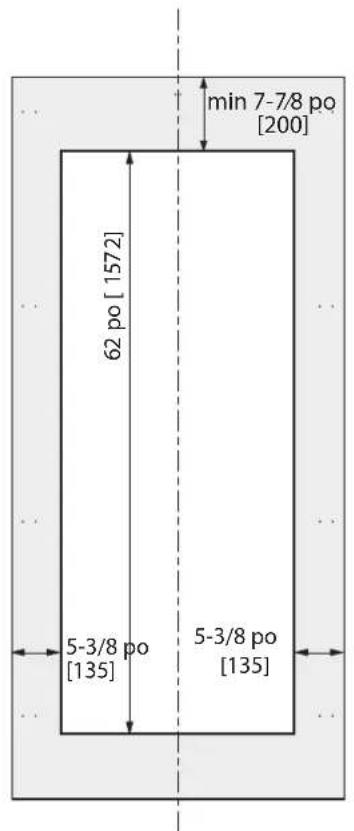
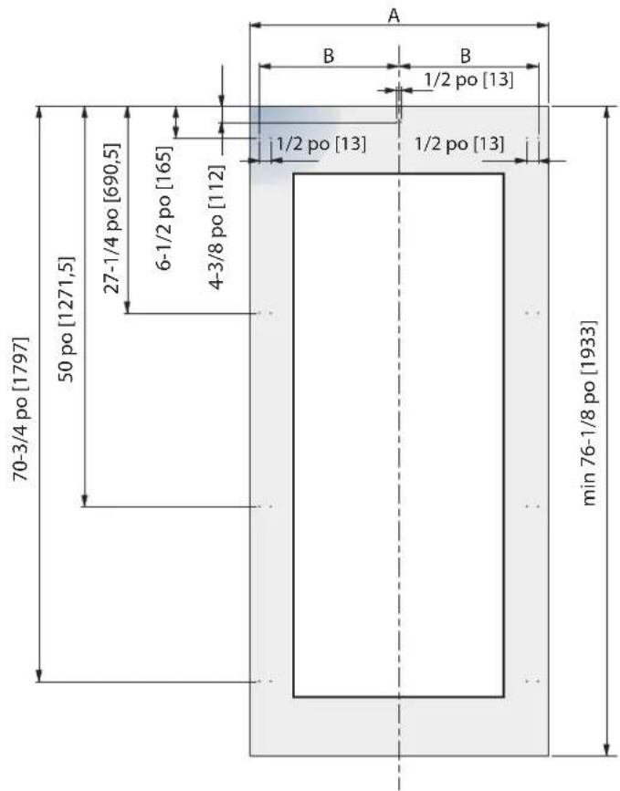
PROPER AIR CIRCULATION (Except KRP) PROPER AIR CIRCULATION (Except KRP)
A forced air system assures ventilation through a grille positioned in the lower front of the unit. If the kitchen design includes an applied toekick, it must have ample openings/slots to maintain proper airflow as illustrated below. Holes/slots can be of any size and shape, provided that the total open area amounts to 50% of the overall size of the decorative cover. In this case, to guarantee proper airflow, it is recommended to remove the front grille included with the unit. The provided grille is secured to the unit with magnetic plates and can be easily removed. The cover should be removed for regular cleaning and removal of dust. If a decorative grille is used, remove the provided grille to allow for proper airflow.
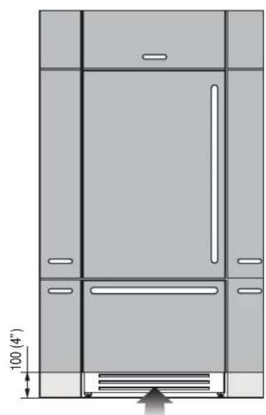
The chart and illustration below provides the proper amount of airflow necessary to maintain. (All models except KRP.)
| 36" Models 18" | Models" Models 24" | Models | ||
| A | 33-7/8" [860 mm] 29-1/8" [740 mm] 22" [560 mm] | 16-1/8" [410 mm] | ||
| B | >4" [100 mm] | |||
| C | 3/8" [10 mm] | |||
EN
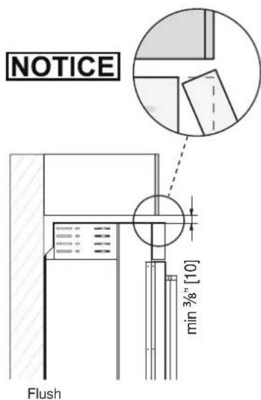
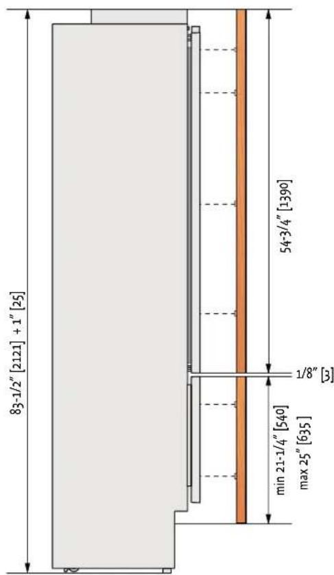
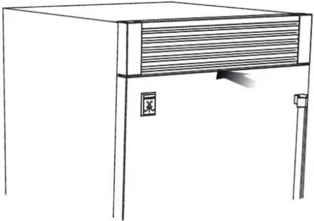
PROPER AIR CIRCULATION (KRF) PROPER AIR CIRCULATION (KRP)
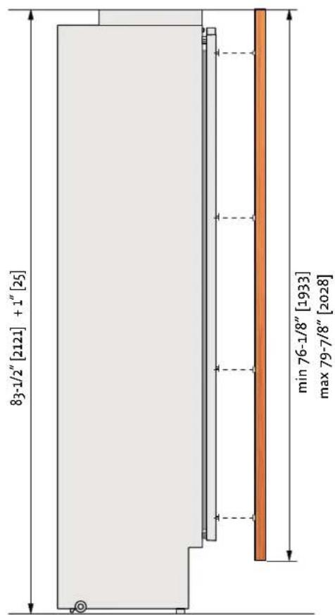
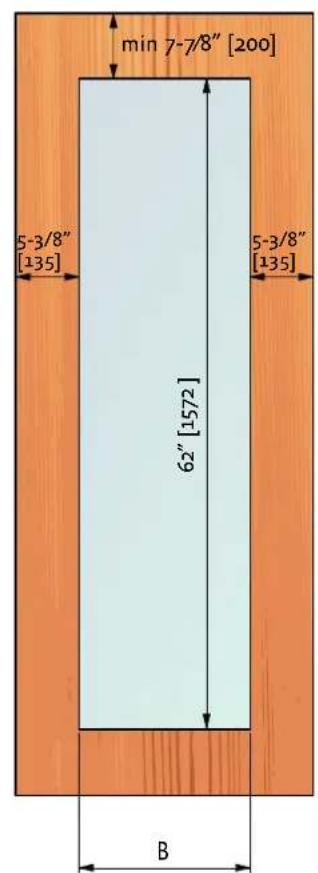
For KRP models, ventilation is provided by a forced air system through a grille in the top of the refrigerator. This open space in the grille must not be restricted by any cover or device that would reduce the proper airflow, as it would reduce product efficiency and increase energy consumption. A vent must be provided at the rear for the air to exit. See page 5 for location and dimensions.
TESTING AND INITIAL START UP
PRETEST CHECKLISTPRETEST CHECKLIST
Check that the connection to the water system does not have any leaks and that the valve is easily accessible.
Check that the electrical connection is correctly installed and that the circuit breaker is identified/marked for later use.
Check that the unit is level and aligns with adjacent cabinets.
Check that the anti-tip brackets are secure, and the side connectors are secure with trim in place.
Check that all adhesive tape and external or internal temporary protective packaging have been removed.
Check the perfect closing of the doors and the smooth sliding of the drawers and shelves.
If the unit has an icemaker, make sure the water filter cartridge is installed. (Unless filtered water is being provided to the unit.)
INITIAL STARTUFINitial STARTUP
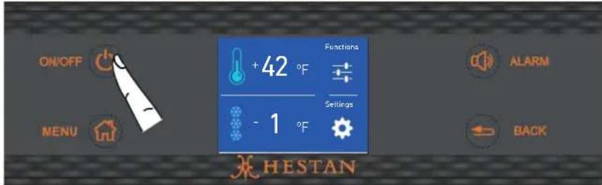
Once the appliance is plugged in, the display will show the Hestan logo, a brief info screen, then go dark.
Turn the appliance ON by pressing the Power button for three seconds. The display will show a Hestan logo, then the message "Initial test, please wait..." for 2-3 minutes. After this phase the compressors will start up and remain on until the default temperature (set at the factory) is reached. Allow ample time for the refrigerator to reach this temperature before loading any items (6-12 hrs). During this time, deactivate any error messages by pressing the Alarm button.
Ice Maker Ice Maker
If the appliance is provided with an ice maker, make sure that the water filter cartridge is properly installed, and the appliance is connected to the water source. Follow these instructions for cleaning / purging the water system for the first time. Place a small tray or bowl inside the ice bin, under the ice maker tray to catch any water during the purge cycle.
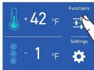
At the Home screen, touch the Functions icon.
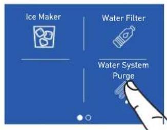
Scroll left, then touch the Water System Purge icon.
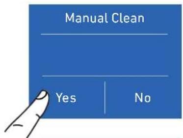
Touch YES to activate the manual cleaning.

Please wait...

Touch the Enter icon to start the cleaning.

Cleaning running...
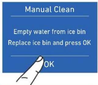
At the end of the cleaning, empty water from ice bin, then press OK.

Wait a few seconds, the home screen will appear. Remove the tray or bowl.
BottomDrawerBottomDrawer
Models KRP, KRB, and KRW have a bottom drawer which defaults to freezer operation. The drawer can also be set to other modes of operation. See the Use and Care manual for more information.
Readiness Readiness
If at first the Start Up message does not appear but other information in the display does appear (such as Fridge too warm, Freezer too warm, or audible signals are heard), the refrigerator has still begun the normal cooling process.
If this is the case, deactivate any audible signals by pressing the Alarm button, close the door and wait until the set temperature is reached.
It is necessary to let the unit reach the correct temperature prior to placing food or beverages in it. (Allow 6-12 hours.)
For further information about the appliance operation, refer to the Use and Care Manual.
PARTS LIST
Please visit the Hestan website to access the parts list for your Hestan Indoor product: www.hestanhome.com.www.hestanhome.com.
SERVICE
All warranty and non-warranty repairs should be performed by qualified service personnel. To locate an authorized service agent in your area, contact your Hestan dealer, local representative, or Hestan Customer Service. Before you call, please have the model number and serial number information ready.
Hestan Commercial Corporation
3375 E. La Palma Avenue
Anaheim, CA 92806
(888) 905-7463
A VERTISSEMENT
LE NON-RESPECT À LA LETTRE DE CES INSTRUCTIONS PEUT CAUSER UN INCENDIE OU UNE EXPLOSION, QUI POURRAIT ENTRAINER DES DOMMAGES MATÉRIELS, DES BLESSURES OU LA MORT.
ACCESSORIES D'INSTALLATION FOURNIS
© 2021 Hestan Commercial Corporation
DECOUPE D'INSTALLATION - MODELES DÉCOUPE D'INSTALLATION RENOMMORALEKRW (RECOUVREMENT)(RECOUVREMENT)
| MODELE KWxCx24-OV | MODELE KWxCx18-OV | |||
| CharnièreGauche | CharnièreDroite | CharnièreGauche | CharnièreDroite | |
| A | 23-1/2po [597] | 23-1/2po [597] | 17-5/8" [447] | 17-5/8" [447] |
| B | 10-7/8po [276.5] | 10-1/2po [268] | 7-7/8" [200] | 7-7/8" [200] |
| B | 10-1/2po [268] | 10-7/8po [276.5] | 7-7/8" [200] | 7-7/8" [200] |
FR
DIMENSIONS DES PANNEAUX - MODELES KRB36-OV ET KRW24-OV
Hestan Commercial Corporation
3375 E. La Palma Ave.
Anaheim, CA 92806
(888) 905-7463