
MS600B - Sander BLACK & DECKER - Free user manual and instructions
Find the device manual for free MS600B BLACK & DECKER in PDF.

| Brand | Black & Decker |
| Model | MS600B |
| Product Type | Detail Sander (Mouse Sander) |
| Power Supply | Mains 120 V, 60 Hz |
| Protection Class | II (double insulation) |
| Switch | On/Off (I/O button) |
| Control Technology | Zone Touch with pressure indicator light (3 zones) |
| Calibration Function | To be performed each time the tool is turned on |
| Abrasive Base Shape | Teardrop for tight areas |
| Removable Accessories | Contour sanding attachment, narrow band, base tip |
| Abrasive Paper Attachment | Diamond-shaped points (Hook & Loop attachment) |
| Cleaning | Mild soap and damp cloth; do not immerse |
| Required Safety Equipment | Safety glasses and dust mask |
| Respiratory Protection | Use a NIOSH/OSHA approved mask for dust |
| Intended Use | Sanding of flat surfaces and details |
| Warranty | 2 years for domestic use (full warranty) |
| After-sales Service | Black & Decker authorized service centers - Phone 1-800-544-6986 |
| Replacement Parts | Use identical parts recommended by the manufacturer |
| Available Accessories | Sandpaper (coarse, medium, fine), polishing wool, pads (sold separately) |
| Zone Light Troubleshooting | If the indicator does not work, calibrate the tool and check the voltage |
Frequently Asked Questions - MS600B BLACK & DECKER
User questions about MS600B BLACK & DECKER
0 question about this device. Answer the ones you know or ask your own.
Ask a new question about this device
Download the instructions for your Sander in PDF format for free! Find your manual MS600B - BLACK & DECKER and take your electronic device back in hand. On this page are published all the documents necessary for the use of your device. MS600B by BLACK & DECKER.
USER MANUAL MS600B BLACK & DECKER
90518305 03 MS600 ZONE HOUSE:????-00 BDL500 laser 12/11/09 10:51 AM Page 1

BLACK&DECKER
ZONE MOUSE SANDER
INSTRUCTION MANUAL
Catalog Number MS600B
Thank you for choosing Black & Decker! Go to www.BlackandDecker.com/NewOwner to register your new product.
PLEASE READ BEFORE RETURNING THIS PRODUCT FOR ANY REASON:
If you have a question or experience a problem with your Black & Decker purchase, go to HTTP://WWW.BLACKANDDECKER.COMINSTANTANSWERS
for instant answers 24 hours a day.
If you can't find the answer or do not have access to the internet, call 1-800-544-6986 from 8 a.m. to 5 p.m. EST Mon. -- Fri. to speak with an agent.
Please have the catalog number available when you call.
SAVE THIS INSTRUCTION MANUAL FOR FUTURE REFERENCE.
VEA EL ESPÁNOL EN LA CONTRAPORTADA. INSTRUCTIVO DE OPERACION, CENTROS DE SERVICIO Y POLIZA DE GARANTIA. ADVERTENCA: LEASE ESTE INSTRUCTIVO ANTES DE USAR EL PRODUCTO.
General Power Tool SafetyWarnings
WARNING! Read all safety warnings and Instructions. Failure to follow the warnings and instructions may result in electric shock, fire and/or serious injury
Save all warnings and Instructions for future reference.
The term "power tool" in the warnings refers to your mains-operated (corded) power tool or battery-operated (cordless) power tool.
1) Work area safety
a) Keep work area clean and well lit. Cluttered or dark areas invite accidents.
b) Do not operate power tools in explosive atmospheres, such as in the presence of flammable liquids, gases or dust. Power tools create sparks which may ignite the dust or fumes.
c) Keep children and bystanders away while operating a power tool. Distractions can cause you to lose control.
2) Electrical safety
a) Power tool plugs must match the outlet. Never modify the plug in any way. Do not use any adapter plugs with earthed (grounded) power tools. Unmodified plugs and matching outlets will reduce risk of electric shock.
b) Avoid body contact with earthed or grounded surfaces such as pipes, radiators, ranges and refrigerators. There is an increased risk of electric shock if your body is earthed or grounded.
c) Do not expose power tools to rain or wet conditions. Water entering a power tool will increase the risk of electric shock.
d) Do not abuse the cord. Never use the cord for carrying, pulling or unplugging the power tool. Keep cord away from heat, oil, sharp edges or moving parts. Damaged or entangled cords increase the risk of electric shock.
e) When operating a power tool outdoors, use an extension cord suitable for outdoor use. Use of a cord suitable for outdoor use reduces the risk of electric shock.
f) If operating a power tool in a damp location is unavoidable, use a ground fault circuit interrupter (GFCI) protected supply. Use of a GFCI reduces the risk of electric shock.
3) Personal safety
a) Stay alert, watch what you are doing and use common sense when operating a power tool. Do not use a power tool while you are tired or under the influence of drugs, alcohol or medication. A moment of inattention while operating power tools may result in serious personal injury.
b) Use personal protective equipment. Always wear eye protection. Protective equipment such as dust mask, non-ski'd safety shoes, hard hat, or hearing protection used for appropriate conditions will reduce personal injuries.
c) Prevent unintentional starting. Ensure the switch is in the off-position before connecting to power source and/or battery pack, picking up or carrying the tool. Carrying power tools with your finger on the switch or energising power tools that have the switch on invites accidents.
d) Remove any adjusting key or wrench before turning the power tool on. A wrench or a key left attached to a rotating part of the power tool may result in personal injury.
(e) Do not overreach. Keep proper footing and balance at all times. This enables better control of the power tool in unexpected situations.
f) Dress properly. Do not wear loose clothing or jewellery. Keep your hair, clothing and gloves away from moving parts. Loose clothes, jewellery or long hair can be caught in moving parts.
g) If devices are provided for the connection of dust extraction and collection facilities, ensure these are connected and properly used. Use of dust collection can reduce dust-related hazards.
4) Power tool use and care
a) Do not force the power tool. Use the correct power tool for your application. The correct power tool will do the job better and safer at the rate for which it was designed.
b) Do not use the power tool if the switch does not turn it on and off. Any power tool that cannot be controlled with the switch is dangerous and must be repaired.
c) Disconnect the plug from the power source and/or the battery pack from the power tool before making any adjustments, changing accessories, or storing power tools. Such preventive safety measures reduce the risk of starting the power tool accidentally.
d) Store Idle power tools out of the reach of children and do not allow persons unfamiliar with the power tool or these instructions to operate the power tool. Power tools are dangerous in the hands of untrained users.
e) Maintain power tools. Check for misalignment or blinding of moving parts, breakage of parts and any other condition that may affect the power tool's operation. If damaged, have the power tool repaired before use. Many accidents are caused by poorly maintained power tools.
f) Keep cutting tools sharp and clean. Properly maintained cutting tools with sharp cutting edges are less likely to bind and are easier to control.
g) Use the power tool, accessories and tool bits etc., in accordance with these instructions, taking into account the working conditions and the work to be performed. Use of the power tool for operations different from those intended could result in a hazardous situation.
5) Battery tool use and care
a) Recharge only with the charger specified by the manufacturer. A charger that is suitable for one type of battery pack may create a risk of fire when used with another battery pack.
b) Use power tools only with specifically designated battery packs. Use of any other battery packs may create a risk of injury and fire.
c) When battery pack is not in use, keep it away from other metal objects like paper clips, coins, keys, nails, screws, or other small metal objects that can make a connection from one terminal to another. Shorting the battery terminals together may cause burns or a fire.
d) Under abusive conditions, liquid may be ejected from the battery, avoid contact. If contact accidentally occurs, flush with water. If liquid contacts eyes, additionally seek medical help. Liquid ejected from the battery may cause irritation or burns.
6) Service
a) Have your power tool serviced by a qualified repair person using only identical replacement parts. This will ensure that the safety of the power tool is maintained.
SPECIFIC SAFETY RULES
- Hold power tools by insulated gripping surfaces when performing an operation where the cutting tool may contact hidden wiring or its own cord. Contact with a "live" wire will make exposed metal parts of the tool "live" and shock the operator.
- Always use proper eye protection and a respirator when sanding.
-
Sanding of lead-based paint is not recommended. See Sanding Lead Based Paint for additional information before sanding paint.
Clean your tool out periodically
WARNING: Some dust created by power sanding, sawing, grinding, drilling, and other construction activities contains chemicals known to the State of California to cause cancer, birth defects or other reproductive harm. Some examples of these chemicals are: -
lead from lead-based paints,
- crystalline silica from bricks and cement and other masonry products, and
- arsenic and chromium from chemically-treated lumber.
Your risk from these exposures varies, depending on how often you do this type of work. To reduce your exposure to these chemicals: work in a well ventilated area, and work with approved safety equipment, such as those dust masks that are specially designed to filter out microscopic particles.
- Avoid prolonged contact with dust from power sanding, sawing, grinding, drilling, and other construction activities. Wear protective clothing and wash exposed areas with soap and water. Allowing dust to get into your mouth, eyes, or lay on the skin may promote absorption of harmful chemicals.
WARNING: Use of this tool can generate and/or disperse dust, which may cause serious and permanent respiratory or other injury. Always use NIOSH/OSHA approved respiratory protection appropriate for the dust exposure. Direct particles away from face and body.
WARNING: ALWAYS use safety glasses. Everyday eye glasses are NOT safety glasses. Also use face or dust mask if cutting operation is dusty. ALWAYS WEAR CERTIFIED SAFETY EQUIPMENT:
ANSI Z87.1 eye protection (CAN/CSA Z94.3)
ANSI S12.6 (S3.19) hearing protection
- NIOSH/OSHA/MSHA respiratory protection
SAFETY GUIDELINES - DEFINITIONS
It is important for you to read and understand this manual.
The information it contains relates to protecting YOUR SAFETY and PREVENTING PROBLEMS. The symbols below are used to help you recognize this information.
DANGER: Indicates an imminently hazardous situation which, if not avoided, will result in death or serious injury.
WARNING: Indicates a potentially hazardous situation which, if not avoided, could result in death or serious injury.
CAUTION: Indicates a potentially hazardous situation which, if not avoided, may result in minor or mod eral injury.
CAUTION: Used without the safety alert symbol indicates a potentially hazardous situation which, if not avoided, may result in property damage.
The label on your tool may include the following symbols.
Symbols
V. volts A. amperes
Hz hertz W watts
min.........minutes.........alternating current
direct current no load speed
Class II Construction
A .safety alert symbol /min .revolutions or
reciprocations per minute
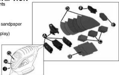
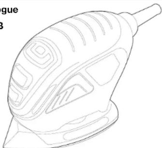
FUNCTIONAL DESCRIPTION
A. Contour sanding attachments
B. Contour sandpaper
C. Sandpaper tips
D. Sandpaper
E. Finger, sanging attachment sandpaper
F. Fingersanding attachment
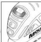
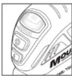
G. Zone INDICATOR ("U" display)
H. "OFF" Switch
I. "ON" Switch
SAFETY WARNINGS AND INSTRUCTIONS: SANDERS
ALWAYS WEAR PROPER EYE AND RESPIRATORY PROTECTION.
Clean your tool out periodically.
OTHER IMPORTANT SAFETY WARNINGS AND INSTRUCTIONS
Extension Cords
When using an extension cord, be sure to use one heavy enough to carry the current your product will draw. An undersized cord will cause a drop in line voltage resulting in loss of power and overheating. The following table shows the correct size to use depending on cord length and nameplate ampere rating. If in doubt, use the next heavier gauge. The smaller the gauge number, the heavier the cord.
| Minimum Gauge for Cord Sets | |||||
| Volts Total Length of Cord in Feet | |||||
| 120V 0-25 26-50 51-100 101-150 | |||||
| (0-7.6m) (7.6-15.2m) (15.2-30.4m) (30.4-45.7m) | |||||
| 240V 0-50 51-100 101-200 201-300 | |||||
| (0-15.2m) (15.2-30.4m) (30.4-60.9m) (60.9-91.4m) | |||||
| Ampere Rating | |||||
| More Than | Not more Than | American Wire Gauge | |||
| 0 | 6 | 18 | 16 | 16 | 14 |
| 6 | 10 | 18 | 16 | 14 | 12 |
| 10 | 12 | 16 | 16 | 14 | 12 |
| 12 | 16 | 14 | 12 | Not Recommended | |
SANDING
Lead Based Paint
Sanding of lead based paint is NOT RECOMMENDED due to the difficulty of controlling the contaminated dust. The greatest danger of lead poisoning is to children and pregnant women. Since it is difficult to identify whether or not a paint contains lead without a chemical analysis, we recommend the following precautions when sanding any paint:
Personal Safety
- No children or pregnant women should enter the work area where the paint sanding is being done until all clean up is completed.
- A dust mask or respirator should be worn by all persons entering the work area. The filter should be replaced daily or whenever the wearer has difficulty breathing.
NOTE: Only those dust masks suitable for working with lead paint dust and fumes be used. Ordinary painting masks do not offer this protection. See your local hardw dealer for the proper (NIOSH approved) mask. - NO EATING, DRINKING or SMOKING should be done in the work area to prevent ingesting contaminated paint particles. Workers should wash and clean up BEFORE eating, drinking or smoking. Articles of food, drink, or smoking should not be left in the work area where dust would settle on them.
Environmental Safety
- Paint should be removed in such a manner as to minimize the amount of dust generated.
-
Areas where paint removal is occurring should be sealed with plastic sheeting of 4 mils thickness.
-
Sanding should be done in a manner to reduce tracking of paint dust outside the work area.
Cleaning and Disposal
- All surfaces in the work area should be vacumured and thoroughly cleaned daily for the duration of the sanding project. Vacuum filter bags should be changed frequently.
- Plastic drop cloths should be gathered up and disposed of along with any dust chips or other removal debris. They should be placed in sealed refuse receptacles and disposed of through regular trash pick-up procedures. During clean up, children and pregnant women should be kept away from the immediate work area.
- All toys, washable furniture and utensils used by children should be washed thoroughly before being used again.
Motor
Be sure your power supply agrees with napeplate marking. 120 Volts AC only means your tool will operate on standard 60Hz household power. Do not operate AC tools on DC. A rating of 120 volts AC/DC means that you tool will operate on standard 60Hz AC or DC power. This information is printed on the napeplate. Lower voltage will cause loss of power and can result in over-heating. All Black & Decker tools are factory-tested; if this tool does not operate, check the power supply.
OPERATING INSTRUCTIONS
WARNING: To reduce the risk of serious personal injury, read, understand and follow all important safety warnings and instructions prior to using this tool.
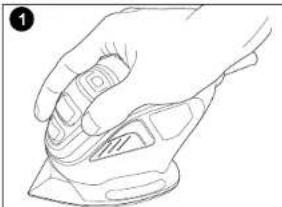
Switch
To turn the tool ON, hold it as shown in Figure 1 and push the portion of the switch marked "I". To turn the tool OFF, push the portion of the switch marked "O".
Operation
Grasp product as shown in Figure 1 and turn it on. Move it in long sweeping strokes across the surface, letting it do the work. Light pressure is all that is required. Use "Zone Touch" as described below to monitor the pressure. NOTE: Excessive pressure may result in harming or causingDIVS in the surface you are sanding. Check your work often, product is capable of removing material rapidly.
CAUTION: Shock Hazard. Under no circumstances should this product be used near water.
Zone Touch
Calibration
A calibration feature has been designed in this sander to measure the variation of voltage going into the sander from your outlet. This calibration feature automatically sets the Zone Touch feature to optimize the performance of your tool. To achieve proper calibration be sure to follow the instructions below.
-
Hold sander off work piece and turn on
-
Maintain this position while a red light appears in the center of the Zone Indicator ("U" display) and flashes 6 times.
The red light turns off and a low intensity green light will appear at the lower portion of the
Zone indicator ("U" display). Calibration is complete and you are ready to begin sanding. - Apply sander to work piece and begin sanding. Zone Touch Technology is ready to work for you.
Repeat procedure each time sander is turned on.
Note: You must repeat this process each time the sander is turned on to optimize your Zone Touch feature. Failure to follow the proper procedure may result in the "zones" not working as intended for optimal performance.
If you forget to calibrate your sander once it's turned on, simply turn the sander off and repeat the steps above.
ZONES
There are three zones which provide feedback information relating to the pressure being applied to the tool.
ZONE
Displays when
- There is no pressure being applied to the tool.
Light pressure is being applied
- Detailing with a contour attachment
- Detailing with finger attachment
Zone Lens will illuminate a low intensity green light which appears at the lower portion of the Zone Indicator ("U" display).
ZONE2
Displays when:
Optimum pressure is being applied to achieve optimum
performance and low fatigue
Zone Lens will illuminate a high intensity green light which will
appear all across the Zone Indicator ("U" display).
ZONE 3
Displays when:
Too much pressure is being applied.
Zone Lens will illuminate a red light which will appear in the center of the Zone Indicator ("U" display).
NOTE: Excessive pressure may result in harming or causing divots in the surface you are sanding.

Detail Sanding
WARNING: Always unplug product from power supply before any of the following operations.
Your tool is equipped with a teardrop base which allows you to use it on large flat surfaces and tight spots or corners.
The pad tips may wear unevenly, depending on use. The pads are designed to allow you to interchange and/or rotate the diamond tip.
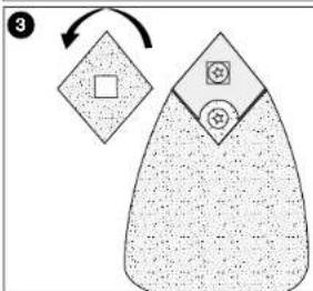
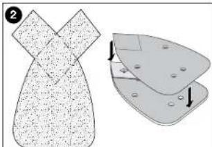
Fitting Sanding Sheets (Fig. 2)
-
Detach the two diamond-shaped tips from the sanding sheet.
-
Hold the tool with the sanding base facing upwards.
Place the sanding sheet onto the sanding
The diamond-shaped tip can be reversed and replaced when wom.
-
When the front part of the tip is worn, detach it from the sheet, reverse it and press it onto the sanding base again.
-
When the whole tip is worn, remove it from the sanding base and fit a new tip.
Tip of the Sanding Base (Fig. 3)
When the sanding base tip is worn, it can be reversed or replaced.
- Reverse or replace the worn part.
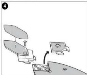
Finger Attachment (Fig. 4)
The finger attachment is used for fine detail sanding.
-
Remove the screw.
-
Remove the diamond-shaped tip holder from the sanding base.
-
Fit the finger attachment onto the sanding base
-
Fit and tighten the screw.
Align the sanding sheet with the finger attachment.
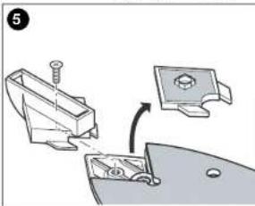
Contour Holder Attachment (Fig. 5)
The contour sanding pieces are for sanding curved surfaces and grooves.
-
Remove the screw.
-
Remove the diamond-shaped tip holder from the sanding base.
-
Fit the contour holder onto the sanding base.
-
Fit and tighten the screw.
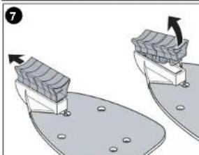
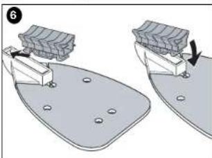
Fitting and Removing a Contour Piece (Fig. 6 & 7)
- Choose the contour sanding piece profile most suitable for your application.
- Place one end of the contour sanding piece into the recess at the front end of the contour
holder - Push the other end of the contour sanding piece until it clicks into place.
- To remove the contour sanding piece, push it forward then pull the rear end out of the contour holder (fig. 7).
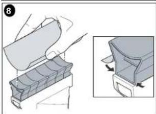
Fitting a Sanding Sheet Onto a Contour Sanding Piece (Fig. 8)
- Align the sanding sheet with the contour sanding piece.
- Press the sanding sheet onto the contour sanding piece, making sure that the sanding sheet follows the shape of the profile.
Maintenance
Use only mild soap and damp cloth to clean the tool. Never let any liquid get inside the tool; never immerse any part of the tool into a liquid.
IMPORTANT: To assure product SAFETY and RELIABILITY, repairs, maintenance and adjustment should be performed by authorized service centers or other qualified service organizations, always using identical replacement parts.
Accessories
Look for the following MouseTM accessories at your local retailer.
Catalog # Description Contents
| 74-583 120 Medium Sandpaper 5 sheets |
| 74-584 180 Fine Sandpaper 5 sheets |
| 74-595 220 Extra Fine Sandpaper 5 sheets |
| 74-586 Sandpaper Assortment 1 sheet of 120 grit paper, 2 sheets each 180, 220 paper |
| 74-587 Finger Attachment Paper 5 fingers each of 120, 180, 220 | |
| 74-588 1 OT Power Wool | 3 sheets |
| 74-589 4 OT Power Wool | 3 sheets |
| 74-583 4 OT Power Wool | 3 sheets |
| 74-581 Polishing Kit | 2 sheets of 1 OT power wool, 2 sheets of 4 OT power wool, 2 foam pads |
| 74-582 Scrubbing Kit | 2 coarse abrasive pads, 2 fine abrasive pads, 2 foam pads |
| 74-580 Sanding/Polishing Kit | 2 sheets of 1 OT power wool, 2 sheets of 180 grit sandpaper, 2 sheets of 240 grit sandpaper, 2 foam pads, 5 finger attachment paper |
| 74-671 Universal Sandpaper/Coarse 5 sheets of 80 grit |
| 74-672 Universal Sandpaper/Med. 5 sheets of 120 grit |
| 74-673 Universal Sandpaper/Fine 5 sheets of 220 grit |
| 74-674 Universal Sandpaper | Assortment |
| 200 | 100 |
Recommended accessories for use with your tool are available at extra cost. Listings per retailer may vary. The hook and loop pad and individual bases are replaceable parts. If they become worn, contact your local service center. For more information call:
-800-544-6986.
WARNING: The use of any accessory not recommended for use with this tool could be
hazardous
Application / Accessory Matrix
ACCESSORY
MEDIUM GRIT SANDPAPER
FINE GRIT SANDEAPER
EXTRA FINE GRIT SANDPAPER
DETAIL SANDING TIPS
1OT POLISHING/STRIPPING WOOL
4OTFINEPOLISHINGWOOL
GREY FOM PAD
WHITE NON-WOVEN FAB
WHILE NON-WOVEN PAX 1
HEDNONWOVENTAD
RECOMMENDED APPLICATIONS/USES
PAINT, VARNISH, RUST REMOVAL
SUBFACE BLENDING AND FINISHING
SANDING BETWEEN COATS OF PAINT OR YARNISH
CORNERS / HARD TO REACH PLACES
POLISHING METALS/STRIPPING VARNISH OR URETHANE
FINE POLISHING, SATIN FINISH ON PAINT / VARNISH / URETHANE
APPLYING AND REMOVIDING POLISH
LIGHT CRUIRING
HEAVY SCRUBBING / BLAST REPOVAX
The pads described above are available in kits where Mouse products are sold. The hook and loop pad and individual bases are replaceable parts. If they become worn, contact with the pad or the base of the pad will cause it to break down.
your local service center. For more information call 1-800-544-6986.
TROUBLESHOOTING
Problem Possible Cause Possible Solution
- Zone lights do not work - Voltage to tool is - Plug tool in outlet that is
as intended below 120 volts. not shared.
-
Re-calibrate tool (refer to calibration section in manual).
-
Use product as intended, lights will not cause the tool to operate differently.
-
Red indicator will continue to warn against too much pressure.
-
Unit will not start. - Cord not plugged in. - Plug tool into a working outlet.
Circuit fuse is blown. Replace circuit fuse. (If the product
repeatedly causes the circuit fuse to blow, discontinue use immediately and have it serviced at a Black & Docker sensor or by authorized servicer.
- Circuit breaker is - Reset circuit breaker.
tripped. (If the product repeatedly causes the circuit breaker to trip, discontinue use immediately and have it serviced at a
Black & Decker service center or
authorized servicer.)
Cord or switch is
- Have cord or switch replaced.
at Black & Decker Service Center or Authorized Servicer.
For assistance with your product, visit our website www.blackanddecker.com for the location of the service center nearest you or call the BLACK & DECKER help line at 1-800-234-5697.
Service Information
Black & Decker offers a full network of company-owned and authorized service locations throughout North America. All Black & Decker Service Centers are staffed with trained personnel to provide customers with efficient and reliable power tool service. Whether you need technical advice, repair, or genuine factory replacement parts, contact the Black & Decker location nearest you. To find your local service location, refer to the yellow page directory under "Tools—Electric" or call: 1-800-544-6986.
Full Two-Year Home Use Warranty
Black & Decker (U.S.) Inc. warrants this product for two years against any defects in material or workmanship. The defective product will be replaced or repaired at no charge in either of two ways.
The first, which will result in exchanges only, is to return the product to the retailer from whom it was purchased (provided that the store is a participating retailer). Returns should be made within the time period of the retailer's policy for exchanges (usually 30 to 90 days after the sale). Proof of purchase may be required. Please check with the retailer for their specific return policy regarding returns that are beyond the time set for exchanges. The second option is to take or send the product (prepaid) to a Black & Decker owned or authorized Service Center for repair or replacement at our option. Proof of purchase may be required. Black & Decker owned and authorized Service Centers are listed under "Tools-Electric" in the yellow pages of the phone directory and on our website www.blackanddecker.com.
This warranty does not apply to accessories. This warranty gives you specific legal rights and you may have other rights which vary from state to state. Should you have any questions, contact the manager of your nearest Black & Decker Service Center. This product is not intended for commercial use.
Free warning label replacement: If your warning labels become illegible or are missing, call 1-800-544-6986 for a free replacement.
LATIN AMERICA: This warranty does not apply to products sold in Latin America. For products sold in Latin America, check country specific warranty information contained in the packaging, call the local company or see the website for warranty information.
Imported by
Black & Decker (U.S.) Inc. 701 E. Joppa Rd., Rockville, MD 20836
Towson, MD 21286 U.S.A.

See 'Tools-Electric' -Yellow Pages-for Service & Sales
BLACK&DECKER
MINIPONCEUSE AVEC SYSTÉME DE ZONE
MODE D'EMPLOI
N^o de catalogue
MS600B
Black & Decker Canada Inc.
100 Central Ave.
APPLICARY REMOVER PULIMENTO
TALLADOLIGERO
TALLADO PESADO / REMOCION DE OXIDO
Col. Eldo Jr. de Mavc Boca Del Rio, Veracruz
Tel. 01 229 167 89 89
Servicio de Fabrica Black & Decker, S.A. de C.V.
Black & Becker, S.A., 16-20. Lazardo Cardenas No. 18
Corr. Correa
Distrito Federal
Mexico
Tel.55889502
Col. Felipe Camillo Puerto
Cd.Madero,Tampico Tel.018322124 50
Perifles y Herramrientas de Morlla
Moraal Gertrudis Bocanegra No.898
Col. Ventura Puente Morlla, Michoapan
Tel.014433138550
Enrique Robles
Department of Mathematics, University of Washington
Form No. 90518305 REV. 3 Printed in China
Copyright © 2009 Black & Decker DEC. 09