
Matrix BDCMTR - Multitools BLACK & DECKER - Free user manual and instructions
Find the device manual for free Matrix BDCMTR BLACK & DECKER in PDF.
| Product type | Router module for Matrix system |
| Brand | Black & Decker |
| Model | Matrix BDCMTR |
| Power supply | Via Matrix power unit (not included) |
| Variable speed | Yes, by trigger |
| Adjustable cutting depth | Yes, by rotating the base |
| Max bit diameter | 35 mm (1-3/8 in) |
| Collet type | 6.4 mm (1/4 in) collet |
| Spindle lock | Yes, for bit change |
| Suitable materials | Wood, panels, plastics |
| Use | Grooving, profiling, flush trimming |
| Direction of travel | Counterclockwise for outer edges, clockwise for inner edges |
| Eye protection required | Yes, ANSI Z87.1 compliant |
| Hearing protection required | Yes, depending on duration of use |
| Respiratory protection recommended | Yes, in case of dust |
| Maintenance | Clean with mild soap and a damp cloth |
| Warranty | 2 years for domestic use |
| Compatible accessories | HSS and carbide bits, cutting guide |
| Weight | Approx 0.5 kg (estimated) |
| Dimensions (L x W x H) | Approx 200 x 80 x 170 mm (estimated) |
Frequently Asked Questions - Matrix BDCMTR BLACK & DECKER
User questions about Matrix BDCMTR BLACK & DECKER
0 question about this device. Answer the ones you know or ask your own.
Ask a new question about this device
Download the instructions for your Multitools in PDF format for free! Find your manual Matrix BDCMTR - BLACK & DECKER and take your electronic device back in hand. On this page are published all the documents necessary for the use of your device. Matrix BDCMTR by BLACK & DECKER.
USER MANUAL Matrix BDCMTR BLACK & DECKER
If you have a question or experience a problem with your BLACK+DECKER purchase, go to http://www.blackanddecker.com/instantanswers
If you can't find the answer or do not have access to the Internet, call 1-800-544-6986 from 8 a.m. to 5 p.m. EST Mon. - Fri. to speak with an agent.
Please have the catalog number available when you call. SAVE THIS MANUAL FOR FUTURE REFERENCE
VEA EL ESPANOL EN LA CONTRAPORTADA. INSTRUCTIVO DE OPERATION, CENTROS DE SERVICIO Y POLIZA DE GARANTIA. ADVERTENCIA: LEASE Este INSTRUCTIVO ANTES DE USAR EL PRODUCTO.
SYMBOL SIGNAL MEANING
SAFETY ALERT SYMBOL: Indicates DANGER, WARNING, OR CAUTION. May be used in conjunction with other symbols or pictographs.
DANGER: Indicates hazardous situation which, if not avoided, will result in death or serious injury.
WARNING: Indicates hazardous situation which, if not avoided, could result in death or serious injury.
CAUTION: Indicates a hazardous situation which, if not avoided, could result in minor or mod er ate injury or property damage.
WARNING: Read all safety warnings and all instructions. Failure to follow the warnings and instructions may result in electric shock, fire and/or serious injury. Save all warnings and instructions for future reference.
WARNING: Read all safety warnings and all instructions provided with your Power Unit (BDCDMT112, BDCDMT120, or BDEDMT) before using this attachment. Failure to follow the warnings and instructions may result in electric shock, fire and/or serious injury.
SPECIFIC SAFETY RULES
- Hold power tool by insulated gripping surfaces, because the cutter may contact its own cord. Cutting a "live" wire may make exposed metal parts of the power tool "live" and shock the operator.
- Use clamps or another practical way to secure and support the workpiece to a stable platform. Holding the work by your hand or against the body leaves it unstable and may lead to loss of control.
- Keep handles dry, clean, and free from oil and grease. This will enable better control of the tool.
- Keep hands away from cutting area. Never reach under the workpiece for any reason.
- Keep the router base firmly in contact with the workpiece when cutting. Hold the router only by identified gripping surfaces as identified in this manual (see Using the Router).
These precautions will reduce the risk of personal injury.
Kickback is a sudden reaction to a pinched, bound or misaligned router bit, causing an uncontrolled router to lift up and out of the workpiece toward the operator.
- Keep your body positioned parallel to the direction of the cut, not behind the direction of the cut. KICKBACK could cause the router to jump opposite the direction of the cut.
- Use sharp cutters. Dull cutters may cause the router to swerve or stall under pressure.
- Never touch the bit immediately after use. It may be extremely hot.
- Be sure that the motor has stopped completely before you lay the router down. If the cutter head is still spinning when the tool is laid down, it could cause injury or damage.
- Be sure that the router bit is clear of the workpiece before starting the motor. If the bit is in contact with the workpiece when the motor starts it could make the router jump, causing damage or injury.
Only use router bits with a shank diameter of 1/4".
Only use router bits rated at least equal to the maximum speed marked on the tool. - Do not use router bits with a diameter greater than 1-3/8" (35mm). Use of larger than recommended bits can result in a hazard.
- Not intended to be used with a router table. Do not use the tool in an inverted position.
- Do not attempt to use the tool in a stationary mode.
- Make sure collet nut is securely tightened to prevent router bit from slipping during use.
WARNING: ALWAYS use safety glasses. Everyday eyeglasses are NOT safety glasses. Also use face or dust mask if drilling operation is dusty. ALWAYS WEAR CERTIFIED SAFETY EQUIPMENT:
ANSI Z87.1 eye protection (CAN/CPA Z94.3),
ANSI S12.6 (S3.19) hearing protection,
NOSH/OSHA respiratory protection.
WARNING: Some dust created by power sanding, sawing, grinding, drilling, and other construction activities contains chemicals known to the state of California to cause cancer, birth defects or other reproductive harm. Some examples of these chemicals are:
- lead from lead-based paints,
crystalline silica from bricks and cement and other masonry products, and
arsenic and chromium from chemically-treated lumber.
Your risk from these exposures varies, depending on how often you do this type of work. To reduce your exposure to these chemicals: work in a well ventilated area, and work with approved safety equipment, such as those dust masks that are specially designed to filter out microscopic particles.
- Avoid prolonged contact with dust from power sanding, sawing, grinding, drilling, and other construction activities. Wear protective clothing and wash exposed areas with soap and water. Allowing dust to get into your mouth, eyes, or lay on the skin may promote absorption of harmful chemicals.
WARNING: Use of this tool can generate and/or disperse dust, which may cause serious and permanent respiratory or other injury. Always use NOSH/OSHA approved respiratory protection appropriate for the dust exposure. Direct particles away from face and body. Always operate tool in well-ventilated area and provide for proper dust removal. Use dust collection system wherever possible.
WARNING: ALWAYS wear proper personal hearing protection that conforms to ANSI S12.6 (S3.19) during use. Under some conditions and duration of use, noise from this product may contribute to hearing loss.
SYMBOLS
The label on your tool may include the following symbols. The symbols and their definitions are as follows:
| V.........volts | A..........amperes |
| Hz..........hertz | W..........watts |
| min..........minutes | ~or AC......alternating current |
| =or DC..direct current | n0..........no load speed |
| Class I Construction | ±..........earthing terminal |
| (grounded)..........safety alert symbol | |
| Class II Construction .../min or rpm....revolutions or reciprocation | |
| (double insulated) | per minute |
| Read instruction manual before use | Use proper respiratory protection |
| Use proper eye protection | Use proper hearing protection |
When using an extension cord, be sure to use one heavy enough to carry the current your product will draw. An undersized cord will cause a drop in line voltage resulting in loss of power and overheating. The following table shows the correct size to use depending on cord length and nameplate ampere rating. If in doubt, use the next heavier gage. The smaller the gage number, the heavier the cord.
| Minimum Gauge for Cord Sets | |||||
| Volts | Total Length of Cord in Feet | ||||
| 120V | 0-25 | 26-50 | 51-100 | 101-150 | |
| (0-7,6m) | (7,6-15,2m) | (15,2-30,4m) | (30,4-45,7m) | ||
| 240V | 0-50 | 51-100 | 101-200 | 201-300 | |
| (0-15,2m) | (15,2-30,4m) | (30,4-60,9m) | (60,9-91,4m) | ||
| Ampere Rating | |||||
| More | Not more | American Wire Gauge | |||
| Than | Than | ||||
| 0 - | 6 | 18 | 16 | 16 | 14 |
| 6 - | 10 | 18 | 16 | 14 | 12 |
| 10 - | 12 | 16 | 16 | 14 | 12 |
| 12 - | 16 | 14 | 12 | Not Recommended | |
SAVE THESE INSTRUCTIONS
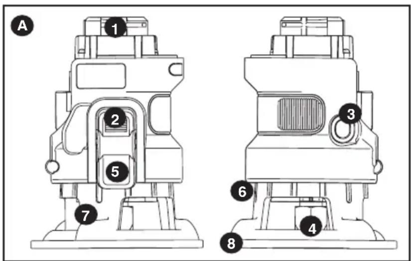
Functional Description
Figure A
- Router attachment
- Spindle lock button
- Active lock-off button
- Nut and Collet
- Depth stop bar
- Depth of cut scale
- Chip shield
- Base
Not shown:
Wrench
OPERATING INSTRUCTIONS
WARNING: Shock hazard. Under no circumstances should this product be used near water.
WARNING: To reduce the risk of injury, turn off and remove battery from tool or disconnect plug from power source before making any adjustments or removing or installing attachments or accessories.
WARNING: Risk of lacerations or burns. Do not touch work piece or bit immediately after operating the tool. They can become very hot. Handle carefully. Always allow accessories and workpiece to cool before handling.
NOTE: Refer to Power Unit instruction manual before operating this tool for all safety warnings and details on installing and removing attachments.
OPERATION
- To switch the tool on, press and hold the active lock-off button (3), then fully press the variable speed switch on the power unit. Once the bit begins to operate, release the active lock-off button (3).
- To switch the tool off, release the variable speed switch.
NOTE: Operate the router at full speed at all times.
NOTE: This attachment only operates in the forward direction, the forward/reverse slider of the Power Unit should not be able to be switch to reverse.
INSTALLING AND REMOVING A ROUTER BIT
WARNING: To reduce the risk of injury, turn off and remove battery from tool or disconnect plug from power source before making any adjustments or removing or installing attachments or changing bits. Failure to do so could result in accidental starting and possible injury.
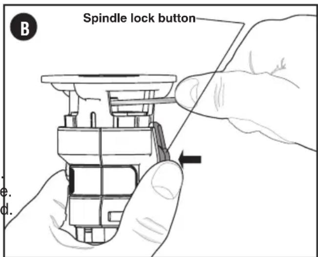
BIT INSTALLATION AND REMOVAL (FIG. B)
NOTES:
- ROUTER IS NOT RECOMMENDED FOR USE WITH RAISED PANEL BITS.
- ROUTER IS NOT RECOMMENDED FOR USE IN METAL CUTTING APPLICATIONS.
DO NOT USE ANY ROUTER BIT GREATER THAN 1-3/8" DIAMETER. USE PILOT (BALL BEARING) ROUTER BITS FOR EDGE PROFILE CUTTING.
CAUTION: ROUTER BITS ARE SHARP, USE CARE WHEN HANDLING THEM.
INSTALLING BITS
WARNING: Turn the router off and remove battery from tool or disconnect plug from power source.
The router is equipped with a spindle lock feature that makes changing bits easy. Lock the spindle shaft by depressing the spindle lock button as shown in figure B and use the supplied wrench to loosen (counterclockwise) the collet nut (4).
- Keep the spindle lock button (2) depressed and rotate the spindle until the spindle lock fully engages.
- Place the router upside down on a smooth, flat surface.
- Loosen the collet nut (4) using the wrench provided. Insert the shank of the router bit into the collet (4).
- When installing router bits, be sure they are inserted as far as possible and then pulled out about 1/16 (1.5mm).
- Keep the spindle lock button (2) depressed and tighten the collet nut (4) clockwise (do not overtighten) using the wrench provided.
NOTE: If the router base is set at its maximum depth, the collet nut cannot be tightened properly. Always insure that if the router base is adjusted to its maximum depth it must be backed off several rotations (counterclockwise) before tightening or loosening router bits. See "Setting the Router Depth" below for router base adjustment.
CAUTION: NEVER TIGHTEN COLLET NUT WITHOUT A 1/4” SHANK SIZE BIT INSERTED INTO COLLET. TO DO SO MAY BREAK OR DAMAGE COLLET.
REMOVING BITS
CAUTION: Burn hazard. Router bits get hot during use. Allow sufficient time for bit to cool before replacing.
- Keep the spindle lock button (2) depressed.
- Place the router upside down on a smooth, flat surface.
- Loosen (counterclockwise) the collet nut (4) using the wrench provided.
- Release button and remove bit.
CONTROLS
WARNING: To reduce the risk of injury, do not overload the tool. Let it work at its own pace.
WARNING: To reduce the risk of injury, turn off and remove battery from tool or disconnect plug from power source before making any adjustments or removing or installing attachments or accessories.
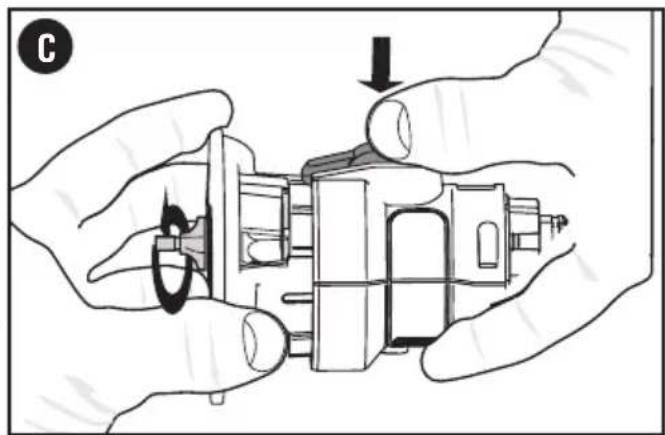
SETTING THE ROUTING DEPTH (FIG.C)
WARNING: Turn the router off and remove battery from tool or disconnect plug from power source.
- Keep the spindle lock button (2) depressed and rotate the router base (8) as shown in figure C. Rotating the base clockwise will increase the routing depth while rotating the basecounterclockwise will decrease the depth. Two complete revolutions of the base equals about 2 millimeters.
- After obtaining the desired routing depth, release the spindle lock button (2). Continue turning the base until the notch under the spindle lock button aligns with the next closest locking slot in the depth of cut scale (6).
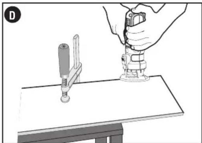
USING THE ROUTER (FIG. D & E)
- Make sure that the material to be cut is clamped down and is stable enough to support the router during operation.
- Use both hands on the power unit to control the router, and run the router at full speed at all times. See figure D.
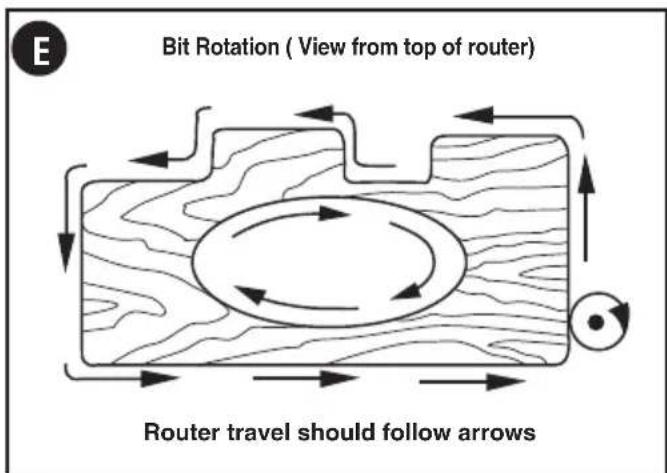
- Move the router counterclockwise when cutting outside edges. Move clockwise when cutting inside edges. See figure E.
FEEDING SPEED AND RATE OF CUT
Variation between materials and bit configurations dictates a wide variety of feed rates.
Experience is the best measure for determining feed rate. Become familiar with the sound and feel of the router by making practice cuts in scrap material.
The router bit rotates at a very high speed and may heat up if the router is moved too slowly through the wood and cause burn marks. Feeding the router too fast or trying to remove too much material in a single pass will overload the motor. Use two or more passes for extra-large cuts (over 1/8" deep), especially in hard woods.
HINTS FOR OPTIMUM USE
When working on outside edges, move the tool counterclockwise (figure E). When working on inside edges, move the tool clockwise.
- Use pilot (ball bearing) router bits for edge profile cutting.
Use HSS (high speed steel) router bits for softwood. - Use TCT (tungsten carbide tipped) router bits for hardwood.
Not recommended for plunge cutting.
TROUBLESHOOTING
Problem
- Unit will not start.
Possible Cause
- Attachment is not secured. pushed into the Power Unit.
Possible Solution
- Make certain the attachment is fully
For assistance with your product, visit our website www.blackanddecker.com for the location of the service center nearest you or call the BLACK+DECKER help line at 1-800-544-6986.
NOTE: Refer to Power Unit instruction manual for troubleshooting solutions regarding operation of the Power Unit.
MAINTENANCE
Use only mild soap and damp cloth to clean the tool. Never let any liquid get inside the tool; never immerse any part of the tool into a liquid.
IMPORTANT: To assure product SAFETY and RELIABILITY, repairs, maintenance and adjustment (other than those listed in this manual) should be performed by authorized service centers or other qualified service personnel, always using identical replacement parts.
ACCESSIONS
WARNING: The use of any accessory not recommended for use with this tool could be hazardous. Recommended accessories for use with your tool are available from your local dealer or authorized service center. If you need assistance regarding accessories, please call: 1-800-544-6986.
This device complies with part 15 of the FCC rules. Operation is subject to the following two conditions: (1) This device may not cause harmful interference, and (2) this device must accept any interference received, including interference that may cause undesired operation.
NOTE: This equipment has been tested and found to comply with the limits for a Class B digital device, pursuant to Part 15 of the FCC Rules. These limits are designed to provide reasonable protection against harmful interference in a residential installation. This equipment generates, uses and can radiate radio frequency energy and, if not installed and used in accordance with the instructions, may cause harmful interference to radio communications. However, there is no guarantee that interference will not occur in a particular installation.
If this equipment does cause harmful interference to radio or television reception, which can be determined by turning the equipment off and on, the user is encouraged to try to correct the interference by one or more of the following measures:
- Reorient or relocate the receiving antenna.
- Increase the separation between the equipment and receiver.
- Connect the equipment into an outlet on a circuit different from that to which the receiver is connected.
- Consult the dealer or an experienced radio/TV technician for help.
Changes or modifications to this unit not expressly approved by the party responsible for compliance could void the user's authority to operate the equipment. This Class B digital apparatus complies with Canadian ICES-003.
SERVICE INFORMATION
All BLACK+DECKER Service Centers are staffed with trained personnel to provide customers with efficient and reliable power tool service. Whether you need technical advice, repair, or genuine factory replacement parts, contact the BLACK+DECKER location nearest you. To find your local service location, call: 1-800-544-6986 or visit www.blackanddecker.com
FULL TWO-YEAR HOME USE WARRANTY
Black & Decker (U.S.) Inc. warrants this product for two years against any defects in material or workmanship. The defective product will be replaced or repaired at no charge in either of two ways. The first, which will result in exchanges only, is to return the product to the retailer from whom it was purchased (provided that the store is a participating retailer). Returns should be made within the time period of the retailer's policy for exchanges (usually 30 to 90 days after the sale). Proof of purchase may be required. Please check with the retailer for their specific return policy regarding returns that are beyond the time set for exchanges.
The second option is to take or send the product (prepaid) to a BLACK+DECKER owned or authorized Service Center for repair or replacement at our option. Proof of purchase may be required.
This warranty does not apply to accessories. This warranty gives you specific legal rights and you may have other rights which vary from state to state or province to province. Should you have any questions, contact the manager of your nearest BLACK+DECKER Service Center.
This product is not intended for commercial use.
FREE WARNING LABEL REPLACEMENT: If your warning labels become illegible or are missing, call 1-800-544-6986 for a free replacement.
LATIN AMERICA: This warranty does not apply to products sold in Latin America. For products sold in Latin America, check country specific warranty information contained in the packaging, call the local company or see the website for warranty information.
Imported by: Black & Decker (U.S.) Inc., 701 E. Joppa Rd. Towson, MD 21286 U.S.A.

BLACK+ DECKER
MATRIX
MODULE DETOUPIE
MODE D'EMPLOI
NUMERO DE CATALOGUE BDCMTR
Col. Americana, S. Juarez
Guadalajara, Jalisco
Tel. 01 33 38 25 69 78
Col. Fracc. Universidad
Chihuahua, Chihuahua
Tel. 01 614 413 64 04
Fernando González Armenta
Bolivia No. 605
Col. Felipe Carrillo Puerto
Cd. Madero, Tamaulipas
Tel. 01 833 221 34 50


- SYMBOL SIGNAL MEANING
- SPECIFIC SAFETY RULES
- SYMBOLS
- SAVE THESE INSTRUCTIONS
- Functional Description
- Figure A
- OPERATING INSTRUCTIONS
- OPERATION
- INSTALLING AND REMOVING A ROUTER BIT
- BIT INSTALLATION AND REMOVAL (FIG. B)
- NOTES:
- INSTALLING BITS
- CAUTION: NEVER TIGHTEN COLLET NUT WITHOUT A 1/4” SHANK SIZE BIT INSERTED INTO COLLET. TO DO SO MAY BREAK OR DAMAGE COLLET.
- REMOVING BITS
- CONTROLS
- SETTING THE ROUTING DEPTH (FIG.C)
- USING THE ROUTER (FIG. D & E)
- FEEDING SPEED AND RATE OF CUT
- HINTS FOR OPTIMUM USE
- TROUBLESHOOTING
- Problem
- Possible Cause
- Possible Solution
- MAINTENANCE
- ACCESSIONS
- SERVICE INFORMATION
- FULL TWO-YEAR HOME USE WARRANTY
- BLACK+ DECKER
- MATRIX
- MODULE DETOUPIE
- NUMERO DE CATALOGUE BDCMTR
Brand : BLACK & DECKER
Model : Matrix BDCMTR
Category : Multitools