DW156 - Drill DEWALT - Free user manual and instructions
Find the device manual for free DW156 DEWALT in PDF.


| Product Type | Magnetic Drill Press |
| Brand | DeWALT |
| Model | DW156 |
| Power Supply | 120 V AC, 60 Hz, 10 A |
| No-Load Speed | 375 RPM |
| Rated Magnetic Force | 700 lb (318 kg) |
| Drilling Capacity (twist drills) | 6 mm to 21 mm (1/4" to 13/16") |
| Minimum Steel Thickness for Magnet | 13 mm (1/2 in) |
| Maximum Air Gap for Optimal Magnetic Force | 0.4 mm (1/64 in) |
| Estimated Weight | 18 kg |
| Estimated Dimensions (L x W x H) | 400 x 200 x 350 mm |
| Grounding | Yes, three-wire cord with 3-prong plug |
| Safety | Two-action switch, safety chain, safety torque rod |
| Maintenance | Regularly check carbon brushes, lubricate bearings with SAE 20 or 30 oil |
| Compatible Accessories | DW1559 arbor, annular cutters, twist drills, taps, reamers |
| Warranty | 1 year against defects in material and workmanship |
| Intended Use | Drilling and tapping on steel, with magnet for vertical or overhead attachment |
| Magnet Activation Indicator | Yes (MAG-ON) |
| Chuck Type | Keyed chuck or arbor for annular cutters (depending on accessory) |
| Recommended Extension Cord | Three-wire with ground, gauge suitable for length and current |
Frequently Asked Questions - DW156 DEWALT
User questions about DW156 DEWALT
0 question about this device. Answer the ones you know or ask your own.
Ask a new question about this device
Download the instructions for your Drill in PDF format for free! Find your manual DW156 - DEWALT and take your electronic device back in hand. On this page are published all the documents necessary for the use of your device. DW156 by DEWALT.
USER MANUAL DW156 DEWALT
384946/DW154 9/25/00 1:27 PM Page 2
DLWALT Industrial Tool Co., 701 East Joppa Road, Baltimore, MD 21286
DW154, DW156, DW157 Copyright © 2000
Printed in U.S.A. (SEP00-CD-1) Form No. 384946
384946/DW154
9/25/00 1:27 PM Page 3
INSTRUCTION MANUAL GUIDE D'UTILISATION MANUAL DE INSTRUCCIONES
INSTRUCTIVO DE OPERACION, CENTROS DE SERVICIO Y POLIZA DE GARANTIA. ADVERTENCIA: LÉASE ESTE INSTRUCTIVO ANTES DE USAR EL PRODUCTO.

DW154, DW156, DW157 Magnetic Drill Presses Perceuses à colonne magnétiques Taladros de columna magnéticos
384946/DW154 9/25/00 1:27 PM Page 4
IF YOU HAVE ANY QUESTIONS OR COMMENTS ABOUT THIS OR ANY DE WALT TOOL, CALL US TOLL FREE AT:
1-800-4-DEWALT (1-800-433-9258)
1
DW154 2" (50MM)
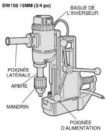
DW1563/4" (19MM)
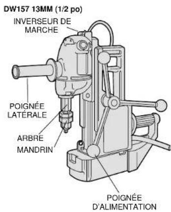
DW157 1/2" (13MM)
Important Safety Instructions
WARNING: When using electric tools, basic safety precautions should always be followed to reduce risk of fire, electric shock, and personal injury, including the following:
READ ALL INSTRUCTIONS
Grounding Instructions
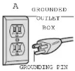
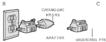
This tool should be grounded while in use to protect the operator from electric shock. The tool is equipped with a 3-conductor cord and 3-prong grounding type plug to fit the proper grounding type receptacle. The green (or green and yellow) conductor in the cord is the grounding wire. Never connect the green (or green and yellow) wire to a live terminal. If your unit is intended for use on less than 150 V, it has a plug that looks like that shown in sketch A. If it is for use on 150 to 250 V, it has a plug that looks like that shown in sketch D. An adapter, sketches B and C, is available for connecting sketch A type plugs to 2-prong receptacles. The green-colored rigid ear, lug, or the like, extending from the adapter must be connected to a permanent ground, such as a properly grounded outlet box. No adapter is available for a plug as shown in sketch D. ADAPTER SHOWN IN FIGURES B and C IS NOT FOR USE IN CANADA. Use only 3-wire extension cords that have 3-prong grounding-type plugs and 3-pole receptacles that accept the tool's plug. Replace or repair damaged cords.
Safety Instructions For All Tools
- KEEP WORK AREA CLEAN. Cluttered areas and benches invite injuries.
- CONSIDER WORK AREA ENVIRONMENT. Don't expose power tools to rain. Don't use power tools in damp or wet locations. Keep work area well lit. Do not use tool in presence of flammable liquids or gases.
- GUARD AGAINST ELECTRIC SHOCK. Prevent body contact with grounded surfaces. For example; pipes, radiators, ranges, and refrigerator enclosures.
- KEEP CHILDREN AWAY. Do not let visitors contact tool or extension cord. All visitors should be kept away from work area.
- STORE IDLE TOOLS. When not in use, tools should be stored in dry, and high or locked-up place — out of reach of children.
- DON'T FORCE TOOL. It will do the job better and safer at the rate for which it was intended.
- USE RIGHT TOOL. Don't force small tool or attachment to do the job of a heavy-duty tool. Don't use tool for purpose not intended.
- DRESS PROPERLY. Do not wear loose clothing or jewelry. They can be caught in moving parts. Rubber gloves and non-skid footwear are recommended when working outdoors. Wear protective hair covering to contain long hair.
- USE SAFETY GLASSES. Also use face or dust mask if cutting operation is dusty.
- DON'T ABUSE CORD. Never carry tool by cord or yank it to disconnect from receptacle. Keep cord from heat, oil, and sharp edges.
- SECURE WORK. Use clamps or a vise to hold work. It's safer than using your hand and it frees both hands to operate tool.
DON'T OVERREACH. Keep proper footing and balance at all times. - MAINTAIN TOOLS WITH CARE. Keep tools sharp and clean for better and safer performance. Follow instructions for lubricating and changing accessories. Inspect tool cords periodically and if damaged, have repaired by authorized service facility. Inspect
extension cords periodically and replace if damaged. Keep handles dry, clean, and free from oil and grease.
- DISCONNECT OR LOCK OFF TOOLS when not in use, before servicing, and when changing accessories, such as blades, bits, cutters.
- REMOVE ADJUSTING KEYS AND WRENCHES. Form habit of checking to see that keys and adjusting wrenches are removed from tool before turning it on.
- AVOID UNINTENTIONAL STARTING. Don't carry tool with finger on switch. Be sure switch is off when plugging in.
- EXTENSION CORDS. Use only 3-wire extension cords that have 3-prong grounding-type plugs and 3-pole receptacles that accept the tool's plug. Replace or repair damaged cords. Make sure your extension cord is in good condition. When using an extension cord, be sure to use one heavy enough to carry the current your product will draw. An undersized cord will cause a drop in line voltage resulting in loss of power and overheating. The following table shows the correct size to use depending on cord length and nameplate ampere rating. If in doubt, use the next heavier gage. The smaller the gage number, the heavier the cord.
- OUTDOOR USE EXTENSION CORDS. When tool is used outdoors, use only extension cords intended for use outdoors and so marked.
Minimum Gage for Cord Sets
| Volts Total Length of Cord in Feet | ||||||
| 120V 0-25 26-50 51-100 101-150 | ||||||
| 240V 0-50 51-100 101-200 201-300 | ||||||
| Ampere Rating | ||||||
| More Not more American Wire Gage (AWG) | ||||||
| Than Than | ||||||
| 0 | - | 6 | 1 | 8 | 1 | 6 |
| 6 | - | 10 | 18 | 16 | 14 | 12 |
| 10 | - | 12 | 16 | 16 | 14 | 12 |
| 12 | - | 16 | 14 | 12 | Not Recommended | |
STAY ALERT. Watch what you are doing. Use common sense. Do not operate tool when you are tired.
- CHECK DAMAGED PARTS. Before further use of the tool, a guard or other part that is damaged should be carefully checked to determine that it will operate properly and perform its intended function. Check for alignment of moving parts, binding of moving parts, breakage of parts, mounting, and any other conditions that may affect its operation. A guard or other part that is damaged should be properly repaired or replaced by an authorized service center unless otherwise indicated elsewhere in this instruction manual. Have defective switches replaced by authorized service center. Do not use tool if switch does not turn it on and off.
CAUTION: When drilling into walls, floors or wherever "live" electrical wires may be encountered, DO NOT TOUCH ANY METAL PARTS OF THE TOOL! Hold the tool only by the insulated grasping surfaces to prevent electric shock if you drill or drive into a live wire.
Additional Safety Instructions
- Always be sure that the drill press is plugged into the correct voltage system. Place cord so that it cannot be pulled from the receptacle accidentally. Check for correct line fuse.
Before operating unit, make sure it is grounded correctly in accordance with instructions under "Grounding." - Always use safety chain when working on vertical or overhead beams since electrical supply may fail or unit may accidentally be disconnected. Connect safety chain immediately after magnet unit is set in place.
- Always use the correct gage extension wire (see Extension Wire Table).
- Use a back-up plate when magnet is mounted on thin material, the total thickness should be 1/2^ (13mm) or more. See instructions under "Operation."
- Care should be taken to place the base on a flat surface. Do not set magnet on objects such as bolt heads, screws, rivets, or steel
chips, since space between magnet and working surface weakens the magnetic pull.
CAUTION:DO NOT USE FEED HANDLE TO LIFT UNIT.
CAUTION: After switching to Demag, the magnetic base may continue to adhere to the work piece due to residual magnetism. A light blow with the hand will release the base.
WARNING: Some dust created by power sanding, sawing, grinding, drilling, and other construction activities contains chemicals known to cause cancer, birth defects or other reproductive harm. Some examples of these chemicals are:
- lead from lead-based paints,
crystalline silica from bricks and cement and other masonry products, and - arsenic and chromium from chemically-treated lumber (CCA).
Your risk from these exposures varies, depending on how often you do this type of work. To reduce your exposure to these chemicals: work in a well ventilated area, and work with approved safety equipment, such as those dust masks that are specially designed to filter out microscopic particles.
SAVE THESE INSTRUCTIONS
Motor
Your DeWALT tool is powered by a DeWALT-built motor. Be sure your power supply agrees with the nameplate marking.
Volts 60Hz or "AC only" means your tool must be operated only with alternating current and never with direct current.
Voltage decrease of more than 10% will cause loss of power and overheating. All DcWALT tools are factory tested; if this tool does not operate, check the power supply.
Operation
The magnet in this unit is designed for use on 1/2"(13mm) thick
steel—with zero air gap. Air gap may be defined as the distance between the magnet core surface and the mounting plate. The two surfaces will be kept apart by curvature, coats of paint, by surface irregularities, bolt heads, etc. Holding power is reduced by rough or uneven surfaces, insufficient thickness of steel or insufficient mounting area for the magnet base. The magnet rapidly loses its holding power when this surface irregularity raises the air gap above 1/64''(4mm) . Keep this air gap to a minimum and be sure to smooth the surface removing any undue projections, chips or other items that
English
will not allow full metal to metal contact. If the magnet fails to hold on a metal surface, it may be due to this condition and a check can be made with a feeler gauge or similar device in order to determine if an air gap exists under the magnet at the crucial points.
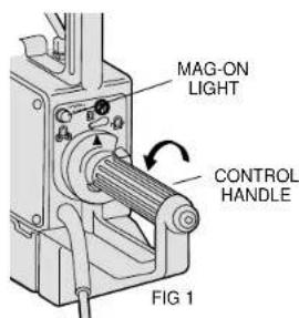
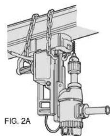
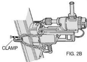
- Place drill press on work surface so that drill point or cutter pilot is directly over spot to be drilled. Pull trigger and twist control handle counterclockwise until MAG-ON light glows, indicating the magnet is energized. Figure 1. When drilling in an overhead or vertical position, the safety chain must be employed. See Figure 2A & 2B for two suggested positions. The use of a clamp between the chain loops as shown in
Figure 2B will prevent the mag press from falling when in the demag operation. (Clamp not included).
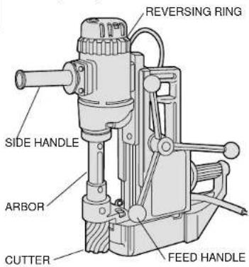
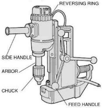
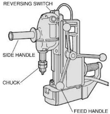
- (DW154, DW156) The motor switch is now aligned with a slot in the control handle, allowing the motor switch to be activated. Make sure reversing ring on top of motor is in the forward position. Figure 3. (On DW157 make sure reversing switch is in forward position).
- Gently apply pressure to feed handle until twist drill or cutter has a full bite (see special instructions for DW154) then apply steady pressure until cut is complete.
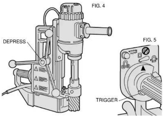
NOTE: The feed handle is quickly and easily reversible. Depress button in feed handle hub and remove handle. Insert in opposite side and release button. Figure 4.
- Turn off motor and allow motor to run down before turning magnet off.
- Turn magnet off by depressing trigger and turning control handle clockwise 45^ . Figure 5.
- After each use, rock unit back onto handle guard and remove all chips from magnet surface.
Operation of DW154 With D_EWALT Annular Cutters
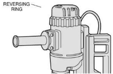
FIG. 3
- This unit was designed with user convenience and safety in mind
- User safety:
The switches are arranged to prevent the user from accidentally starting motor before the magnet is energized.
The handles are arranged to allow for easy vertical and overhead placement.
The switches are operated by a twist of the wrist.
- This unit comes equipped with a quick release feed handle. By simply depressing a button, the feed handle can be switched from the left to the right side of the unit.
- Continuous duty operation:
The motor units are the most rugged on the market.
5. Superior magnet power:
The magnet is designed to stay put on 1 / 2^n(13mm) flat steel or iron.
NOTE: DW156 can be adapted for use with annular cutters with addition of DW1559 Arbor Assembly. DW157 can be adapted for use with annular cutters with addition of DW1558 Arbor Assembly.
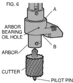
- Place proper pilot pin into desired cutter from the top and insert cutter into the arbor. Line up cutter flats with arbor set screws, Fig. 6. Tighten both set screws securely. (Make sure flats are properly located under set screws so that they remain recessed below surface of the shaft).
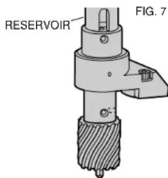
- Fill reservoir (slot in arbor) with DrWALT cutting fluid, Figure 7. This fluid is formulated to give the best performance and life to the rotary cutters. Fluid will be released down pilot shaft by gravity feed. Test by running cutter up and down against work surface to start fluid flowing. When cutting vertical or overhead, dip cutter in DeWALT cutting paste.
NOTE: This unit features an improved arbor bearing system. The bearings are lubricated at the factory. From time to time it is necessary to relubricate the bearings to insure efficient operation. Two holes are provided in the arbor bracket for this purpose as shown in Figure 6. If the drill press is used in a normal, upright position apply a liberal amount of SAE No. 20 or 30 oil at point A and in the holes. When drilling overhead, point B and the holes should receive the oil. If drilling horizontally, usually oil only needs to be applied through the holes. Apply the oil liberally at frequent intervals so that the bearing stays wet at all times.
- Start motor
9
1/2" (13 mm) THICK COLD ROLLED STEEL
FLAT SURFACE-ZERO AIR GAP
| Position | Percent of Maximum Drill Point Pressure |
| Horizontal | 100 |
| Overhead | 94 |
| Vertical with drill on top | 95 |
| Vertical with drill on bottom | 98 |
| Vertical with drill on side | 97 |
NOTE: Surface conditions will alter these readings.
They can be used for comparison purposes, but cannot always be duplicated.
English
Bring cutter lightly to the surface to be cut allowing 25-30 revolutions, bringing up light chip so that cutter has established an external groove. This will position you properly. Apply steady pressure through the entire cut. It is more important to keep rpm's up than to apply excessive force, causing cutter to slow motor down. This will attain better cutting action, better cutter life, and cleaner holes.
Slug should be expelled on the down stroke. If not, it will be expelled automatically when motor is returned to the extreme up position.
Operation (at 120 Volts AC)
Control
Apply sufficient pressure to get good drilling. Do not force unit. If magnet starts to lift from work plate, decrease pressure slightly and
| H.D. Magnet Drill Press | Nominal 700 lbs | Nominal 405 lbs | Nominal 180 lbs |
| Variation with Metal Thickness & Back up Plate | |||
| Plate Thickness | Back-Up Plate Thickness | % of Maximum Drill Point Pressure | |
| 1/4" (6 mm) | None | 41 | |
| 1/4" (6 mm) | 1/4" (6 mm) | 87 | |
| 1/4" (6 mm) | 3/8" (10 mm) | 94 | |
| 1/4" (6 mm) | 1/2" (13 mm) | 92 | |
| 5/16" (8 mm) | None | 57 | |
| 5/16" (8 mm) | 1/4" (6 mm) | 96 | |
| 5/16" (8 mm) | 3/8" (10 mm) | 98 | |
| 1" (25 mm) | None | 105 | |
| 1/4" (6 mm) | 1/4" (6 mm) | 51 | |
NOTE: Back-up Plate between magnet base and work piece.
it will reclamp. Drill point pressure may exceed holding power under one or more of the following conditions:
- Excessive air gap—1/64" (4mm) or more.
- Thin metal (under 1/2 (13mm) even with back up plate depending upon position and condition of metal surface.)
- Metal with low magnetic properties. 4. Uneven or rough surface.
- Low line voltage.
- Defective unit.
How To Drill & Tap
For accuracy drill a small lead hole before using the final size drill. Large diameter drills will "walk" off center until drill reaches full diameter at which point the outside diameter acts as a pilot in the hole being drilled. This is not peculiar to magnetic drill presses, but is general machine shop knowledge on any large hole drilling.
Adjustments
- This unit is designed with a permanently lubricated gib and is adjusted at the factory. The gib should be tight enough to retain the motor in the upward (retracted) position. Should this need adjustment, tighten 3 self-locking set screws,
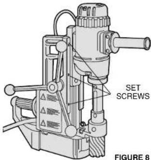
Figure 8.
- For user safety, this unit is equipped with a hardened tool steel torque pin located in the handle guard at the rear of the magnet. KEEP THIS PIN SHARP.
Should pin become dull, remove and resharpen as follows:
a. Replace new or resharpened torque pin by threading pin until it bottoms. (Run locknut to top of threads).
b. Place unit on smooth, flat surface.
c. Place A .015"(4mm) feeler gauge under magnet just forward of the torque pin.
d.Back torque pin down until it just touches surface.
e.Lighten locknut.
f. Check operation:
The pin should retract upward as control handle is turned to the off position.
Accessories
Recommended accessories for use with your tool are available at extra cost from your distributor or your local service center.
CAUTION: The use of any non-recommended accessory may be hazardous.
If you need assistance in locating any accessory, call us at:
1-800-4-DeWALT or contact DwALT Industrial Tool Co., 701 East Joppa Road, Baltimore, MD 21286
1. DW1559 arbor assembly for DW156.
2. DW1558 arbor assembly and thread adapter for DW157 only.
3. DW1560 3/4"(19mm) chuck and Adapter for DW154 only.
4. Mandrels and hole saws up to 2^ (51mm) diameter.
5. Rotary cutters and pilots 7/16" (11mm) thru 2" (51mm) diameter, DW154 only. (DW156 will take these cutters when fitted with arbor assembly).
- Twist drill bits 1/4" (6mm) to 13/16" (21mm)(DW156*) 5/64" (2mm) to 1/2" (13mm)(DW157)
- Taps 1/4'' (6mm) to 13/16" (21mm)(DW156*)
5/64"(2mm) to 1/2" (13mm)(DW157) - Reamers, Light Gauge 1/4" (6mm) to 5/8"(16mm)(DW156) Reamers, Heavy Gauge1/4" (6mm) to 1/2"(13mm)(DW156) DW154 will take these accessories when fitted with DW1560 chuck and adaptor.
Brushes
Carbon brushes should be regularly inspected for wear. When the cap is unscrewed, the spring and brush assembly may be withdrawn from the tool.
Keep brushes clean and sliding freely in their guides. Carbon brushes have varying symbols stamped into them, and if the brush is worn down to the line closest to the spring, they must be replaced. New brush assemblies are available at service centers; see back page of this manual.
Important
To assure product SAFETY and RELIABILITY, repairs, maintenance and adjustment (including brush inspection and replacement) should be performed by authorized service centers or other qualified service organizations, always using identical replacement parts.
Full Warranty
DrWALT heavy duty industrial tools are warranted for one year from date of purchase. We will repair, without charge, any defects due to faulty materials or workmanship. For warranty repair information, call 1-800-4-DrWALT. This warranty does not apply to accessories or damage caused where repairs have been made or attempted by others. This warranty gives you specific legal rights and you may have other rights which vary in certain states or provinces.
384946/DW154
9/25/00 1:27 PM Pa
English
In addition to the warranty, DeWALT tools are covered by our:
30 DAY NO RISK SATISFACTION GUARANTEE
If you are not completely satisfied with the performance of your DeWALT heavy duty industrial tool, simply return it to the participating seller within 30 days for a full refund. Please return the complete unit, transportation prepaid. Proof of purchase may be required.

384946/DW154 9/25/00 1:27 PM Page 9
POUR TOUT RENSEIGNEMENT SUPPLEMENTaire SUR CET OUTIL OU TOUT AUTRE OUTIL DE WALT, COMPOSER SANS FRAIS LE NUMERO:
18004-DEWALT(1800433-9258)

sue
9
| 6 mm (1/4") 10 mm (3/8") | 9 | 4 |
| 6 mm (1/4") 13 mm (1/2") | 9 | 2 |
| 8 mm (5/16") | 0 | 5 |
| 8 mm (5/16") 6 mm (1/4") | 9 | 6 |
| 8 mm (5/16") 10 mm (3/8") | 9 | 8 |
| 25 mm (1") 0 105 | ||
| 6 mm (1/4") 6 mm (1/4") | 5 | 1 |
Control
BOSQUES DE CIDROS ACCESO RADIATAS NO.42
COL. BOSQUES DE LAS LOMAS.
05120 MEXICO, D.F.
TEL:326-7100
Para增值服务ventas consulte
"HERRAMIENTAS ELECTRICAS