DW7461 - Sliding table DEWALT - Free user manual and instructions
Find the device manual for free DW7461 DEWALT in PDF.

| Product type | Sliding table for bench saw |
| Brand | DeWalt |
| Model | DW7461 |
| Compatibility | DeWalt DW746 bench saw |
| Main materials | Steel, alloy castings |
| Dimensions (assembled) | Approximately 1321 mm long (52-inch rails) |
| Weight | Not specified (heavy item, requires two people) |
| Kit contents | Sliding table, support hardware, rails, stabilizing legs, miter gauge with stop, T40 and T50 wrenches |
| Main functions | Extends cutting capacity, rip and miter cuts, precise guidance |
| Miter gauge | With adjustable stop, telescoping bar, detent for common angles |
| Adjustments | Table height, parallelism, miter gauge angle |
| Maintenance and cleaning | Clean ball slides with dry cloth, apply paste wax to prevent rust |
| Safety | Use eye protection, do not wear loose clothing, keep hands away from blade |
| Spare parts and repairability | Bolts, washers, screws, and hardware available at standard hardware stores |
| General information | Made for heavy-duty industrial applications, DeWalt warranty |
Frequently Asked Questions - DW7461 DEWALT
User questions about DW7461 DEWALT
0 question about this device. Answer the ones you know or ask your own.
Ask a new question about this device
Download the instructions for your Sliding table in PDF format for free! Find your manual DW7461 - DEWALT and take your electronic device back in hand. On this page are published all the documents necessary for the use of your device. DW7461 by DEWALT.
USER MANUAL DW7461 DEWALT
DEWALT Industrial Tool Co., 701 East Joppa Road, Baltimore, MD 21286
(FEB03)
Form No.394050-01
DW7461 Copyright © 1999,2000
Before returning this product call 1-800-4-DeWALT
IF YOU SHOULD EXPERIENCE A PROBLEM WITH YOUR DEWALT PURCHASE, CALL 1-800-4 DEWALT.
IN MOST CASES, A DEWALT REPRESENTATIVE CAN RESOLVE YOUR PROBLEM OVER THE PHONE.
IF YOU HAVE A SUGGESTION OR COMMENT, GIVE US A CALL.
YOUR FEEDBACK IS VITAL TO THE SUCCESS OF DEWALT'S
QUALITY IMPROVEMENT PROGRAM.
See our catalog on the World Wide Web. www.dewalt.com
INSTRUCTION MANUAL
GUIDE D'UTILISATION
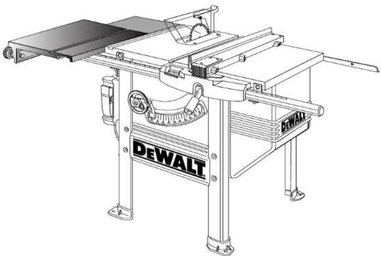
For Use Only With DEWALT DW746 Table Saw
Autiliserseulementaveclessciesa table DEWALT DW746
DEWALT high performance industrial tools are made for America's toughest Industrial and construction applications. The design of every tool in the line - from drills to sanders to table saws - is the result of rigorous use on job sites and throughout industry. Each tool is produced with painstaking precision using advanced manufacturing systems and intense quality control. Every tool is checked before it leaves the factory to make sure that it meets your standards for durability, reliability and power. DEWALT Built Job site Tough...WE GUARantee IT.
Hardware Included with the DW7461 Heavy Duty Slide Table
Items Included
(1) Slide Table sub-assembly
(1) Support bracket
- (2) Support rail
(3) Rear support bracket
(2) Stabilizing leg
(1) Miter gauge
(1) Miter gauge stop
(1) Miter gauge clamp
(1)Hardware bag
Tools Included
T orx T40 wrench
- Torx T50 wrench
Tools Needed
(2) 16mm or 5/8" open end wrench
13mm or 1/2" open end wrench
Ruler
- Soft hammer or regular hammer and block of wood
- Small flat blade screwdriver
Tospeed assembly, the following would be helpful:
- 16mm or 5/8" socket wrench
13mm or 1/2" socket wrench
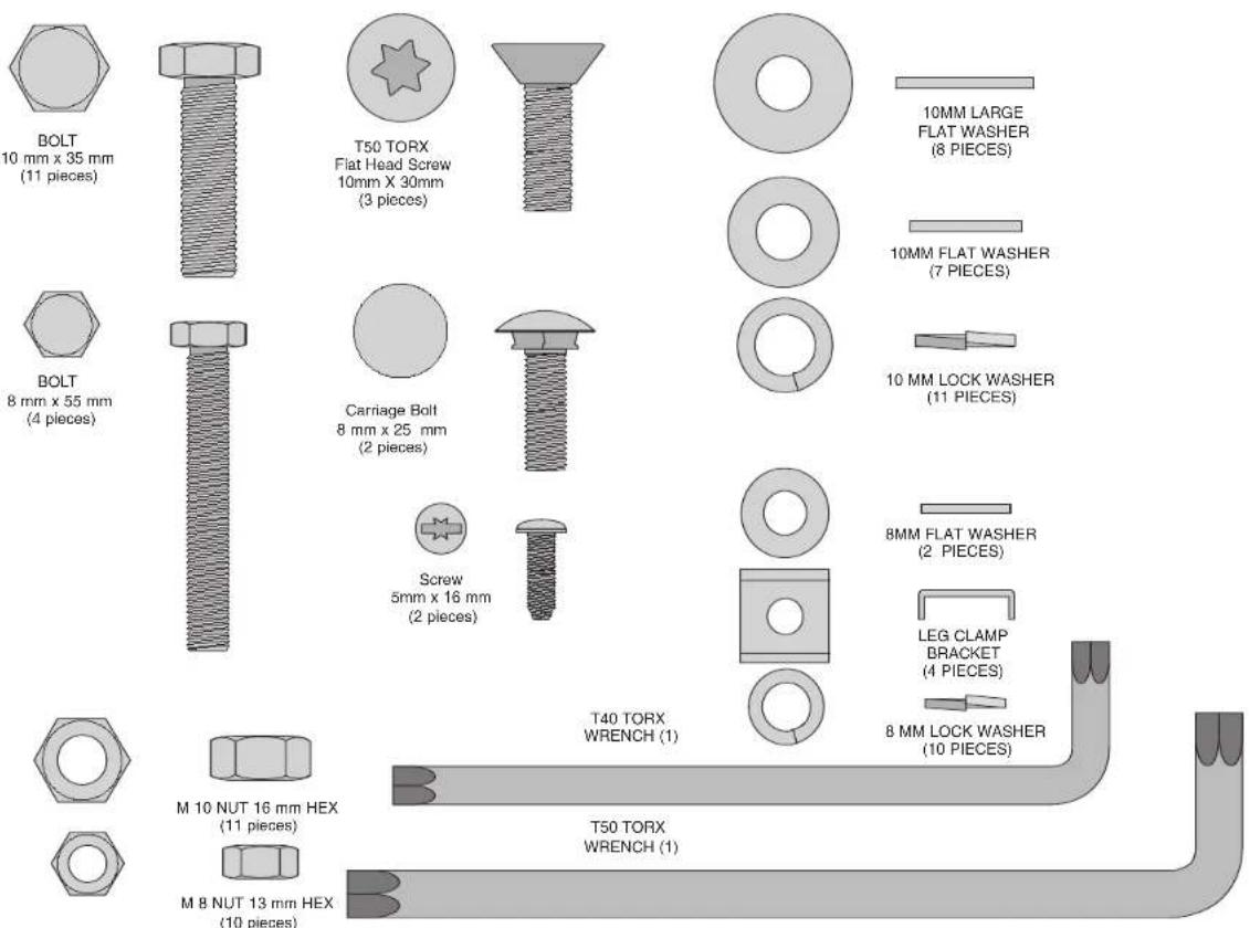
Necessary Hardware
The included hardware bag contains all the necessary nuts, bolts, and washers to assemble the components included with the DW7461 Slide Table and to attach it to the DW746 Woodworker's Table Saw (When attaching as an add-on use new hardware in place of removed hardware).
To make assembly of your saw/accessory easier, match the nuts, bolts, and washers with the hardware chart. Before each step, check your hardware against the chart and identify the pieces you need.
PLEASE READ ENTIRE ASSEMBLY SECTION
BEFORE PROCEEDING.
Assembly
If you have other accessories (52" Rail System and/or Outfeed Table) assemble the 52" Rail system first, except for attaching the front and rear rail. Then return to this manual at Step 16. Outfeed Table should be assembled last.
Table saw Preparation: If you are adding the DW7461 Sliding Table to an existing DW746 saw, disassemble the saw as described in steps 1 through 4. If your saw is not yet assembled, begin assembly with step 5.
STEP 1: Remove rear fence rail. Unbolt and remove the rear fence rail. If you have a 52^ rail system or an outfeed support table which uses mounting brackets to support the rail leave the brackets in place.
STEP2: Remove front fence rail. Remove the front fence rail from the mounting brackets by unscrewing the 8MM nuts on the bottom and lifting straight up.
STEP 3: Remove front rail brackets. Remove the fence rail mounting brackets from the saw by unscrewing the T50 flat head screws.
STEP 4: Remove left side support table. Loosen the three M10 bolts holding the left support table to the table saw. You can now lift the support table up and off. Finish removing the hardware.
IF THE SAW IS NEW, COMPLETE STEPS 5-11. IF NOT SKIP TO STEP 12.
STEP 5: If the saw is new, remove parts box, motor cover, fence beam, and side tables from saw packaging. Unpack rail carton containing front and rear rails.
STEP 6. If the saw is new, turn the saw right side up. You will need help. The combined weight of the table top and motor is approximately 200 lbs.
STEP 7. Cut and remove plastic strap holding the motor.
STEP 8. Using front hand crank, lower the motor some and remove the foam packing material between the motor and the mechanism.
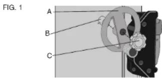
STEP 9. Install bevel crank (Fig. 1). To do this, first install the crank handle (A) over the shaft (B), rotate slightly to fully engage the shaft pin. Screw the lock knob (C) into place until it is fully seated, then back it off 1/4 to 1/2 tum.
STEP 10. Using height crank, raise mechanism up as high as it will go.
STEP 11. Install wrench hook (Fig. 2). On the front right leg, near the top is a plastic threaded insert. Thread the 'L' shaped wrench hook in
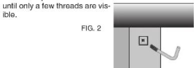
2
STEP 12. Unpack Slide Table carton.
STEP 13. Replace table saw leg screws (Fig. 3).
You will need: 4 - 8 x 55mm hex head bolts
4-8mm lock washers
4-8mm nuts
Working on one bolt at a time, remove M8 cap screws and replace with an M8 x 55 hex head bolt (Do not remove all M8 cap screws at the same time.) Install bolt from the inside of the table saw and secure with a lock washer and nut, fully tighten and insure that washer and nut are within the depression on the leg. Continue, one at a time, until all four M8 bolts on the left side of the saw have been replaced.
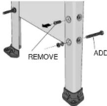
FIG. 3
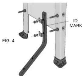
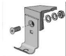
STEP 14. Install stabilizing legs on saw.
You will need: 4 - Leg clamp brackets
4-8mm lock washers
4-8mm nuts
The legs can be installed in either of two positions depending on whether you are using a mobile base (DW7460). Without the mobile base, the legs are installed with the identification mark (hole) toward the top as shown in figure 4. If a mobile base is installed, then the identification mark is toward the bottom. Secure the stabilizing legs to the saw using the leg clamp brackets, lock washers, and nuts. Snug the nuts, but do not tighten.
STEP 15. Adjust stabilizing legs by sliding them down until they contact the floor. Tighten hardware securely. STEP 16. Attach right side support table (Fig.5). (If the support table is already installed or you have a 52^ Rail System, skip this step.)
You will need: 3 - 10 x 25mm hex head bolts
3 - 10mm flat washers
3-10mm lock washers
Without the support table in place, install the 3 bolts in the right side with washers as shown keeping 1/4^ gap. Rest a support table on the bolts, fitting into the notches. Using the extruded fence face as a straightedge, flush the support table to the saw table edge and snug the front bolt. Repeat this process for the rear bolt and the center bolt. Tighten hardware securely.
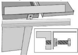
FIG.5
STEP 17. Install slide rail bolts to front fence mounting brackets. (Fig. 6)
You will need: 2 - fence rail mounting brackets
2 - 8 x 25mm carriage bolts (no wahers or nuts at this time)
2 - small pieces of tape
Insert the two 25mm carriage bolts through the square holes on the flat side of two of the mounting brackets. The head of the bolt should face forward as shown in Fig. 5. Temporarily hold them in place with a piece of tape. This is done before mounting the brackets to the rail, because you will not be able to insert these bolts afterwards.
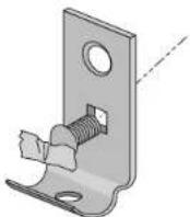
FIG.6
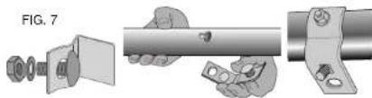
STEP 18. Install mounting brackets to fence rail tube (Fig. 7). You will need:
3-8x20mm carriage bolts
3 - 8mm lock washers
3-8mm nuts
3 - mounting brackets (2 from step 17 above plus one more)
(Your saw is shipped with four fence rail mounting brackets, but the left most bracket is not used with the sliding table attachment, and can be set aside.)
Place the fence rail tube so that the scale reads correctly.
Insert the three 20mm carriage bolts through the holes on the curved face of each mounting bracket, and loosely place a lock washer and nut on them. Put the head of each carriage bolt into the keyhole slot of the fence rail and slide them sideways to engage. The two brackets with the additional carriage bolt taped in place, are used for the middle keyholes. The third bracket is used in the right most keyhole. Make sure all three brackets face toward the rear of the fence rail. Snug the nuts up, but do not tighten them all the way.
STEP 19. Attach fence rail tube to saw (Fig. 8 and 9). You will need:
2 - 10 x 30mm flat head screws
2-10mm flat washers
2-10mm lock washers
2-10mm nuts
Secure the middle two brackets of the fence rail tube to the table saw top using the screws, washers, and nuts. The washers and nuts should be on the inside edge of the table. Snug the nuts, but do not tighten them.
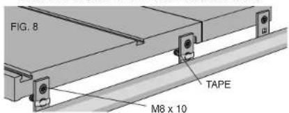
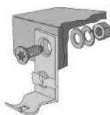
FIG.9
English
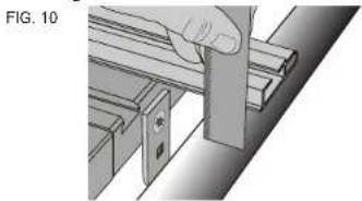
STEP 20. Parallel the front fence rail tube to the saw table (Fig. 10). Before you adjust the height of the fence rail tube, tighten the two nuts that hold the tube to the mounting brackets.
Place a straight edge on the table extending out over the rail tube (you can use the aluminum fence from your saw as a straight edge). Using a ruler and this straight edge, check to see if both ends of the rail tube are the same distance below the table. If you need to raise or lower one side of the tube, use a rubber mallet, or a hammer and a block of wood to prevent denting the tube and tap on the rail gently. Fully tighten the mounting bolts.
STEP21. Attach front rail bracket to support table (Fig. 11)
(If you have a 52^ Rall System, skip this step)
You will need: 1 - 10 x 30mm flat head screw
1-10mm flat washer
1-10mm lock washer
1-10mm nut
Align front bracket with the support table and tighten bracket nuts to the rail. Attach the support table to the outer front rail support bracket, keeping the washers and nut on the inside of the table. Using the fence face as a straight edge, make sure the front outer corner of the support table is level with the inner edge and main table surface. Tighten hardware, including the 8mm rail support bracket nut.
FIG. 11
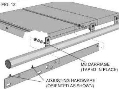
STEP 22. Install front Silde Table support rails. (Fig. 12)
You will need: 2 - 8mm flat washers
2-8mm lock washers
2-8mm nuts
Examine the two sliding table support rails to determine which one is for the front and which one is for the rear. The front rail will have the height adjustment screws to the left side, and behind the face as shown.
The sliding table front rail is secured to the backside of the front fence rail mounting brackets using the carriage bolts temporarily taped in place previously. Position the front rail over the taped carriage bolts, and add the washers and nuts. Snug the nuts down, but do not tighten.
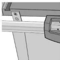
STEP 23. Attach slide table support bracket (Fig. 13).
You will need: 3 - 10 x 30mm flat head screws Place tab on the end of the support bracket through the rectangular hole in the slide table support rail, line up countersunk holes in support bracket with threaded holes in side of table saw table. Using the included T50 torx wrench, install three M10 x 30 screws directly into the table, no washers or nuts needed. Tighten securely. Ensure that the screw heads are flush with or recessed below the bracket surface.
FIG. 13
STEP 24. To prevent the rail from sagging over time and causing misalignment with the slide table, pre-stress the rail downward. Apply downward pressure to left end of front slide table support rail so right end will rock up into contact with underside of table saw table. Fully tighten nuts on M8 carriage bolts.
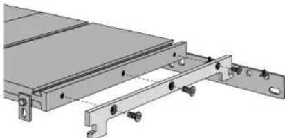
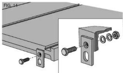
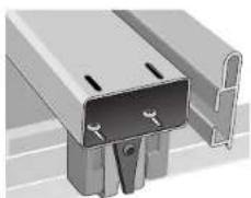
STEP 25. Install rear mounting brackets. (Fig. 14) You will need: 3 - flat mounting brackets
3 - 10 x 35mm hex head bolts
3 - 10mm flat washers
3-10mm lock washers
3-10mm nuts
If you have either the 52^ fence accessory or the outfeed support table, you can use the existing supports instead of installing a new one. Skip this step.
Attach the two mounting brackets to the tablesaw top using the bolts, washers, and nuts, as shown in Fig. 14. Tighten securely. The brackets are mounted using the round holes, and the slotted holes will hang below the table top.
Attach the third mounting bracket to the rear of the right hand support table. The bracket is mounted using the round hole into the slot in the support table.
When tightening nuts, keep the brackets positioned square to the table.
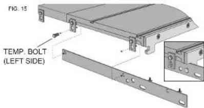
STEP 26. Install the rear sliding table support rail. (Fig. 15)
You will need: 2 - 10 x 35mm hex head bolts
2-10mm flat washers
2-10mm lock washers
2-10mm nuts
The rear sliding table support rail mounts inside the brackets installed previously, and also locks onto the tab of the support bracket similar to the way the front rail is mounted. Temporarily insert the left side bolt and nut to support the rail until you position the rear fence support rail in the next step.
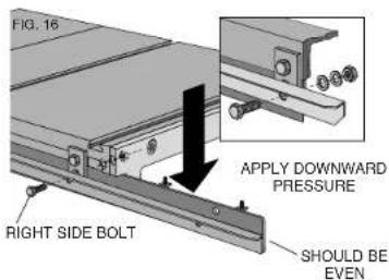
STEP 27. Install the rear fence support rail (Fig. 16).
If you are installing the sliding table to an existing saw, take note that the rear fence support rail is inverted from your original installation. The fence support rail uses the same bolts as the sliding table support rail, but is mounted on the outside of the brackets. Install the right-hand bolt, washers and nut, and snug them up without tightening. Remove the temporary bolt from the left-hand bracket you installed above, and reinsert it through the fence support rail bracket, and sliding table support rail. The right-hand end of the fence support rail should be even with the sliding table support rail.
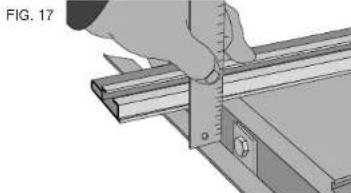
STEP 28. Tighten rear rail and slide table support bracket (Fig. 17). Facing the back of the saw, apply downward pressure to right end of slide table support rail so left end will rock up into contact with underside of table saw table. Lift up on rear fence support rail next to left hand support bolt. Tighten hardware securely. Place a straight edge (the alminum fence supplied) on the table extending out over the rear fence support rail. Using a ruler and this straight edge, set the right side of the rear fence support rail the same distance from the table surface as the left hand side. Tighten right hand hardware securely.
STEP 29. Attach rear fence support rail to right support table.
You will need: 1 - 10 x 35mm hex head bolt
1-10mm flat washer
1-10mm lock washer
1-10mm nut
Attach the rear fence support rail to the support bracket keeping the washers and nut to the inside. Using the fence face as a straight edge, make sure the rear outer corner of the support label is level with the inner edge and main table surface. Tighten hardware securely.
STEP 30. Attach slide lock knob assembly (Fig. 18).
You will need: 2 - 5 x 16mm pan head screws Set slide lock knob to "un-locked" position (pin most retracted). Align mounting holes in lock knob housing with the threaded holes in the slide table. Tighten screws. Return knob to "locked" position, lock will automatically engage and lock table.
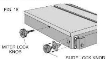
STEP 31. Attach miter lock knob (Fig. 18). Screw lock knob assembly into threaded hole in the slide table until hand tight.
INSTALLSLIDETABLEONTOSSUPPORTRAILS:
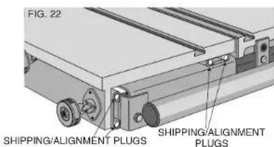
STEP 32. Slides in slide table are equipped with shipping/alignment plugs to limit slide movement.
IMPORTANT: DO NOT remove shipping/alignment plugs before slide table is fully installed.
STEP 33. Slide table is heavy. Use extreme caution when lifting. Use two people to lift slide table.
STEP 34. Lift slide table out of shipping box and place onto support rails.
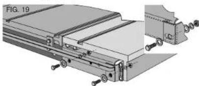
STEP 35. You will need: 4 - 10 x 35mm hex head bolts
8-Large 10mm flat washers
4-10mm lock washers
4-10mm nuts
In front of saw, place a large M10 washer on each bolt. Install bolts through slots in slide table support pan and support rails. In rear of saw, place a large M10 washer between rear fence rail and slide table support pan. (Fig. 19). Secure each bolt with a large M10 washer, lock washer, and nut. Loosely tighten nut, then back off one full turn. It may be necessary to align the flats on the hex bolts with the rear rail.
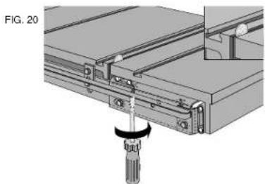
STEP 36. Align slide table to saw table (Fig. 20). Prior to adjustment, place the saw in its final location. Insure that shipping/alignment plugs are in place. Using a coin, fooler gauge or thick paper as a shim, push the sliding table toward the saw table, but leave a clearance gap between them. The size of the gap is not important, but should be relatively small and the two tables should be parallel.
Adjust the height of the sliding table so it is approximately flush with the table saw top. The height adjustment screws are on the front and rear support rails. Before completing the final height adjustment of the table, tighten the four mounting bolts to seat them in their holes, but then loosen them again so the final adjustment can be made. The bolts need to be loose enough to allow the brackets to move up and down as the height adjustment screws are turned.
STEP 37. Adjusting the height of the sliding table. (Fig. 21) Prior to adjustment, insure that shipping/alignment plugs are in place. Place a straight edge across the tablesaw top and extended over the sliding table top. Adjust the height of the sliding table by turning the screws clockwise to raise the sliding table until it is just slightly higher than the tablesaw top. If you need to back the adjustment screws out, make sure you press down on the table to ensure it is seated on the top of the screws.
When the height is correct, tighten the four mounting bolts and re-check both the height and the side clearance with respect to the tablesaw top. Readjust as necessary.
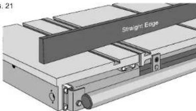
FIG. 21
STEP 38. Remove shipping/alignment plugs (Fig. 22).
This can be done by unlocking slide lock and giving the slide table a firm push. Once shipping/alignment plugs are removed, slide table should move freely. Save shipping/alignment plugs, if slide table needs future adjustment, is to be removed from saw, or is to be transported, reinstall shipping/alignment plugs by lightly tapping plugs into end of ball bearing slide with small mallet.
Finish Table Saw Assembly:
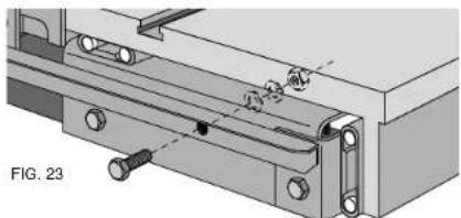
Attach rear fence rail to Slide Table support pan (Fig. 23).
You will need: 1 - 10 x 35mm hex head bolt
1-10mm flat washer
1-10mm lock washer
1-10mm nut
Secure bolt with a flat washer, lock washer, and a nut. Tighten hardware snug.
STEP 39. Re-check parallel of rails to the saw table top (Fig. 17). Using your fence face or a straightedge to extend the table surface over the rear fence rails, make sure the distance from the saw table top to the rail top is the same at both the left and right side of the saw table. If a rail is not aligned correctly, loosen all mounting screws slightly and tap on the rail with a soft hammer or a regular hammer and a block of wood until the distances are the same. Tighten the hardware attached to the saw table securely. Repeat for the remaining attachment points checking the distance along the full length of the rail.
STEP 40. See DW746 manual for Table Saw operating Instruction and adjustments.
Miter Guage Assembly
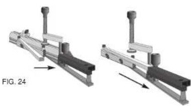
STEP 41. Insert telescoping scale into housing. Arrange miter gage as shown in Fig.24. Insert telescoping scale bar into the housing. Align 90^ mark with end of outer housing. Tighten clamp.
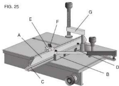
Miter Gauge Assembly - Fig. 25:
STEP 42. Attach fence to miter gauge. Loosen wing nuts (D). Orient fence (A) and slide miter gauge (B) locking bar to slot (C) in fence. Tighten thumb screws (D) to lock fence into place, loosen thumb screws to adjust.
STEP 43. Attach adjustable stop (E) to miter fence. Slide adjustable stop locking hardware (F) into slot on top of the fence. Tighten thumb screws to lock fence into place, loosen thumb screws to adjust.
STEP 44. Attach quick release clamp (G) to miter gauge. Put locking screw in full-up position. Orient clamp pointing rearward and drop into top of miter gauge. Turn clamp 180 degrees to retain.
Miter Gauge Use
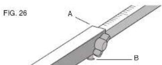
Adjust miter gauge angle - Fig. 26
Align mark on telescoping bar with end of housing (A). Tighten thumb screw.
Angle Detent System - Fig. 26
The miter gauge is equipped with a detent system for easily settling the more frequently used angles. Adjust miter gauge in the vicinity of the angle desired, press and hold detent button (B) on bottom of beam and slide scale in until the detent catches. Tighten thumb screw.
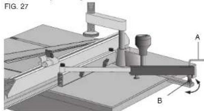
Miter Gauge Calibration - Fig. 27
- Set the miter gauge to 90^ using the detent system.
- Loosen eccentric lock screw (A). Inside housing using hex key.
- Turn eccentric (B) to adjust gauge to true 90^ using calibration square. Tighten eccentric lock screw.
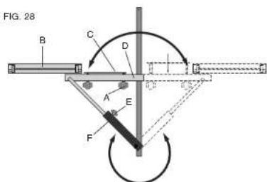
Reversing Miter Gauge - Fig. 28
The Miter Gauge can be reversed easily.
- Loosen fence lock knobs (A), remove fence (B).
- Remove lock knobs and fence clamp (C) from fence base (D).
- Loosen telescoping clamp (E) and pull angle scale out of housing.
- Rotate telescoping housing (F) to oposite side.
- Rotate fence base to other side.
- Re-enage degree scale into housing.
- Re-install fence clamp and lock knobs.
- Re-install fence and tighten clamp.
Operation of Slide Table
- Install miter gauge in "T" slot in slide table in desired location and angle. Adjust miter gauge fence approximately 1" from blade.
- Tighten miter gauge lock knob on left side of slide table.
- Move slide table toward operator and ensure that work piece will clear blade. Cycle slide table and ensure that end of miter gauge fence goes past blade centerline and does not contact blade or blade guard.
- Move slide table toward operator, place work piece on slide table. Engage hold down clamp if needed. If using flip stop, hold piece securely against flip stop and miter gauge fence. Keep hold down clamp centered over miter gauge bar. Do not overtighten clamp.
- Turn on saw. Push slide table and work piece through blade. Do not stand directly behind blade.
- Turn off saw. Remove work piece. Return slide table to home position.
Adjust the rear fence glide
If necessary, adjust the rear glade to locate it correctly against the rear rail by loosening the two screws which secure it to the fence beam. The plastic retaining clip should be deflected somewhat when the glide is positioned correctly. This adjustment should only be necessary if the rear rail has been relocated by the addition of an optional accessory.
Cleaning
Cleaning Slides:
STEP 1. Push Slide Table rearward as far as it will go. Gently sweep sawdust off of slide table support pan. Return slide table to its parked position.
STEP 2. To clean ball bearing slides, move slide table as far forward as it will go. Using clean rag, gently wipe exposed ball tracks on slides attached to support pan. Look under slide table, gently wipe exposed ball tracks on slides attached to underside of table. Push slide table as far as it will go in other direction. Again, wipe exposed ball tracks on slides attached to support pan and underneath table.
Cleaning Slide Table:
- Protect your investment. Keep your slide table clean. If you notice signs of rust on the table, steel wool the areas. Clean with mineral spirits or denatured alcohol and apply paste wax.
A VERTISSEMENT : POUR VOITRE PROPRIE SECURITE, LIsez LE GUIDE D'UTILISATION AVANT D'UTILISER LA SCIE • PORTEZ TOUJOURS DES LUNETIES DE PROTECTION DLS YEUX • NE PORTEZ PAS DE GANTS, DE CRAVATE, DE BIOLX OU DE VETEMENTS AMPLES • ATTACHEZ VOS CHEVEUX S'SS SONT LONGS • GARZEZ VOs MAINS ET VOs DOIGTS HORS DU TRAJET DE LA LAME - FAITES EXTRÉMÈTMENT ATTENTION SI VOUS BISLAUTEZ • UTILISEZ TOUJOURS LE PROTECTOR DE LA LAME ET L'ÉCARTEUR POUR TOUTE OPÉRATION POUR LAQUELLE IL PEUT ÉTRÉ UTILISÉ Y COMPRIS SCIER • UTILISZ UN • POUSSOR • AU BesOIN • SACHZ ÉTTTER LES REBONDS - VOIR LE GUIDE • SOUTENZ TOUJOURS VOITRE TRAVAIL AVEC LA TABLE ET LE GUIDE OU LE CALIBRE À ONGLETS • N'UTILISZ JAMAIS LE GUIDE ET LE CALIBRE À ONGLETS ENSEMBLE • NE PASSEZ JAMAIS LA MAIN AUTOUR OU AU DESSUS DE LA LAME • MONTEZ BIGN LA LANE AVANT DE L'UTILISER • NE RETIREZ JAMAIS DES MORCEAUX COINÇES OU COUPÉS TANT QUE L'ALIMENTATION N'EST PAS ÉTEINTE ET QUE LA LANE N'EST PAS ARRÊTÉE · N'EXPOSEZ PAS CET OUTFIL À LA PLUÉ ET NE L'UTILISZ PAS DANS DES LIEUX IUMIDES • NE LE FAITES PAS FONCTIONNER EN CAS D'ÉTAT D'EBRIÉTÉ OU D'ÉTAT DROGUE • MANQUER DE RESPECTER THESE CONSIGNES PEUT RÉSULTER DANS DES BLESSURES GRAVES.
A VERTISSEMENT: L'UTILISATION DE CET OUTFIL POTUER GENERER DES POUSSIÈRES CONTENANT DES PRODUITS CHIMiques CONNUS POUR ÉTRE À L'ORIGINE DE CANCERS, DE MALFORMATIONS CONGENITALES OU AUTRES ENDOMMAGEMENTS DU SYSTÉME REPRODUCTIF. UTILISEZ UN APPAREIL RESPIRATOIRE APPROPRIÉ.