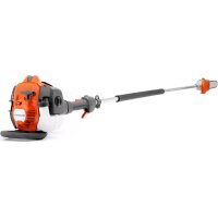
525P4S - Saw HUSQVARNA - Free user manual and instructions
Find the device manual for free 525P4S HUSQVARNA in PDF.



| Product Type | Gas Pole Saw |
| Brand | Husqvarna |
| Model | 525P4S |
| Displacement (cm³) | 25,4 |
| Max Power (kW/rpm) | 1,0 / 8 500 |
| Idle Speed (rpm) | 2 800 - 3 000 |
| Max Overspeed (rpm) | 11 000 - 12 000 |
| Weight without fuel or cutting equipment (kg) | 5,3 |
| Fuel Tank Capacity (L) | 0,5 |
| Chain Oil Tank Capacity (L) | 0,2 |
| Spark Plug | NGK BPMR8Y |
| Electrode Gap (mm) | 0,65 |
| Sound Power Level (dB(A)) | 107 |
| Vibration Levels (m/s²) front/rear | 3,6 / 3,5 |
| Recommended Chain Types | Husqvarna H37 or S93G |
| Guide Bar Lengths (cm/in) | 25/10 or 31/12 |
| Chain Pitch (in) | 3/8 |
| Chain Gauge (mm/in) | 1,3 / 0,050 |
| Chain Lubrication | Automatic with adjustable flow |
| Harness Included | Yes, model 525P4S |
| Catalytic Converter Muffler | Yes |
| Shaft Length | Fixed (non-detachable) |
| Model 525P5S (detachable shaft) | No, this is the model 525P5S |
Frequently Asked Questions - 525P4S HUSQVARNA
User questions about 525P4S HUSQVARNA
0 question about this device. Answer the ones you know or ask your own.
Ask a new question about this device
Download the instructions for your Saw in PDF format for free! Find your manual 525P4S - HUSQVARNA and take your electronic device back in hand. On this page are published all the documents necessary for the use of your device. 525P4S by HUSQVARNA.
USER MANUAL 525P4S HUSQVARNA
EN Operator's manual 2-27
Transportation, storage and disposal.... 23
Technical data.... 24
Accessories.... 25
EC Declaration of Conformity.... 27
Introduction
Intended use
The product is used for cutting branches and twigs.
Note: National regulations can set limit to the operation of the product.
Only use the product with accessories that are approved by the manufacturer. Refer to Accessories on page 25.
Product overview

- Chain lubrication adjustment screw
- Shaft
- Front handle
- Throttle trigger
- Stop switch
- Throttle trigger lockout
- Harness support hook
- Cylinder cover
-
Starter handle
-
Fuel tank
- Choke control
- Air purge
- Air filter cover
- Protective guard for saw chain
- Bar nut
- Saw chain
- Guide bar
-
Chain tensioning screw
-
Chain oil tank
- Operator's manual
- Transport guard, bar
- Hex key
- Combination wrench
- Combination wrench, chain tensioner
- Harness 525P5S
- Harness 525P4S
- Shaft coupling
- Impact guard
- Spark plug cap and spark plug
Symbols on the product

WARNING! This product is dangerous. Injury or death can occur to the operator or bystanders if the product is not used carefully and correctly. To prevent injury to the operator or bystanders, read and obey all safety instructions in the operator's manual.

Please read the operator's manual carefully and make sure that you understand the instructions before use.

Use a protective helmet in locations where objects can fall on you. Use approved hearing protection. Use approved eye protection.

Use approved protective gloves.

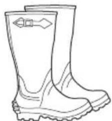
Use heavy-duty slip-resistant boots.
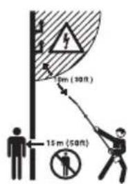
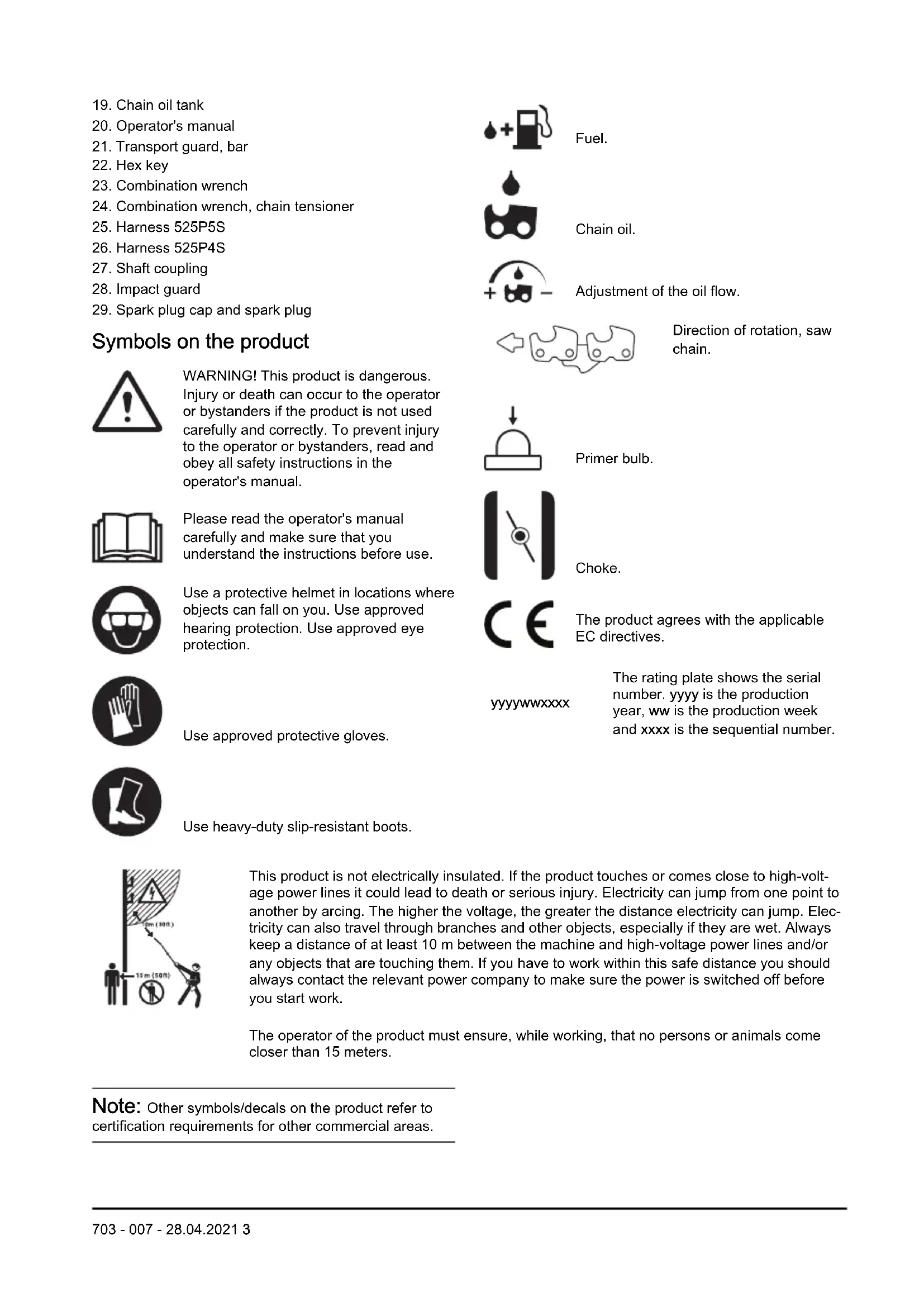
This product is not electrically insulated. If the product touches or comes close to high-voltage power lines it could lead to death or serious injury. Electricity can jump from one point to another by arcing. The higher the voltage, the greater the distance electricity can jump. Electricity can also travel through branches and other objects, especially if they are wet. Always keep a distance of at least 10 m between the machine and high-voltage power lines and/or any objects that are touching them. If you have to work within this safe distance you should always contact the relevant power company to make sure the power is switched off before you start work.
The operator of the product must ensure, while working, that no persons or animals come closer than 15 meters.
Note: Other symbols/decals on the product refer to certification requirements for other commercial areas.

Fuel.

Chain oil.

Adjustment of the oil flow.

Direction of rotation, saw chain.

Primer bulb.

Choke.

The product agrees with the applicable EC directives.
yyyyMMddxxxx
The rating plate shows the serial number. yyyy is the production year, ww is the production week and xxxx is the sequential number.

WARNING: Tampering with the engine voids the EU type-approval of this product.
Product liability
As referred to in the product liability laws, we are not liable for damages that our product causes if:
• the product is incorrectly repaired.
- the product is repaired with parts that are not from the manufacturer or not approved by the manufacturer.
- the product has an accessory that is not from the manufacturer or not approved by the manufacturer.
- the product is not repaired at an approved service center or by an approved authority.
Safety
Safety definitions
Warnings, cautions and notes are used to point out specially important parts of the manual.

WARNING: Used if there is a risk of injury or death for the operator or bystanders if the instructions in the manual are not obeyed.

CAUTION: Used if there is a risk of damage to the product, other materials or the adjacent area if the instructions in the manual are not obeyed.
Note: Used to give more information that is necessary in a given situation.
General safety instructions

WARNING: Read the warning instructions that follow before you use the product.
- This product produces an electromagnetic field during operation. This field may under some circumstances interfere with active or passive medical implants. To reduce the risk of serious or fatal injury we recommend persons with medical implants to consult their physician and the medical implant manufacturer before operating this product.
- This product is a dangerous tool if you are not careful or if you use the product incorrectly. This product can cause serious injury or death to the operator or others.
- It is very important that you read and understand the contents of this operator's manual. If you feel uncertainty about a work situation or the operating procedures after you read the operator's manual, speak to a service agent before you continue.
- Under no circumstances may the design of the product be modified without the permission of the manufacturer. Do not use a product that appears to have been modified by others and only use
accessories recommended for this product. Non-authorized modifications and/or accessories can result in serious personal injury or the death of the operator or others.
- Do a check of the product before use. Refer to Safety devices on the product on page 6 and To check before starting on page 11. Do not use a defective product. Do the safety checks, maintenance and service instructions described in this manual.
Safety instructions for assembly

WARNING: Read, understand and obey these instructions carefully before you use the product.
- The complete clutch cover and shaft must be fitted before the machine is started, otherwise the clutch can come loose and cause personal injury.
- The only accessories you can operate with this product are the cutting attachments we recommend. Refer to Accessories on page 25.
- Use approved protective gloves.
- Make sure that you assemble the protective cover and shaft correctly before you start the engine.
• To operate the product safely and prevent injury to the operator or other persons, the product must always be attached correctly to the harness.
Safety instructions for operation

WARNING: Read the warning instructions that follow before you do maintenance on the product.
- Use personal protective equipment, refer to Personal protective equipment on page 5.
- This product is not electrically insulated. If the product touches or comes close to high-voltage power lines it could lead to death or serious bodily injury. Electricity can jump from one point to another by arcing. The higher the voltage, the greater the distance electricity can jump. Electricity can also travel through branches and other objects, especially if they are wet. Always keep a distance of at least 10
m between the product and high-voltage power lines and/or any objects that are touching them. If have to work within this safe distance you should always contact the relevant power company to make sure the power is switched off before you start work.
• Overexposure to vibration can lead to circulatory damage or nerve damage in persons who have poor circulation. Speak to your physician if you experience symptoms of overexposure to vibration. Such symptoms include numbness, loss of feeling, tingling, pricking, pain, loss of strength, changes in skin colour or condition. These symptoms usually show in the fingers, hands or wrists. The risk increases at low temperatures.
- The inside of the muffler contain chemicals that may be carcinogenic. Avoid contact with these elements in the event of a damaged muffler. Long term inhalation of the engine's exhaust fumes, chain oil mist and sawdust can represent a health risk.
- Never use the machine indoors or in spaces lacking proper ventilation. Exhaust fumes contain carbon monoxide, an odourless, poisonous and highly dangerous gas.
- Do not operate a product without a muffler or with a defective muffler. A defective muffler can increase the noise level and the risk of fire. Keep fire extinguishing tools near. If you must have a spark arrestor mesh in your area, do not use the product without or with a broken spark arrestor mesh.
- If the saw chain does not stop when idling, adjust the idle speed. Refer to To adjust the idle speed on page 16. Do not use the product until it is correctly adjusted or repaired.
- This product has a long reach. Make sure that no people or animals come closer than 15 m when the product is running. Always look behind you before you turn around with the product. Stop the product immediately if a person or animal enters the 15 m safety zone. If more than one operator does work in the same area, keep a safety distance of a minimum of 15 m.
- Observe the applicable safety regulations for work in the vicinity of overhead power lines. Also falling branches can result in short-circuiting.
- Never stand directly underneath a branch that is being cut. This could lead to serious or even fatal personal injury.
- Watch out for stumps of branches that can be thrown out when you cut. Do not cut too close to the ground where stones and other objects can be thrown out.
- Do not operate the product in bad weather, such as dense fog, heavy rain, strong wind and intense cold. To operate in bad weather can make you tired and add risks, such as icy ground and unpredictable felling direction.
- Do not use the product if you are tired, ill, or under the influence of alcohol, drugs or medicine, as this has a negative effect on your vision, alertness, coordination and judgment.
- Make sure that you can move safely and have a safe stance. Examine the area around you for obstacles such as roots, rocks, branch and ditches. Be careful during work on slopes.
- Do not remove the cut material, or let other persons remove cut material, while the engine is on or the cutting equipment rotates, as this can result in serious injury.
- Do not overreach. Keep a stable position of the feet and a good balance at all times.
• Always hold the product with both hands. Hold the product on the right side of your body.
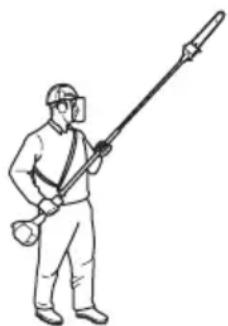
- Keep your hands and feet away from the saw chain until it has stopped completely when the product is deactivated.
- Never work from a ladder, stool or any other raised position that is not fully secured.
- Do not put the product down with the engine on unless you have it in clear view.
- Listen for warning signals and loud voices when you use hearing protection. Always remove your hearing protection when the engine stops.
- Stop the engine before you move to a new work area. Always attach the transport guard before you move the equipment.
- Never allow children to use or be in the vicinity of the product. Remove the spark plug cap when the product is not under close supervision.
Personal protective equipment

WARNING: Read the warning instructions that follow before you use the product.
• Always use approved personal protective equipment when you use the product. Personal protective equipment cannot fully prevent injury but it decreases the degree of injury if an accident does occur. Let your dealer help you select the right equipment.
- Use a protective helmet where there is a risk of falling objects.
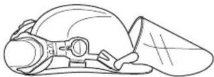
- Use approved hearing protection that provides adequate noise reduction. Long-term exposure to noise can result in permanent hearing impairment.

- Use approved eye protection. If you use a visor, you must also use approved protective goggles. Approved protective goggles must comply with the ANSI Z87.1 standard in the USA or EN 166 in EU countries.

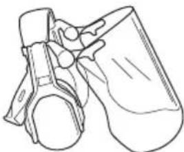
- Use gloves when necessary, for example when you attach, examine or clean the cutting equipment.

- Use sturdy non-slip boots.
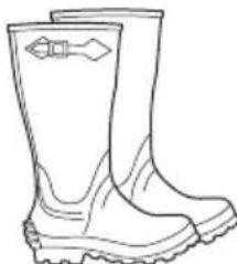
- Use clothing made of a strong fabric. Always use heavy, long pants and long sleeves. Do not use loose clothing that can catch on twigs and branches. Do not wear jewelry, short pants, sandals or go with
bare feet. Put your hair up safely above shoulder level.
- Keep first aid equipment close at hand.

Safety devices on the product

WARNING: Read the warning instructions that follow before you use the product.
- Do not use a product with defective safety devices.
- Do a check of the safety devices regularly. Refer to Maintenance schedule on page 15.
- If the safety devices are defective, speak to your Husqvarna servicing dealer.
To do a check of the throttle trigger lockout
The throttle trigger lockout prevents accidental operation of the throttle control.
- Push the throttle trigger lockout (A) and make sure that the throttle control is released (B). When you release the handle, the throttle control and the throttle trigger lockout move back to their initial positions.

- Release the throttle trigger lockout and make sure that the throttle control is locked at idle speed.

- Push the throttle trigger lockout and make sure that it goes back to its initial position when you release it.

- Make sure that the throttle control and throttle trigger lockout move freely and that the return springs operate correctly.

-
Start the product and apply full throttle. Refer to To start the product on page 14.
-
Release the throttle control and make sure that the cutting attachment stops. If the cutting attachment rotates with the throttle in the idle position, do a check of the carburetor adjustments. Refer to Maintenance on page 15.

To do a check of the stop switch
-
Start the engine.
-
Move the stop switch to the stop position and make sure that the engine stops.

To do a check of the vibration damping system
The vibration damping system decreases vibration in the handles to a minimum which makes the operation
easier. The vibration damping system of the product decreases the transfer of vibration between the engine unit and the shaft unit of the product.
- Stop the engine.
- Do a visual check for deformation and damage, for example cracks.

- Make sure you attach the elements of the vibration damping system correctly.
To do a check of the muffler
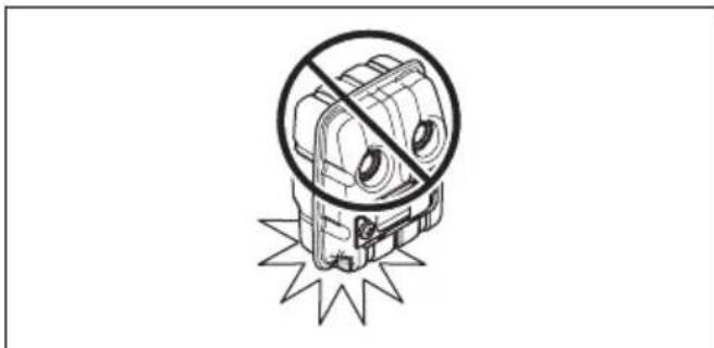
The muffler keeps noise levels to a minimum and directs exhaust fumes away from the operator. In areas with a hot, dry weather there is a high risk of fire. Obey local regulations and maintenance instructions
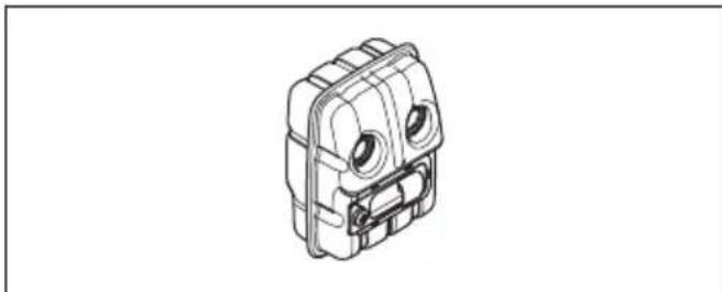
- Do a visual check for damage and deformation.
- Make sure that the muffler is correctly attached to the product.

- Do a visual check on the spark arrestor mesh.

Refer to To do maintenance on the muffler on page 16.
Fuel safety

WARNING: Read the warning instructions that follow before you use the product.
- Do not mix the fuel indoor or near a heat source.
- Do not start the product if there is fuel or engine oil on the product. Remove the unwanted fuel/oil and let the product dry. Remove unwanted fuel from the product.
- If you spill fuel on your clothing, change clothing immediately.
- Do not get fuel on your body, it can cause injury. If you get fuel on your body, use a soap and water to remove the fuel.
- Do not start the engine if you spill oil or fuel on the product or on your body.
- Do not start the product if the engine has a leak. Examine the engine for leaks regularly.
- Be careful with fuel. Fuel is flammable and the fumes are explosive and can cause injuries or death.
- Do not breathe in the fuel fumes, it can cause injury. Make sure that there is sufficient airflow.
- Do not smoke near the fuel or the engine.
- Do not put warm objects near the fuel or the engine.
- Do not add the fuel when the engine is on.
- Make sure that the engine is cool before you refuel.
- Before you refuel, open the fuel tank cap slowly and release the pressure carefully.
- Make sure there are sufficient airflow when refueling and mixing fuel (petrol and two-stroke oil) or draining the fuel tank.
- Fuel and fuel vapor are highly flammable and can cause serious injury when inhaled or allowed to come into contact with the skin. For this reason, observe caution when handling fuel and make sure there is sufficient airflow.
- Tighten the fuel tank cap carefully or a fire can occur.
- Move the product at a minimum of 3 m (10 ft) from the position where you filled the tank before a start.
- Do not put too much fuel in the fuel tank.
-
Make sure that a leak cannot occur when you move the product or fuel container.
-
Do not put the product or a fuel container where there is an open flame, spark or pilot light. Make sure that the storage area does not contain an open flame.
- Only use approved containers when you move the fuel or put the fuel into storage.
- Empty the fuel tank before long-term storage. Obey the local law on where to dispose fuel.
- Clean the product before long-term storage.
- Remove the spark plug cap before you put the product into storage to make sure that the engine does not start accidentally.
Safety instructions for maintenance

WARNING: Read the warning instructions that follow before you do maintenance on the product.
- Do only the maintenance and servicing given in this operator's manual. Let professional servicing personnel do all other servicing and repairs.
- Regularly do the safety checks, maintenance and service instructions given in this manual. Regular maintenance increases the life of the product and decreases the risk of accidents. Refer to Maintenance on page 15 for instructions.
- If the safety checks in this operator's manual is not approved after you do maintenance, speak to your servicing dealer. We guarantee that there are professional repairs and servicing available for your product.
Safety instructions for the cutting equipment

WARNING: Read the warning instructions that follow before you use the product.
- Only use the guide bar/saw chain combinations and filing equipment that we recommend. Refer to Accessories on page 25 for instructions.
- Use protective gloves when you use or do maintenance on the saw chain. A saw chain that does not move can also cause injuries.
- Keep the cutting teeth correctly sharpened. Obey the instructions and use the recommended file gauge. A saw chain that is damaged or incorrectly sharpened increases the risk of accidents.
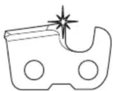
- Keep the correct depth gauge setting. Obey the instructions and use the recommended depth gauge setting.

- Make sure that the saw chain has the correct tension. If the saw chain is not tight against the guide bar, the saw chain can derail. An incorrect saw chain tension increases wear on the guide bar, saw chain and chain drive sprocket. Refer to To tension the chain on page 21.
- Do maintenance on the cutting equipment regularly and keep it correctly lubricated. If the saw chain is not correctly lubricated, the risk of wear on the guide bar, saw chain and chain drive sprocket increases.


Assembly
To assemble the cutting head

CAUTION: Make sure that the drive shaft inside the shaft engages with the cut-out in the cutting head.

- Loosen the screw on the cutting head, (A)
- Fit the cutting head on the shaft so that the screw (A) is aligned with the hole in the shaft as shown.
- Finger tighten the screw (A). Make sure that screw (A) fits into the hole in the shaft.
- Tighten screw (A).
- Tighten screw (B).
To assemble the bar and chain
- Unscrew the bar nut and remove the protective cover.
-
Fit the bar over the bar bolt. Place the bar in its rearmost position. Place the chain over the drive sprocket and in the groove on the bar. Begin on the top side of the bar.
-
Make sure that the edges of the cutting links are facing forward on the top edge of the guide bar.

- Fit the cover and locate the chain adjuster pin (A) in the hole in the bar. Check that the drive links of the chain fit correctly on the drive sprocket (B) and that the chain is in the groove in the bar (C). Tighten the bar nut finger-tight.

- Tension the chain by turning the chain tensioning screw clockwise using the combination spanner. The chain should be tensioned until it does not sag from the underside of the bar.
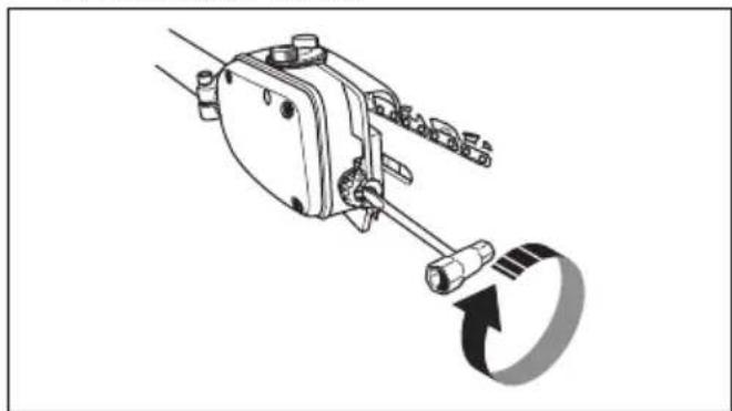
- The chain is correctly tensioned when it does not sag from the underside of the bar, but can still be turned easily by hand. Hold up the bar tip and tighten the bar nuts with the combination spanner.

- When fitting a new chain, the chain tension has to be checked frequently until the chain is run-in. Check the chain tension regularly. A correctly tensioned chain ensures good cutting performance and long life.
To adjust the harness
You should always use the harness with the machine to give maximum control over the machine and reduce the risk of fatigue in your arms and back.
- Put on the harness.
- Hook the machine onto the harness support hook.
- Adjust the length of the harness so that the support hook is roughly level with your right hip.

To assemble the two-piece shaft 525P5S
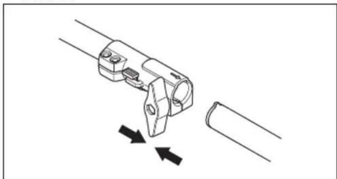
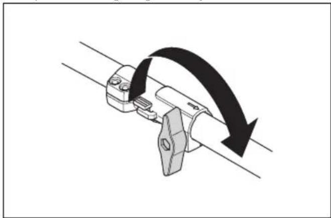
- Turn the knob to loosen the coupling.
- Align the tab of the cutting attachment (A) with the arrow of the coupling (B).

- Carefully push the shaft into the coupling until you hear a click.
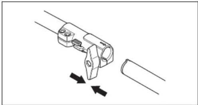
- Tighten the knob fully.

To disassemble the two-piece shaft 525P5S
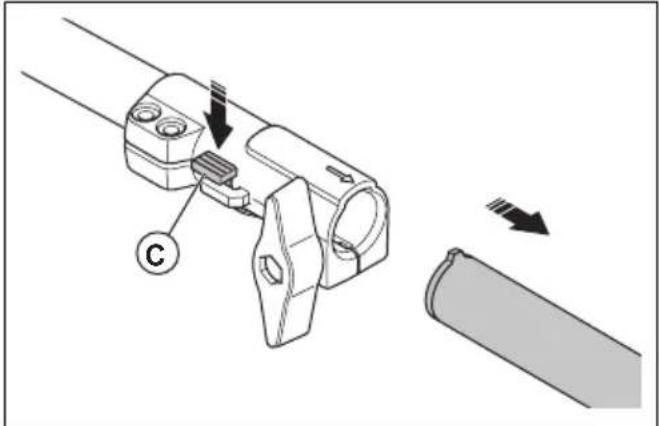
- Turn the knob 3 turns or more to loosen the coupling.

- Push and hold the button (C).
- Hold tight in the end of the shaft that the engine is attached to.
- Pull the attachment straight out of the coupling.

To assemble the impact guard
- Assemble the guard with 3 screws.

- Tighten the screws to 30 ft/lbs (4 Nm).
- Tighten the screws again when the product has been in use for about 20 hours.
Operation
Introduction

WARNING: Before you operate the product, you must read and understand the safety chapter.
To check before starting
- Inspect the working area. Remove any objects that could be thrown out.
- Check the saw chain. Never use blunt, cracked or damaged equipment.
- Check that the product is in perfect working order.
- Check that all nuts and screws are tight.
- Make sure the chain is adequately lubricated, refer to To check the chain lubrication on page 22.
- Check that the saw chain always stops when the engine is idling.
-
Only use the product for the purpose it was intended for.
-
Make sure the handle and safety features are in order. Never use a machine that has any parts missing or has been modified in relation to the specification.
Fuel
This product has a two-stroke engine.

CAUTION: Incorrect type of fuel can result in engine damage. Use a mixture of gasoline and two-stroke oil.
Premixed fuel
- Use Husqvarna premixed alkylate fuel for best performance and extension of the engine life. This fuel contains less harmful chemicals compared to regular fuel, which decreases harmful exhaust fumes. The quantity of remains after combustion is lower with this fuel, which keeps the components of the engine more clean.
To mix fuel
Gasoline

CAUTION: Do not use gasoline with an octane number less than 90 RON (87 AKI). This can cause damage to the product.

CAUTION: Do not use gasoline with more than 10% ethanol concentration (E10). This can cause damage to the product.

CAUTION: Do not use leaded gasoline. This can cause damage to the product.
• Always use new unleaded gasoline with a minimum octane number of 90 RON (87 AKI) and with less than 10% ethanol concentration (E10).
- Use gasoline with a higher octane number if you frequently use the product at continuously high engine speed.
• Always use a good quality unleaded gasoline/oil mixture.
Two-stroke oil
- For best results and performance use Husqvarna two-stroke oil.
- If Husqvarna two-stroke oil is not available, use a two-stroke oil of good quality for air-cooled engines. Speak to your servicing dealer to select the correct oil.

CAUTION: Do not use two-stroke oil for water-cooled outboard engines, also referred to as outboard oil. Do not use oil for four-stroke engines.
To mix gasoline and two-stroke oil
| Gasoline, liter | Two-stroke oil, liter |
| 2% (50:1) | |
| 5 0.10 | |
| 10 0.20 | |
| 15 0.30 | |
| 20 0.40 |

CAUTION: Small errors can influence the ratio of the mixture drastically when you mix small quantities of fuel. Measure the
quantity of oil carefully and make sure that you get the correct mixture.

- Fill half the quantity of gasoline in a clean container for fuel.
- Add the full quantity of oil.
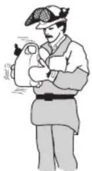
- Shake the fuel mixture.
- Add the remaining quantity of gasoline to the container.
- Carefully shake the fuel mixture.

CAUTION: Do not mix fuel for more than 1 month at a time.
To fill the fuel tank
- Clean the area around the fuel tank cap.
- Shake the container and make sure that the fuel is fully mixed. Use a fuel container with an anti-spill valve.
- Fill the fuel tank.
- Tighten the fuel tank cap carefully.
- Move the product 3 m (10 ft) or more away from the refueling area and fuel source before starting.


CAUTION: Contamination in the tanks causes malfunction. Clean the fuel tank and chain oil tank regularly and replace the fuel filter one time a year or more.
To do a run-in
- During the first 10 hours of operation, do not apply full throttle without load for extended periods.
To use the correct chain oil

WARNING: Do not use waste oil, which can cause injury to you and the environment. Waste oil also causes damage to the oil pump, the guide bar and the saw chain.

WARNING: The saw chain can break if the lubrication of the cutting equipment is not sufficient. Risk of serious injury or death to the operator.

WARNING: This product has a function that lets the fuel run out before the chain oil. Use the correct chain oil for this safety function to operate correctly. Speak to your servicing dealer when you select your chain oil.
Note: This product has an automatic chain lubrication system. You can also adjust the oil flow. Refer to To adjust chain lubrication on page 22.
- Use Husqvarna chain oil for maximum saw chain life and to minimise environmental damage. If Husqvarna chain oil is not available, we recommend you to use a standard chain oil.
- Use a chain oil with good adherence to the saw chain.
- Use a chain oil with correct viscosity range that agrees with the air temperature.

CAUTION: If the oil is too thin, it runs out before the fuel. In temperatures below 0°C/32°F some chain oils become too thick, which can cause damage to the oil pump components.
- Use the recommended cutting equipment. Refer to Accessories on page 25
To use the product
- Hold the product as close to your body as possible to get the best balance. Use the harness to support the weight of the machine and make it easier to handle.
- Make sure that the tip does not touch the ground.
- Do not rush the work, but work steadily until all the branches have been cut back cleanly.
• Always slow the engine to idle speed after each working operation. Long periods at full throttle without any load on the engine can lead to serious engine damage.
• Always work at full throttle.
- Whenever possible position yourself so that you can make the cut at right angles to the branch.

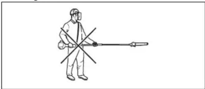
- Do not work with the shaft held straight out in front of you as this increases the apparent weight of the cutting attachment.
- Cut large branches in sections so that you have better control over where they fall.

- Never cut through the swelling at the root of the branch as this will slow down healing and increase the risk of fungal attack.

- Use the stop at the base of the cutting head to provide support during cutting. This will help prevent the cutting attachment from bouncing on the branch.

- Make an initial cut on the underside of the branch before cutting through the branch. This will prevent tearing of the bark, which could lead to slow healing and cause permanent damage to the tree. The cut should not be deeper than 1/3 of the branch thickness to prevent jamming. Keep the chain running while you withdraw the cutting attachment from the branch to prevent it jamming.

To prepare the product for start
- Push the air purge bulb 10 times.

Note: It is not necessary to fully fill the bulb.
- Move the choke control up into choke position.


WARNING: The saw chain will start to rotate immediately when you start the engine with the choke.
To start the product

WARNING: Read the warning instructions in the safety chapter before you start the product (refer to Safety on page 4).
- Use protective gloves.
- Hold the body of the product on the ground with your left hand.

CAUTION: Do not use your feet!
- Hold the starter rope handle with your right hand.
- Slowly pull out the starter rope with your right hand until you feel some resistance (the starter pawls grip).

WARNING: Do not twist the starter rope around your hand.
- Pull the cord quickly and with power.

CAUTION: Do not pull the starter rope all the way out and do not let go off the starter rope handle when the starter rope is fully extended. This can cause damage to the product.
- Pull the starter rope until the engine starts or for a maximum of 5 times.
- Reset the choke when the engine starts or after you pull the starter rope 5 times.
- If it is necessary, pull the starter rope again and again until the engine starts.
- Let the engine run for 10 seconds.
- Operate the throttle gradually.
- Make sure the engine runs smoothly.
Note: If the engine stops, do the procedure again.
About the surface

WARNING: Do not put parts of your body in the grey marked area. If you touch the grey marked area it can result in burns to the skin. It can also cause electrical shock if the spark plug cap has been damaged. Do not use a product with a damaged spark plug cap.

To stop the product
- Move the stop switch into the stop position to stop the engine.


CAUTION: The stop switch automatically goes back to its initial position. In order to prevent accidental starting, the spark plug cap must be removed from the spark plug when assembling, checking and/or maintenance is done.
Maintenance
Introduction
Below you will find some general maintenance instructions. If you need further information please contact your service workshop.
Note: The user must only carry out the maintenance and service work described in this operator's manual. More extensive work must be carried out by an authorized service workshop.
Maintenance schedule
The following is a list of the maintenance steps that must be performed on the product. Most of the items are described later in this chapter.
| Maintenance Daily Weekly Monthly | |||
| Clean the external surface. X | |||
| Make sure that the throttle trigger lock and the throttle works correctly. X | |||
| Do a check of the stop switch to make sure that it works correctly. X | |||
| Make sure that the saw chain does not rotate at idle speed. X | |||
| Clean the air filter. Replace if necessary. X | |||
| Check the saw chain with regard to visible cracks in the rivets and links, whether the saw chain is stiff or whether the rivets and links are abnormally worn. | X | ||
| Clean the area under the protective cover. X | |||
| Make sure that the screws and nuts are tight. X | |||
| Examine the engine, the fuel tank and the fuel lines for leaks. X | |||
| Clean the cooling system. X | |||
| Examine the starter and the starter rope for damages. X | |||
| Examine the vibration damping elements for damages and cracks. X | |||
| Clean the outside of the spark plug. Remove it and do a check of the electrode gap. Adjust the gap to the correct distance (refer to To examine the spark plug on page 17) or replace the spark plug. Make sure that the spark plug is fitted with a suppressor. | X | ||
| Clean the outside of the carburetor and the space around it. X | |||
| File off any burrs from the edges of the bar. X | |||
| Clean or replace the spark arrestor screen on the muffler. X | |||
| Clean the fuel tank. X | |||
| Do a check of the fuel filter for contamination and the fuel hose for cracks or other defects. Replace if necessary. | X | ||
| Do a check of all cables and connections. X | |||
| Do a check of the clutch, clutch springs and the clutch drum for wear. Replace if necessary by an authorized service workshop. | X | ||
| Examine the spark plug. Replace the spark plug if it is necessary. X | |||
| Do an inspection of the dielectric shaft for worn and damaged areas. Do not use the product if the dielectric shaft has worn or damaged areas. Refer to OSHA 1910.269 for more information. | X |
To adjust the idle speed
- Make sure that the air filter is clean and the air filter cover is attached before you adjust the idle speed.
- Start the product. Refer to To start the product on page 14
- Adjust the idle speed with the idle adjustment screw T which is identified with "T" mark. Turn the idle adjustment screw clockwise until the saw chain starts to turn.

- Turn the idle adjustment screw counterclockwise until the saw chain stops.
The idle speed is correct when the engine operates smoothly in all positions. The idle speed must be below the speed when the saw chain starts to turn.

WARNING: If the saw chain does not stop when you adjust the idle speed, turn to your nearest servicing dealer. Do not use the product until it is correctly adjusted or repaired.
Note: Refer to Technical data on page 24 for the recommended idle speed.
To do maintenance on the muffler
The muffler decreases the noise level and directs the exhaust gases away from the operator.

WARNING: Mufflers that have catalytic converters get very hot during operation and will stay hot for some time after you stop the product. This also applies at idle speed. If you touch the product it can result in burns to the skin. Think about of the risk of fire.
-
Stop the product and let it cool down.
-
Remove the cover to the muffler.

- Remove the screw holding the spark arrestor mesh.
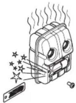
- Clean the spark arrestor mesh if it is blocked or replace it if it is damaged.

CAUTION: The spark arrestor mesh must be replaced if it is damaged. Do not use a product if the spark arrestor mesh on the muffler is missing or defective.

CAUTION: If the spark arrestor mesh is frequently blocked it can be a sign that performance of the catalytic converter is decreased. Turn to your servicing dealer to examine the muffler. A blocked spark arrestor mesh will cause overheating and result in damage to the cylinder and piston.
Cooling system
The product has a cooling system to keep the operation temperature as low as possible.
Clean the components of the cooling system with a brush weekly or more frequently in rougher conditions. A dirty or blocked cooling system makes the product too hot which causes damage to the piston and cylinder.
The cooling system has the following components:
- Air intake on the starter.
- Fins on the flywheel.
- Cooling fins on the cylinder.
- Cylinder cover.
- Muffler cover.
- Muffler plate.

To examine the spark plug

CAUTION: Always use the recommended spark plug type, refer to Technical data on page 24. Incorrect spark plug type can cause damage to the product.
- Examine the spark plug if the engine is low on power, is not easy to start or does not operate correctly at idle speed.
• To decrease the risk of unwanted material on the spark plug electrodes, obey these instructions:
a) Make sure that the idle speed is correctly adjusted.
b) Make sure that the fuel mixture is correct.
c) Make sure that the air filter is clean. - If the spark plug is dirty, clean it and make sure that the electrode gap is correct, refer to Technical data on page 24.

- Replace the spark plug if it is necessary.
Air filter
Remove dust and dirt from the air filter to keep it clean and prevent these problems:
• Carburetor malfunctions.
- Problems when you start the product.
- Loss of engine power.
- Increased wear to engine parts.
• Too much fuel consumption.
To clean the air filter

CAUTION: An air filter that is damaged, very dirty, or soaked with fuel must always be replaced.
Clean the air filter from dirt and dust regularly. This prevents carburetor malfunctions, starting problems, loss of engine power, wear to engine parts and more fuel consumption than usual.
If you use an air filter for a long time, it cannot be fully cleaned. Replace the air filter with a new one at regular intervals. Refer to Maintenance schedule on page 15.
- Move the choke lever up to close the choke valve.

- Remove the air filter cover and the air filters.

-
Clean the air filters with warm soap water.
-
Replace the air filters if they cannot be fully cleaned. Always replace a damaged air filter.
-
Clean the inner surface of the air filter cover. Use compressed air or a brush.
-
Do a check of the rubber seal on the air filter. Replace the air filter if the rubber seal is damaged.
-
Make sure that the air filter is dry before you install it.
Two piece-shaft
Apply grease to the end of the drive shaft after each 30 hours of operation. There is a risk that the drive shaft ends (splined coupling) on models with two-piece shafts will seize if they are not lubricated regularly.

To check the chain drive sprocket
- Regularly check the degree of wear on the drive sprocket. Replace if wear is excessive.

To examine the cutting equipment
- Make sure that there are no cracks in rivets and links and that no rivets are loose. Replace if it is necessary.

-
Make sure that the saw chain is easy to bend. Replace the saw chain if it is rigid.
-
Compare the saw chain with a new saw chain to examine if the rivets and links are worn.
-
Replace the saw chain when the longest part of the cutting tooth is less than 4 mm/0.16 in. Also replace the saw chain if there are cracks on the cutters.

To do a check of the guide bar
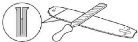
- Make sure that the oil channel is not blocked. Clean if it is necessary.

- Examine if there are burrs on the edges of the guide bar. Remove the burrs using a file.

- Clean the groove in the guide bar.

- Examine the groove in the guide bar for wear. Replace the guide bar if it is necessary.

- Examine if the guide bar tip is rough or very worn.
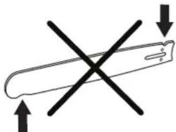
- Make sure that the bar tip sprocket turns freely and that the lubricating hole in the bar tip sprocket is not blocked. Clean and lubricate if it is necessary.

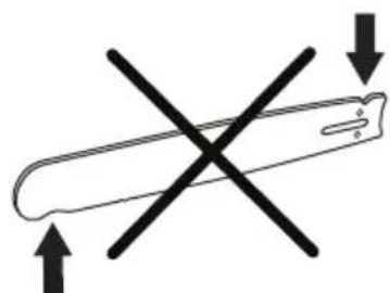
- Turn the guide bar daily to extend its life cycle.

To sharpen the saw chain
Information about the guide bar and saw chain

WARNING: Use protective gloves when you use or do maintenance on the saw chain. A saw chain that does not move can also cause injuries.
Replace a worn or damaged guide bar or saw chain with the guide bar and saw chain combination recommended by Husqvarna. This is necessary to keep the safety functions of the product. Refer to Accessories on page 25, for a list of replacement bar and chain combinations that we recommend.
- Guide bar length, in/cm. Information about the guide bar length can usually be found on the rear end of the guide bar.

• Number of teeth on bar tip sprocket (T).

- Chain pitch, in. The distance between the drive links of the saw chain must align with the distance of the teeth on the bar tip sprocket and drive sprocket.

• Number of drive links. The number of drive links is decided by the type of guide bar.

- Bar groove width, in/mm. The groove width in guide bar must be the same as the chain drive links width.

- Chain oil hole and hole for chain tensioner. The guide bar must align with product.

- Drive link width, mm/in.

General information about how to sharpen the cutters
Do not use a blunt saw chain. If the saw chain is blunt, you must apply more pressure to push the guide bar through the wood. If the saw chain is very blunt, there will be no wood chips but sawdust.
A sharp saw chain eats through the wood and the wood chips becomes long and thick.
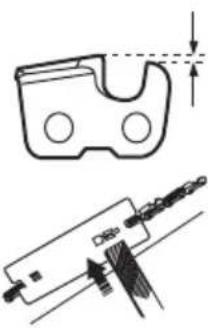
The cutting tooth (A) and the depth gauge (B) together makes the cutting part of the saw chain, the cutter. The
difference in height between the two gives the cutting depth (depth gauge setting).

When you sharpen the cutter, think about the following:
- Filing angle.

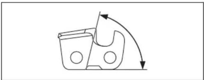
- Cutting angle.
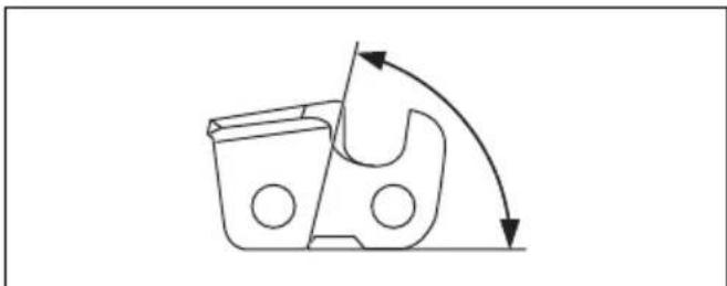
- File position.
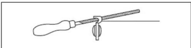
- Round file diameter.

It is not easy to sharpen a saw chain correctly without the correct equipment. Use Husqvarna file gauge. This will help you to keep maximum cutting performance.
Note: Refer to To sharpen the cutters on page 21 for information about sharpening of the saw chain.
To sharpen the cutters
- Use a round file and a file gauge to sharpen the cutting teeth.
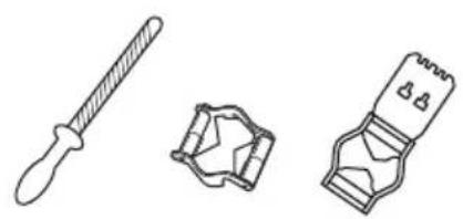
Note: Refer to Filing equipment and filing angles on page 25 for information about which file and gauge that Husqvarna recommends for your saw chain.
- Apply the file gauge correctly on to the cutter. Refer to the instruction supplied with the file gauge.
- Move the file from the inner side of the cutting teeth and out. Decrease the pressure on the pull stroke.

- Remove material from one side of all the cutting teeth.
- Turn the product around and remove material on the other side.
- Make sure that all cutting teeth are the same length.
General information about how to adjust the depth gauge setting
The depth gauge setting (C) decreases when you sharpen the cutting tooth (A). To keep maximum cutting performance you must remove filing material from the depth gauge (B) to receive the recommended depth gauge setting. Refer to Technical data on page 24 for instructions about how to receive the correct depth gauge setting for your saw chain.

To adjust the depth gauge setting
Before you adjust the depth gauge setting or sharpen the cutters, refer to General information about how to sharpen the cutters on page 20, for instructions. We recommend you to adjust the depth gauge setting after each third operation that you sharpen the cutting teeth.
We recommend that you use our depth gauge tool to receive the correct depth gauge setting and bevel for the depth gauge.

- Use a flat file and a depth gauge tool to adjust the depth gauge setting. Only use Husqvarna depth gauge tool to get the correct depth gauge setting and bevel for the depth gauge.
- Put the depth gauge tool on the saw chain.
Note: See the package of the depth gauge tool for more information about how to use the tool.
- Use the flat file to remove the part of the depth gauge that extends through the depth gauge tool.

To tension the chain

WARNING: A saw chain with an incorrect tension can derail from the guide bar and cause serious injury or death.
A saw chain becomes longer when you use it. Adjust the saw chain regularly.
- Loosen the bar nut that hold the clutch cover/chain brake. Use a wrench.

-
Tighten the bar nuts by hand as tightly as you can.
-
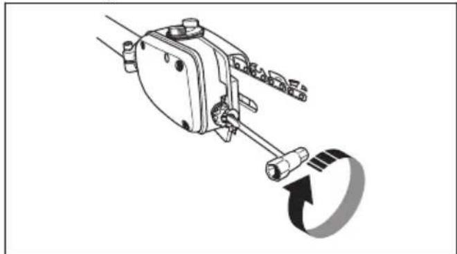
Lift the front of the guide bar and turn the chain tensioning screw. Use a wrench.
-
Tighten the saw chain until it is tight against the guide bar but still can move easily.
-
Tighten the bar nuts using the wrench and lift the front of the guide bar at the same time.

- Make sure you can pull the saw chain around freely by hand and that it does not hang from the guide bar.

To fill with chain oil
- Open the oil cap on top of the bar head.

-
Fill with Husqvarna saw chain oil.
-
Attach the cap again.
To check the chain lubrication
- Check the chain lubrication each time you refuel. Aim the tip of the bar at a light coloured surface about 20 cm (8 inches) away. After 1 minute running at 75 % throttle you should see a distinct line of oil on the light surface.
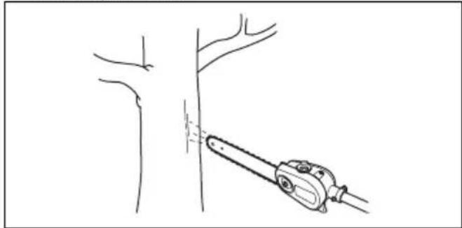
- If the saw chain lubrication does not operate correctly, do a check of the guide bar. Refer to To do a check of the guide bar on page 19 for instructions. Speak to your servicing dealer if the maintenance steps does not help.
To adjust chain lubrication

WARNING: Stop the engine before you make adjustments to the oil pump.
Turn the adjustment screw for the oil pump. Use a screwdriver or combination wrench.
- Turn the adjuster screw clockwise to decrease the oil flow.

- Turn the adjuster screw counterclockwise to increase the oil flow.
Troubleshooting
The engine does not start
| Check Possible cause Procedure | ||
| Stop switch. The stop switch is in the stop position. | stop position. | Let an approved service agent replace the stop switch. |
| Fuel tank. Incorrect fuel type. Drain the fuel tank and fill with cor-rect fuel. | fuel tank and fill with cor-rect fuel. | |
| Spark plug and cylinder. The spark plug is dirty or wet. Make sure that the spark plug is dry and clean. | The spark plug electrode gap is incorrect. | Clean the spark plug. Make sure that the electrode gap is correct, refer to Technical data on page 24. Make sure that the spark plug has a suppressor. |
| The spark plug is loose. Tighten the spark plug. | ||
| Engine is flooded because of repeated starts with full choke after ignition. | Remove and clean the spark plug. Put the product on its side with the spark plug hole away from you. Pull the starter rope handle 6-8 times. Assemble the spark plug and start the product. Refer to To start the product on page 14. | |
The engine starts but stops again
| Check | Possible cause Procedure | |
| Fuel tank Incorrect fuel | type. Empty the fuel tank and fill it with correct | fuel. |
| Air filter The air filter is | clogged. Clean the air filter. |
Transportation, storage and disposal
Transportation and storage
- For storage and transportation of the product and fuel, make sure that there are no leaks or fumes. Sparks or open flames, for example from electrical devices or boilers, can start a fire.
- Always use approved containers for storage and transportation of fuel.
-
Empty the fuel and chain oil tanks before transportation or before long-term storage. Discard the fuel and chain oil at an applicable disposal location.
-
Use the transportation guard on the product to prevent injuries or damage to the product. A saw chain that does not move can also cause serious injuries.
- Remove the spark plug cap from the spark plug.
- Attach the product safely during transportation.
To prepare your product for long-term storage
-
Stop the product and let it become cool before you disassemble it.
-
Disassemble and clean the saw chain and the groove in the guide bar.

CAUTION: If the saw chain and guide bar are not cleaned, they can become rigid or blocked.
- Attach the transportation guard.
- Clean the product. Refer to Maintenance on page 15 for instructions.
- Do a complete servicing of the product.
Technical data
Technical data
| 525P4S 525P5S | ||
| Engine | ||
| Cylinder displacement, cm3 | 25.4 25.4 | |
| Cylinder bore, mm 34 34 | ||
| Stroke, mm 28 28 | ||
| Recommended max. speed, rpm 11000-12000 11000-12000 | ||
| Idle speed, rpm 2800-3000 2800-3000 | ||
| Max. engine output, according to ISO 8893, kW/rpm 1.0/8500 1.0/8500 | ||
| Catalytic converter muffler Yes Yes | ||
| Speed-regulated ignition system Yes Yes | ||
| Ignition system | ||
| Spark plug NGK BPMR8Y NGK BPMR8Y | ||
| Electrode gap, mm | 0.65 0.65 | |
| Fuel and lubrication system | ||
| Fuel tank capacity, litre/cm3 | 0.5/500 | 0.5/500 |
| Oil tank capacity, litre/cm3 | 0.2/200 | 0.2/200 |
| Weight | ||
| Without fuel, cutting attachment and guard, kg | 5.3 | 6.4 |
| Noise emissions1 | ||
| Sound power level, measured according to ISO 22868, dB (A) | 107 | 107 |
| Sound levels2 | ||
| Equivalent sound pressure level at the operator's ear, measured according to ISO 22868, dB(A): | ||
| Equipped with approved accessory (original) | 91 90 | |
| Vibration levels3 | ||
| Equivalent vibration levels ( ahv,eq ) at handles, measured according to ISO 22867, m/s 2 : | ||
| Equipped with approved accessory (original), front/rear 3.6/3.5 3.6/3.5 | ||
Accessories
Guidebar and saw chain combinations
Recommended guide bar and saw chain combination.
| Guide bar Saw chain | ||||
| Length, in/cm Pitch, in Gauge, in/mm Type Length, drive links, no. | ||||
| 10/25 | 3/8 0.050/1.3 Husqvarna H37 | 40 | ||
| 12/31 45 | ||||
| 10/25 | 3/8 0.050/1.3 Husqvarna S93G | 40 | ||
| 12/31 45 | ||||
Filing equipment and filing angles
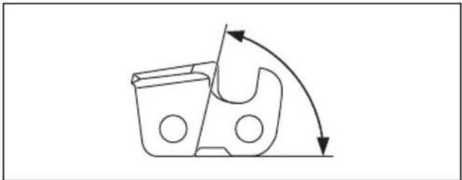
Using Husqvarna file gauge will give you the correct filing angles. We recommend you to always use a Husqvarna file gauge to restore the sharpness of the
saw chain. The part numbers are given in the table below.
If you do not know which saw chain you have on your product, turn to your servicing dealer.
 |  |  |  |  |  |
 | |||||
| H37 5/32 in | / 4.0 mm 80° 30° | 0.025 in / 0.65 mm | 580 24 37-01 | ||
| S93G 5/32 in | / 4.0 mm 60° 30° | 0.025 in / 0.65 mm | 587 80 90-01 |
EC Declaration of Conformity
EC Declaration of Conformity
Husqvarna AB, SE-561 82 Huskvarna, Sweden, tel: +46-36-146500, declares that the pole saws Husqvarna 525P4S and 525P5S with serial numbers dating from 2016 onwards (the year is clearly stated on the rating plate, followed by the serial number), comply with the requirements of the COUNCIL'S DIRECTIVE:
• of May 17, 2006 "relating to machinery" 2006/42/EC
• of February 26, 2014 "relating to electromagnetic compatibility" 2014/30/EU
- of June 8, 2011 "on the restriction of the use of certain hazardous substances in electrical and electronic equipment" 2011/65/EU
The following standards have been applied:
EN ISO 12100:2010, EN ISO 11680-1:2011, ISO 14982:2009, CISPR 12:2009, EN 50581:2012.
RISE SMP Svensk Maskinprovning AB, Box 7035, SE-750 07 Uppsala, Sweden, has carried out EC type examination in accordance with the machinery directive's (2006/42/EC) article 12, point 3b. The certificate for EC type examination in accordance with annex IV, has the number: 0404/15/2438
In addition, 0404, RISE SMP Svensk Maskinprovning AB, Box 7035, SE-750 07 Uppsala, Sweden, has certified conformity with annex V of the Council's Directive of May 8, 2000 "relating to the noise emissions in the environment" 2000/14/EC.
Huskvarna, 2016-03-30

Pär Martinsson, Development Manager (Authorized representative for Husqvarna AB and responsible for technical documentation.)
Inhalt
Montage


- Schnittwinkel.

- Schärfposition.

Montage
Pour assembler la protection antichocs

AVERTISSEMENT: La scie

• L'angle d'impact.
• La position de la lime.

Rotatierichting, zaagketting.

Trillingsdempingssysteem controleren
Montage
De zaagkop monteren


Deelbare steel demonteren 525P5S
De stootbescherming monteren

Product stoppen

Bougie controleren

• Vervang de bougie indien nodig.
Luchtfilter
Snijuitrusting controleren
Zaagketting slijpen
- Snijhoek.
• Vijlpositie.

De ketting spannen

- Nosite trpežno obutev, ki ne drsi.
Preverjanje sistema za dušenje tresljajev
- Elemente sistema za dušenje tresljajev morate pravilno namestiti.
Preverjanje dušilnika

• Vizualno preverite lovilec isker.

Montaža
- Verigo napnite tako, da vijak napenjalca verige s kombiniranim ključem obrnete v smeri vrtenja urinih kazalcev. Verigo je treba toliko napeti, da na spodnji strani meča ni povešena.

- Po namestitvi nove verige je treba napetost verige redno preverjati, dokler se ta ne uteče. Redno preverjajte napetost verige. Pravilno napeta veriga nudi dobro učinkovitost rezanja in dolgo življenjsko dobo.
Nastavitev oprtnika
- Previdno potisnite gred v spojko, da se slišno zaskoči.
- Popolnoma zategnite gumbni vijak.
Razstavljanje dvodelne gredi 525P5S
- Pritisnite in pridržite gumb (C).
- Trdno držite konec gredi, na katero je pritrjen motor.
- Priključek izvlecite naravnost iz spojke.
- Vijake zategnite z momentom 30 ft/lbs (4 Nm).
- Po približno 20 urah uporabe izdelka vijake znova zategnite.
Delovanje
Uvod

OPOZORILO: Pred uporabo izdelka morate prebrati in razumeti poglavje o varnosti.
Pregled pred vžigom

- Dolijte polovico bencina v čisto posodo za gorivo.
- Dodajte celotno količino olja.
- Pretresite mešanico goriva.
- V posodo dodajte še preostalo količino bencina.
- Temeljito pretresite mešanico goriva.

To prepare the product for start
- Push the air purge bulb 10 times.

Opomba: It is not necessary to fully fill the bulb.
- Move the choke control up into choke position.


OPOZORILO: The saw chain will start to rotate immediately when you start the engine with the choke.
Zagon izdelka


- Vijak za prilagajanje v prostem teku obračajte v nasprotni smeri urinega kazalca, dokler se veriga ne ustavi.
- Odstranite vijak, s katerim je pritrjen lovilnik isker.

Pregled svečke

- Odstranite pokrov zračnega filtra in zračne filtre.

-
Prepričajte se, da je verigo mogoče preprosto zviti. Če je veriga toga, jo zamenjajte.
-
Verigo primerjajte z novo verigo, da ugotovite, će so kovice in členi obrabljeni.
-
Zamenjajte verigo, ko je najdaljši del rezalnega zoba krajši od 4 mm/0,16 palca. Verigo prav tako zamenjajte, će so na rezilih razpoke.

Preverjanje meča
- Prepričajte se, da oljni kanal ni zamašen. Po potrebi ga očistite.

- Preglejte, ali so na robovih meča grobi ostanki. S pilo odstranite grobe ostanke.
- Očistite utor v meču.

- Preverite, ali je utor v meču obrabljen. Po potrebi zamenjajte meč.

- Preverite, ali je konica meča groba ali zelo obrabljena.
Brušenje verige
- Širina gonilnega člena v mm/palcih.

Splošne informacije o brušenju rezil
- Kot rezanja.

- Položaj pile.

- Premer okrogle pile.

Napenjanje verige

-
Izdelek Husqvarna napolnite z verižnim oljem.
-
Znova namestite pokrovček.
Kontrola mazanja verige
- Za povečanje pretoka olja zavrtite nastavitveni vijak v nasprotni smeri vrtenja urinega kazalca.
Odpravljanje težav
Original instructions
Originalanweisungen


- INTRODUCTION
- INTENDED USE
- PRODUCT OVERVIEW
- SYMBOLS ON THE PRODUCT
- PRODUCT LIABILITY
- SAFETY
- SAFETY DEFINITIONS
- GENERAL SAFETY INSTRUCTIONS
- SAFETY INSTRUCTIONS FOR ASSEMBLY
- SAFETY INSTRUCTIONS FOR OPERATION
- PERSONAL PROTECTIVE EQUIPMENT
- SAFETY DEVICES ON THE PRODUCT
- TO DO A CHECK OF THE THROTTLE TRIGGER LOCKOUT
- FUEL SAFETY
- SAFETY INSTRUCTIONS FOR MAINTENANCE
- SAFETY INSTRUCTIONS FOR THE CUTTING EQUIPMENT
- ASSEMBLY
- TO ASSEMBLE THE CUTTING HEAD
- TO ASSEMBLE THE BAR AND CHAIN
- TO ADJUST THE HARNESS
- TO ASSEMBLE THE TWO-PIECE SHAFT 525P5S
- TO DISASSEMBLE THE TWO-PIECE SHAFT 525P5S
- TO ASSEMBLE THE IMPACT GUARD
- OPERATION
- TO CHECK BEFORE STARTING
- FUEL
- PREMIXED FUEL
- TO MIX FUEL
- TO FILL THE FUEL TANK
- TO DO A RUN-IN
- TO USE THE CORRECT CHAIN OIL
- TO USE THE PRODUCT
- TO PREPARE THE PRODUCT FOR START
- TO START THE PRODUCT
- ABOUT THE SURFACE
- TO STOP THE PRODUCT
- MAINTENANCE
- MAINTENANCE SCHEDULE
- TO ADJUST THE IDLE SPEED
- TO DO MAINTENANCE ON THE MUFFLER
- COOLING SYSTEM
- TO EXAMINE THE SPARK PLUG
- AIR FILTER
- TO CLEAN THE AIR FILTER
- TWO PIECE-SHAFT
- TO CHECK THE CHAIN DRIVE SPROCKET
- TO EXAMINE THE CUTTING EQUIPMENT
- TO DO A CHECK OF THE GUIDE BAR
- TO SHARPEN THE SAW CHAIN
- GENERAL INFORMATION ABOUT HOW TO SHARPEN THE CUTTERS
- TO SHARPEN THE CUTTERS
- GENERAL INFORMATION ABOUT HOW TO ADJUST THE DEPTH GAUGE SETTING
- TO ADJUST THE DEPTH GAUGE SETTING
- TO TENSION THE CHAIN
- TO FILL WITH CHAIN OIL
- TO CHECK THE CHAIN LUBRICATION
- TO ADJUST CHAIN LUBRICATION
- TROUBLESHOOTING
- TRANSPORTATION, STORAGE AND DISPOSAL
- TRANSPORTATION AND STORAGE
- TO PREPARE YOUR PRODUCT FOR LONG-TERM STORAGE
- TECHNICAL DATA
- ACCESSORIES
- GUIDEBAR AND SAW CHAIN COMBINATIONS
- FILING EQUIPMENT AND FILING ANGLES
- EC DECLARATION OF CONFORMITY
- INHALT
- MONTAGE
- POUR ASSEMBLER LA PROTECTION ANTICHOCS
- TRILLINGSDEMPINGSSYSTEEM CONTROLEREN
- DE ZAAGKOP MONTEREN
- DEELBARE STEEL DEMONTEREN 525P5S
- DE STOOTBESCHERMING MONTEREN
- PRODUCT STOPPEN
- BOUGIE CONTROLEREN
- LUCHTFILTER
- SNIJUITRUSTING CONTROLEREN
- ZAAGKETTING SLIJPEN
- DE KETTING SPANNEN
- PREVERJANJE SISTEMA ZA DUŠENJE TRESLJAJEV
- MONTAŽA
- NASTAVITEV OPRTNIKA
- RAZSTAVLJANJE DVODELNE GREDI 525P5S
- DELOVANJE
- UVOD
- PREGLED PRED VŽIGOM
- ZAGON IZDELKA
- PREGLED SVEČKE
- PREVERJANJE MEČA
- BRUŠENJE VERIGE
- SPLOŠNE INFORMACIJE O BRUŠENJU REZIL
- NAPENJANJE VERIGE
- KONTROLA MAZANJA VERIGE
- ODPRAVLJANJE TEŽAV
Brand : HUSQVARNA
Model : 525P4S
Category : Saw