531RS - Brush cutter HUSQVARNA - Free user manual and instructions
Find the device manual for free 531RS HUSQVARNA in PDF.
| Type de produit | Petrol brushcutter |
| Marque | Husqvarna |
| Modèle | 531RS |
| Cylindrée | 33.6 cm³ |
| Poids (sans carburant) | 6.9 kg |
| Capacité du réservoir de carburant | 0.74 L |
| Régime de ralenti | 2,500 ± 200 rpm |
| Régime maximal recommandé | 12,000 rpm |
| Régime de l'arbre de sortie | 8,570 rpm |
| Puissance moteur max. | 1.2 kW / 1.6 hp at 7,000 rpm |
| Bougie d'allumage | NGK BPMR 7A |
| Écartement des électrodes | 0.6 - 0.7 mm |
| Niveau de puissance sonore garanti | 108 dB(A) |
| Pression sonore à l'oreille (tête de désherbage) | 90 dB(A) |
| Pression sonore à l'oreille (lame à herbe) | 89 dB(A) |
| Vibrations poignée G/D (tête de désherbage) | 2.8 / 3.0 m/s² |
| Vibrations poignée G/D (lame à herbe) | 4.2 / 4.0 m/s² |
| Alimentation | Mixture of 2-stroke gasoline and oil (50:1) |
| Équipement de coupe | Weed head T35/T35X, Multi blades (255-330 mm), Tricut plastic blades |
| Entretien filtre à air | Every 25 hours |
| Distance de sécurité | 15 m |
Frequently Asked Questions - 531RS HUSQVARNA
User questions about 531RS HUSQVARNA
0 question about this device. Answer the ones you know or ask your own.
Ask a new question about this device
Download the instructions for your Brush cutter in PDF format for free! Find your manual 531RS - HUSQVARNA and take your electronic device back in hand. On this page are published all the documents necessary for the use of your device. 531RS by HUSQVARNA.
USER MANUAL 531RS HUSQVARNA
natural_image
Silhouette of a selfie stick with a head-mounted device (no text or symbols)531RS, 541RS, 541RST
EAC
EN Operator's manual 2-26
Transportation and storage....23
Technical data....23
Accessories.... 24
EC Declaration of Conformity.... 26
Introduction
Product description
This product is a brushcutter with a combustion engine.
Work is constantly in progress to increase your safety and efficiency during operation. Speak to your servicing dealer for more information.
product for other tasks than grass trimming and grass clearing. Use a grass blade or trimmer head to cut grass.
Note: National or local regulations may regulate the use. Comply to given regulations.
Intended use
The product can be used with a grass blade or a trimmer head to cut different types of vegetation. Do not use the
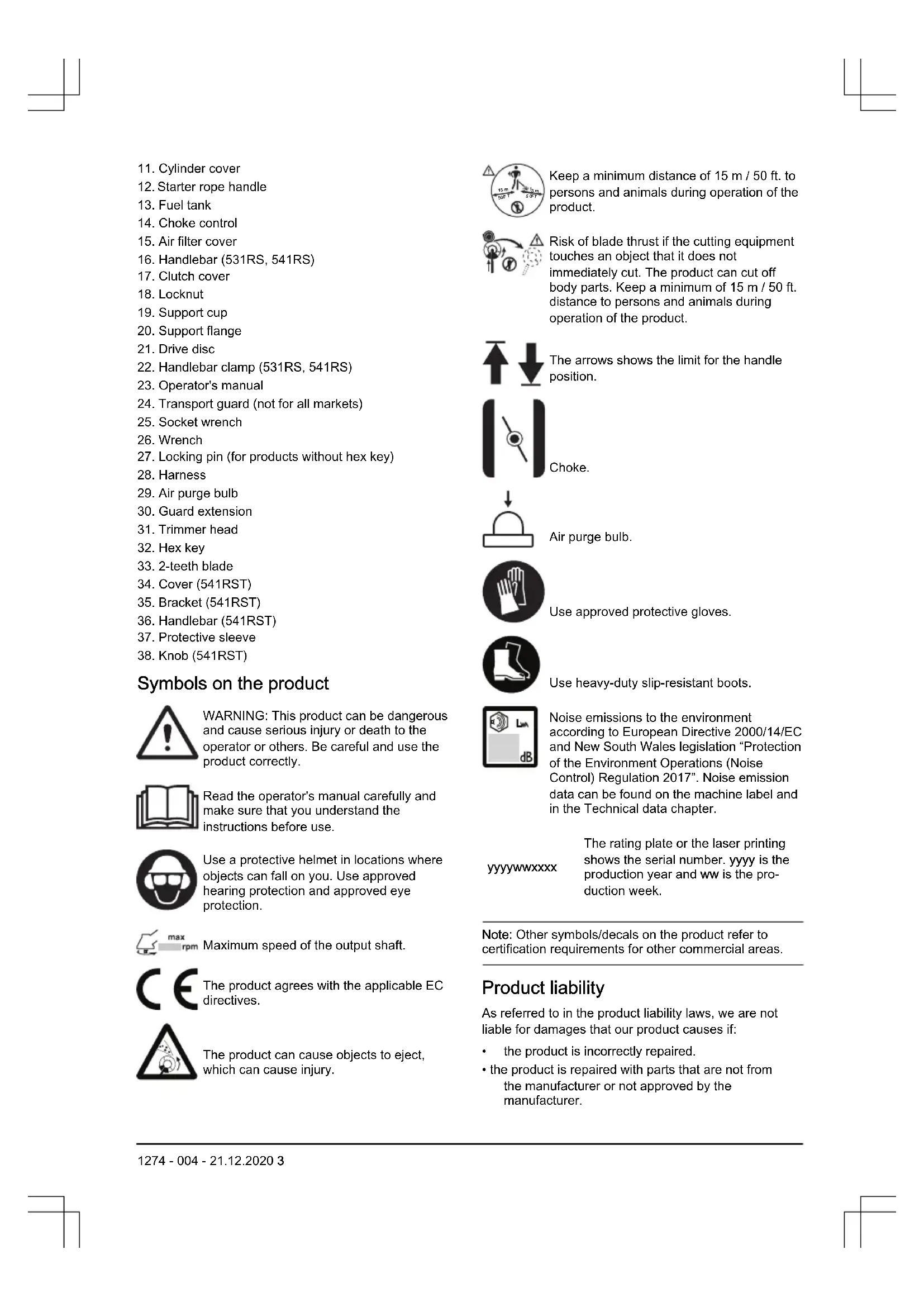
Product overview
-
Blade (not for all markets)
-
Grease filler cap, bevel gear
-
Bevel gear
-
Cutting attachment guard
-
Shaft
-
Start throttle button
-
Stop switch
-
Throttle control
-
Throttle lockout
-
Suspension ring
-
Cylinder cover
-
Starter rope handle
-
Fuel tank
-
Choke control
-
Air filter cover
-
Handlebar (531RS, 541RS)
-
Clutch cover
-
Locknut
-
Support cup
-
Support flange
-
Drive disc
-
Handlebar clamp (531RS, 541RS)
-
Operator's manual
-
Transport guard (not for all markets)
-
Socket wrench
-
Wrench
-
Locking pin (for products without hex key)
-
Harness
-
Air purge bulb
-
Guard extension
-
Trimmer head
-
Hex key
-
2-teeth blade
-
Cover (541RST)
-
Bracket (541RST)
-
Handlebar (541RST)
-
Protective sleeve
-
Knob (541RST)
Symbols on the product

WARNING: This product can be dangerous and cause serious injury or death to the operator or others. Be careful and use the product correctly.

Read the operator's manual carefully and make sure that you understand the instructions before use.

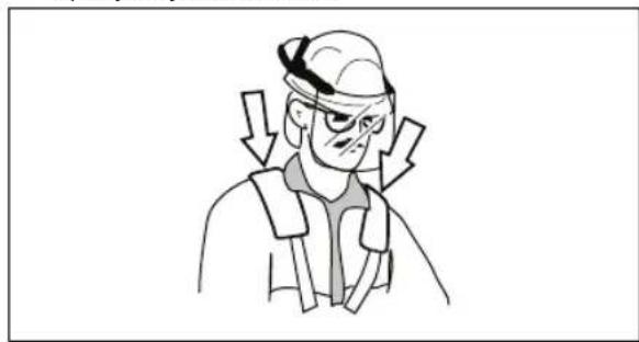
Use a protective helmet in locations where objects can fall on you. Use approved hearing protection and approved eye protection.

Maximum speed of the output shaft.

The product agrees with the applicable EC directives.
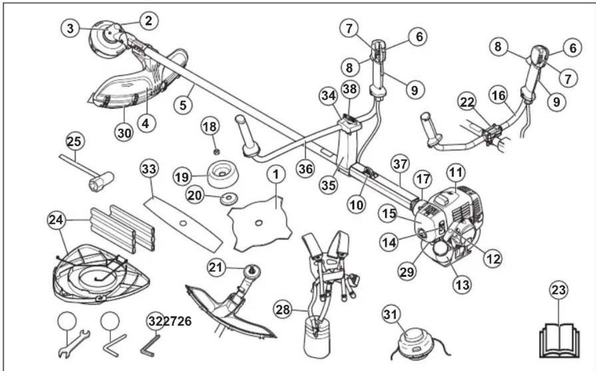
The product can cause objects to eject, which can cause injury.
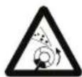
Keep a minimum distance of 15 m / 50 ft. to persons and animals during operation of the product.
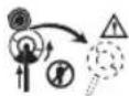
Risk of blade thrust if the cutting equipment touches an object that it does not immediately cut. The product can cut off body parts. Keep a minimum of 15 m / 50 ft. distance to persons and animals during operation of the product.

The arrows shows the limit for the handle position.

Choke.
Air purge bulb.

Use approved protective gloves.

Use heavy-duty slip-resistant boots.
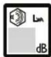
Noise emissions to the environment according to European Directive 2000/14/EC and New South Wales legislation "Protection of the Environment Operations (Noise Control) Regulation 2017". Noise emission data can be found on the machine label and in the Technical data chapter.
yyyyMMddxxxx
The rating plate or the laser printing shows the serial number. yyyy is the production year and ww is the production week.
Note: Other symbols/decals on the product refer to certification requirements for other commercial areas.
Product liability
As referred to in the product liability laws, we are not liable for damages that our product causes if:
• the product is incorrectly repaired.
- the product is repaired with parts that are not from the manufacturer or not approved by the manufacturer.
- the product has an accessory that is not from the manufacturer or not approved by the manufacturer.
- the product is not repaired at an approved service center or by an approved authority.
Safety
Safety definitions
The definitions below give the level of severity for each signal word.

WARNING: Injury to persons.

CAUTION: Damage to the product.
Note: This information makes the product easier to use.
General safety instructions

WARNING: Read the warning instructions that follow before you use the product.
- Use the product correctly. Injury or death is a possible result of incorrect use. Only use the product for the tasks found in this manual. Do not use the product for other tasks.
- Obey the instructions in this manual. Obey the safety symbols and the safety instructions. If the operator does not obey the instructions and the symbols, injury, damage or death is a possible result.
- Do not discard this manual. Use the instructions to assemble, to operate and to keep your product in good condition. Use the instructions for correct installation of attachments and accessories. Only use approved attachments and accessories.
- Do not use a damaged product. Obey the maintenance schedule. Only do the maintenance work that you find an instruction about in this manual. An approved service center must do all other maintenance work.
- This manual cannot include all situations that can occur when you use the product. Be careful and use your common sense. Do not operate the product or do maintenance on the product if you are not sure about of the situation. Speak to a product expert, your dealer, service agent or approved service center for information.
- Disconnect the spark plug cable before you assemble the product, put the product into storage or do maintenance.
- Do not use the product if it is changed from its initial specification. Do not change a part of the product without approval from the manufacturer. Only use
parts approved by the manufacturer. Injury or death is a possible result of incorrect maintenance.
- Do not breathe in the fumes from the engine. Long-term inhalation of the engine's exhaust fumes is a health risk.
- Do not start the product indoors or near flammable material. The exhaust fumes are hot and can contain a spark which can start a fire. Not sufficient airflow can cause injury or death because of asphyxiation or carbon monoxide.
- When you use this product the engine makes an electromagnetic field. The electromagnetic field can cause damage to medical implants. Speak to your physician and medical implant manufacturer before you operate the product.
- Do not let a child operate the product. Do not let a person without knowledge of the instructions operate the product.
- Make sure that you always monitor a person, with decreased physical capacity or mental capacity, that uses the product. A responsible adult must be there at all times.
- Lock the product in an area that children and unapproved persons cannot access.
- The product can eject objects and cause injuries. Obey the safety instructions to decrease the risk of injury or death.
- Do not go away from the product when the engine is on.
- The operator of the product is responsible if an accident occurs.
- Make sure that parts are not damaged before you use the product.
- Make sure that you are at minimum 15 m (50 ft) away from other persons or animals before you use the product. Make sure that persons in the adjacent area know that you will use the product.
- Refer to national or local laws. They can prevent or decrease the operation of the product in some conditions.
- Do not use the product if you are fatigued or influenced by alcohol, drugs or medicine. They can have effects on your vision, alertness, coordination or judgment.
Safety instructions for assembly

WARNING: Read the warning instructions that follow before you use the product.
- Use approved protective gloves when you assemble the product and cutting attachment.
- Remove the spark plug cap from the spark plug before you assemble the product.
- Make sure that the correct handlebar and cutting attachment guard are assembled before you operate the product.
- A defective or incorrect cutting attachment guard can cause injury. Do not use a cutting attachment without an approved cutting attachment guard.
- Attach the clutch cover and shaft correctly before you start the product.
- The drive disc and support flange must engage correctly in the center hole of the cutting attachment. A cutting attachment that is attached incorrectly can cause injury or death.
- Attach the harness to the product to prevent injury to the operator or others.
Safety instructions for operation
- Make sure the product is fully assembled before you use it.
- Before a start, move the product 3 m (10 ft) away from the position where you filled the fuel tank. Put the product on a flat surface. Make sure that the cutting attachment does not touch the ground or other objects.
- The product can cause objects to eject, which can cause damage to the eyes. Always use an approved eye protection when you operate the product.
- Be careful, a child can come near the product without your knowledge during operation.
- Do not operate the product if there are persons in the work area. Stop the product if a person goes into the work area.
- Make sure that you are always in control of the product.
- Do not use the product if you cannot receive aid if an accident occurs. Always make sure others know you will operate the product before you start to operate the product.
- Do not turn with the product before you make sure that no persons or animals are in the safety area.
- Remove all unwanted materials from the work area before you start. If the cutting attachment hits an object, the object can eject and cause injury or damage. Unwanted material can wind around the cutting attachment and cause damage.
- Do not use the product in bad weather (fog, rain, strong winds, risk of lightning or other weather conditions.). Dangerous conditions (such as slippery surfaces) can occur because of bad weather.
- Make sure that you can move freely and work in a stable position.

natural_image
Illustration of a person using a long-handled tool to dig or brush outdoors, with a tree nearby (no text or symbols)- Make sure that you cannot fall when you use the product. Do not tilt when you operate the product.
• Always hold the product with your two hands. Hold the product on the right side of your body.
natural_image
Line drawing of a person in full protective suit holding a long tool, no text or symbols present- Operate the product with the cutting attachment below your waist.
- If the choke control is in the choke position when the engine starts, the cutting attachment starts to turn.
- Do not touch the bevel gear after the engine stops. The bevel gear is hot after the engine stops. Hot areas can cause injury.
- Stop the engine before you move the product.
- Do not put down the product with the engine on.
- Before you remove the unwanted materials from the product, stop the engine and wait until the cutting attachment stops. Let the cutting attachment stop before you or an aid remove the cut material.
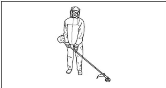
Personal protective equipment

WARNING: Read the warning instructions that follow before you use the product.
• Always use correct personal protective equipment when you operate the product. The personal protective equipment does not erase the risk of injury. The personal protective equipment decreases the grade of injury if an accident occurs.
• Always use an approved eye protection while you operate the product.
- Do not operate the product with bare feet or with open shoes. Always use heavy-duty slip-resistant boots.
- Use heavy, long pants.
- If it is necessary, use approved protective gloves.
- Use a helmet if it is possible that objects fall on your head.
• Always use approved ear protection while you operate the product. Noise for a long period can cause noise-induced hearing loss.
• Make sure that you have a first aid kit near.
Protective devices on the product
• Make sure that you regularly do the maintenance to the product.
• The life of the product increases.
• The risk of accidents decreases.
Let an approved dealer or an approved service center regularly examine the product to do adjustments or repairs.
- Do not use a product with damaged protective equipment. If the product is damaged, speak to an approved service center.
To do a check of the throttle trigger lockout
- Make sure that the throttle trigger lockout (A) and throttle trigger (B) move freely and that the return spring operates correctly.
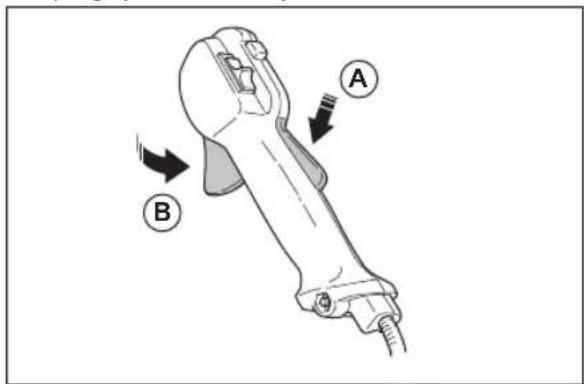
- Push down the throttle trigger lockout and make sure that it goes back to its initial position when you release it.
natural_image
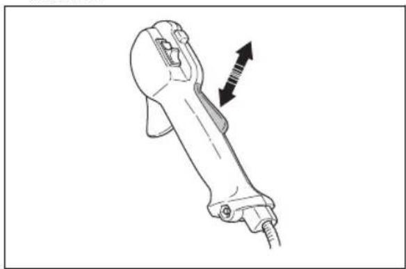
Line drawing of a robotic arm with an arrow indicating motion or force direction (no text or symbols)- Make sure that the throttle trigger is locked at the idle position when the throttle trigger lockout is released.
natural_image
Line drawing of a robotic arm with a directional arrow indicating motion (no text or symbols)- Start the product and apply full throttle.
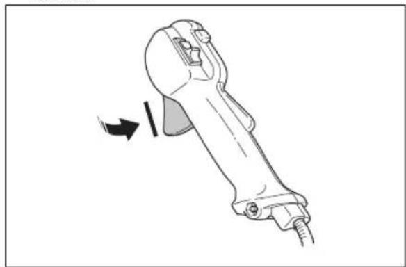
- Release the throttle trigger and make sure that the cutting attachment stops and stays stationary.

WARNING: If the cutting attachment moves when the throttle trigger is in the idle position, then the carburetor idle speed must be adjusted. Refer to To adjust the idle speed on page 20.
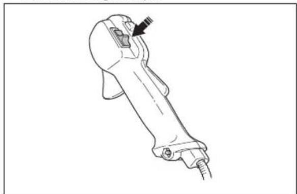
To do a check of the stop switch
- Start the engine.
- Move the stop switch to the stop position and make sure that the engine stops.
natural_image
Line drawing of a mechanical device with a handle and screw base (no text or symbols)To do a check of the cutting attachment guard
The cutting attachment guard prevents injuries and stops objects that eject in the direction of the operator.
-
Stop the engine.
-
Do a visual check for damages, for example cracks.
natural_image
Technical line drawing of a mechanical assembly with no visible text or symbols- Replace the cutting attachment guard if it is damaged.
To do a check of the vibration damping system
The vibration damping system decreases vibration in the handles to a minimum which makes the operation easier.
natural_image
Technical line drawing of a mechanical device with no visible text or symbols-
Stop the engine.
-
Do a visual check for deformation and damage, for example cracks.
-
Make sure that the elements of the vibration damping system are attached correctly.
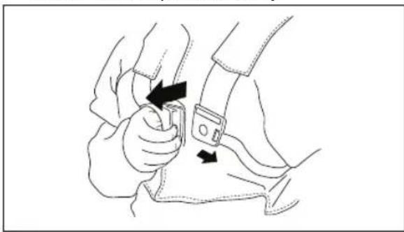
To do a check of the quick-release mechanism

WARNING: Do not use a harness with a defective quick-release mechanism.
The quick-release mechanism lets the operator remove the product quickly from the harness if there is an emergency.
-
Stop the engine.
-
Do a visual check for damage, for example cracks.
-
Release and attach the quick-release mechanism to make sure that it operates correctly.
natural_image
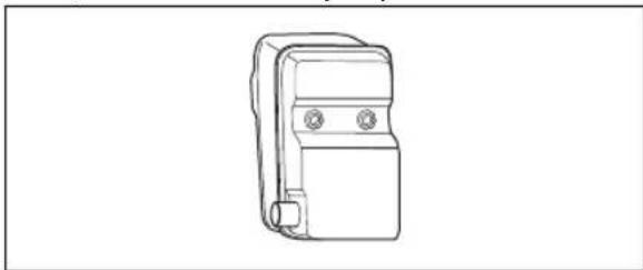
Line drawing of a person adjusting a belt buckle, showing two hands and a belt buckle (no text or symbols)To do a check of the muffler

WARNING: Never use a product with a faulty muffler.


WARNING: Bear in mind that the exhaust fumes from the engine are hot and may contain sparks which can start a fire. Never start the product indoors or near combustible material!
The muffler keeps noise levels to a minimum and sends exhaust fumes away from the operator. For mufflers it is very important that you follow the instructions on how to check, maintain and service your product.
natural_image
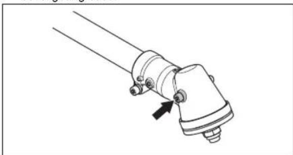
Line drawing of a mechanical device with two circular ports and a handle (no text or symbols)Regularly check that the muffler is securely attached to the product.
natural_image
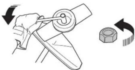
Line drawing of a mechanical switch or lever device (no text or symbols)To attach and remove the locknut

WARNING: Stop the engine, use protective gloves and be careful around the sharp edges of the cutting attachment.
A locknut is used to attach some types of cutting attachments. The locknut has a left thread.
• To attach, tighten the locknut in the opposite direction to the direction of turning of the cutting attachment.
• To remove the locknut, loosen the locknut in the same direction as the cutting attachment rotates.
- To loosen and tighten the locknut, use a socket wrench with a long shaft. The arrow in the picture shows the area where you can operate the socket wrench.
natural_image
Illustration of a hand turning a mechanical component with a nut, showing rotational motion (no text or symbols)
WARNING: When you loosen and tighten the locknut, there is a risk of injury from the blade. You must always make sure that the blade guard prevents injury to your hand when you do this.
Note: Make sure that you can not turn the locknut by hand. Replace the nut if the nylon lining does not have a resistance of a minimum of 1.5 Nm. The locknut must be replaced after it has been put on approximately 10 times.
Cutting equipment
Choose and maintain the cutting equipment to:
- Obtain maximum cutting performance.
- Increase life span of the cutting equipment.
- Follow the checking, maintenance and service instructions for the muffler.
• Always use the recommended guard for the cutting equipment. See Technical data.

WARNING: Only use cutting attachments with the guards we recommend! See the chapter on Technical data. Refer to the instructions for the cutting attachment to check the correct way to load the trimmer line and the correct trimmer line diameter.

WARNING: A faulty cutting attachment may increase the risk of accidents.

WARNING: Always stop the engine before doing any work on the cutting attachment. This continues to rotate even after the throttle has been released. Ensure that the cutting attachment has stopped completely and disconnect the spark plug cap before you start to work on it.
Cutting equipment
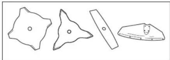
• Use the blades and grass knives to cut thick grass.
natural_image
Four abstract geometric shapes with varying line styles and fill patterns (no text or symbols)- Use the trimmer head to cut grass.
natural_image
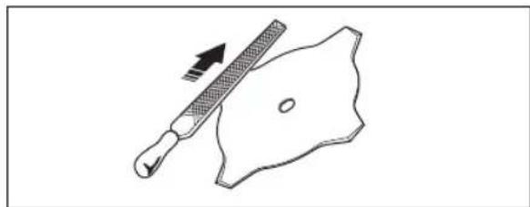
Two technical line drawings of mechanical components: a circular component with a curved handle and a flat plate with a pointed tip (no text or symbols)- An incorrectly sharpened or damaged blade increases the risk of accidents. Keep the teeth of the blade correctly sharpened. Follow the instructions in Maintenance on page 18 and use the recommended file gauge.
natural_image
Simple line drawing of a tool and a shield shape (no text or symbols)- Examine the cutting attachment for damage and cracks. Replace the damaged cutting attachment.
- Only use cutting attachments with recommended cutting attachment guards. Refer to Accessories on page 24.
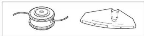
Trimmer head

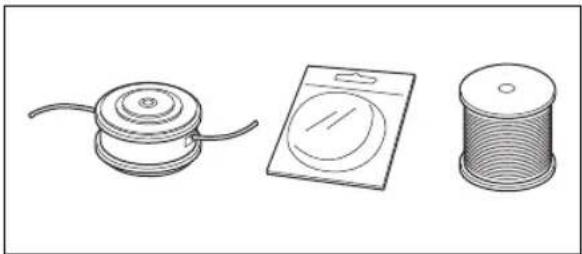
WARNING: Always make sure that the trimmer line is wound tightly and equally around the drum to prevent harmful vibration.
natural_image
Three technical illustrations of mechanical components: a cylindrical component with a coiled cable, a flat plate with a circular cutout, and a spool (no text or symbols)- Only use recommended cutting attachments.
- The length of the trimmer line is important. For a longer trimmer line, more engine power is necessary than for a shorter trimmer line of the same diameter.
- Do not move the installation position of the trimmer guard.
- Make sure that the cutter on the trimmer guard is not damaged. The cutter cuts the trimmer line to the correct length.
- Soak the trimmer line for 2 days before use, to increase its life length.
Grass blades and grass cutters
- Use the product with an approved grass blade. Do not use a grass blade without proper installation of all required parts. Make sure that the installation is done correctly and that the proper parts are used. Improper installation may cause the blade to fly off and seriously injure the operator or the bystanders.
- Wear protective gloves when you handle or do maintenance on the blade.
- Use head protection when you operate a product with a grass blade.
- Grass blades and grass cutters are used to cut rough grass.
- A grass blade can cause injury while it continues to spin after the engine is stopped or the throttle trigger is released. Make sure that the grass blade has completely stopped rotating before any maintenance.
- Stop the engine before you do work on the cutting attachment. Make sure the cutting attachment fully stops. Disconnect the lead from the spark plug.
- Only use an approved cutting attachment or a correctly sharpened blade.
- Keep the teeth of the blade correctly sharpened.
- Do not use a damaged cutting attachment.
- Attach the transport guard to the grass blade when you transport or store the product.
Blade thrust
- A blade thrust is a sudden movement of the product to the side, forward or rearward. A blade thrust occurs when the grass blade hits an object that cannot be cut. In areas where it is not easy to see the material being cut the risk of blade thrust increases.
- When a blade thrust occurs, there is a risk that the product or the operator moves out of position. A blade that moves can hit bystanders and there is a risk of injuries.
- If a blade is bent, has cracks, is broken or damaged, discard the blade.
- Use a sharp blade. The risk of blade thrust increases when a blade is not sharp.
Fuel safety
- Do not start the product if there is fuel or engine oil on the product. Remove the unwanted fuel/oil and let the product dry. Remove unwanted fuel from the product.
- If you spill fuel on your clothing, change clothing immediately.
- Do not get fuel on your body, it can cause injury. If you get fuel on your body, use a soap and water to remove the fuel.
- Do not start the engine if you spill oil or fuel on the product or on your body.
- Do not start the product if the engine has a leak. Examine the engine for leaks regularly.
- Be careful with fuel. Fuel is flammable and the fumes are explosive and can cause injuries or death.
- Do not breathe in the fuel fumes, it can cause injury. Make sure that there is a sufficient airflow.
- Do not smoke near the fuel or the engine.
- Do not put warm objects near the fuel or the engine.
- Do not add the fuel when the engine is on.
• Make sure that the engine is cool before you refuel. - Before you refuel, open the fuel tank cap slowly and release the pressure carefully.
- Do not add fuel to the engine in an indoor area. Not sufficient airflow can cause injury or death because of asphyxiation or carbon monoxide.
- Tighten the fuel tank cap carefully or a fire can occur.
- Move the product at a minimum of 3 m (10 ft) from the position where you filled the tank before a start.
- Do not put too much fuel in the fuel tank.
• Make sure that a leak cannot occur when you move the product or fuel container. - Do not put the product or a fuel container where there is an open flame, spark or pilot light. Make sure that the storage area does not contain an open flame.
- Only use approved containers when you move the fuel or put the fuel into storage.
- Empty the fuel tank before long-term storage. Obey the local law on where to dispose fuel.
- Clean the product before long-term storage.
- Remove the spark plug cable before you put the product into storage to make sure that the engine does not start accidentally.
Safety instructions for maintenance
- If you cannot adjust the idle speed to make the cutting attachment stop, speak to your service center. Do not use the product until the product is correctly adjusted or repaired.
Assembly

WARNING: Read the safety chapter before you assemble the product.
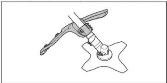
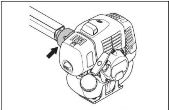
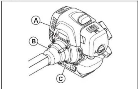
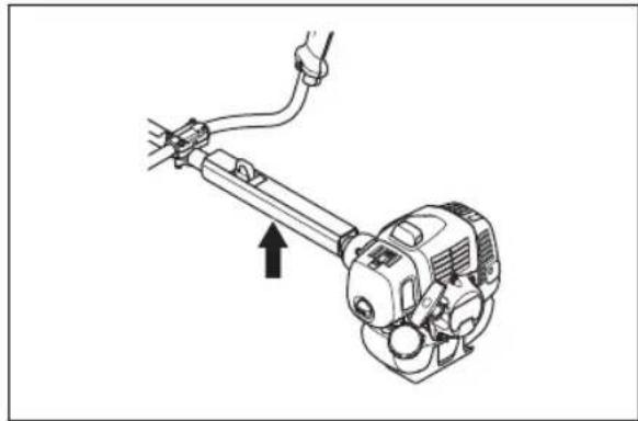
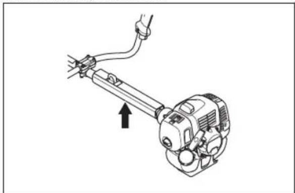
To install the body of the product
- Attach the engine (A) to the tube (B) with 4 screws (C).
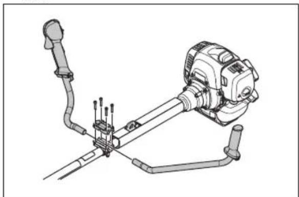
To install the handlebar(531RS, 541RS)
- Install the handlebar in the handlebar clamp on the shaft.
natural_image
Technical line drawing of a mechanical device with articulated arms and a central shaft (no text or symbols)- Install the protective sleeve.
natural_image
Technical line drawing of a manual tool with a mounted device and cable, showing no text or symbols.To install the handlebar (541RST)
- Remove the screw behind the throttle handle.

natural_image
Line drawing of a mechanical tool with a downward arrow indicating motion (no text or symbols)-
Install the throttle handle to the right handlebar.
-
Align the hole behind the throttle handle with the hole in the handlebar.
-
Put the screw through the holes. Tighten the screw.
-
Put the handlebar assembly and the square nut into the bracket. Make sure that the handlebar is in the correct position.
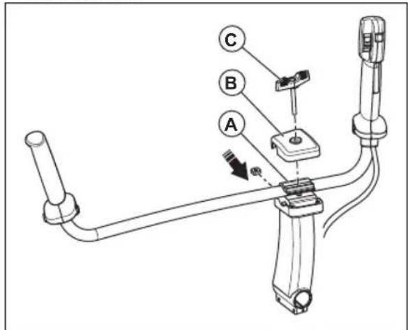
- Install the handlebar clamp (A), cover (B) and knob (C).
- Align the holes for the knob screw.
- Tighten the knob to lock the handlebar tightly.
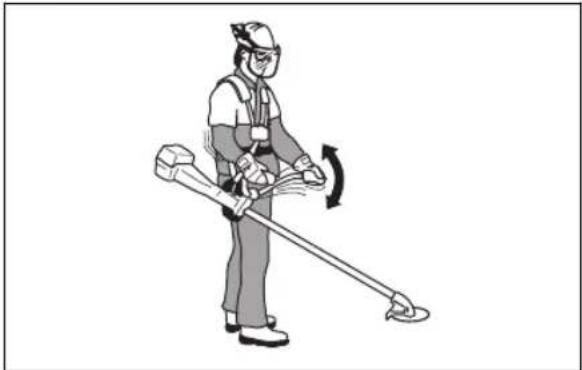
To install the harness
- Put on the harness and hang the product from the suspension point.
- Adjust the handle to put the product in a good work position.
natural_image
Illustration of a person using a handheld tool to clean or walk (no text or symbols present)- Tighten the screws fully.
To connect the throttle cable and stop switch wires
-
Remove the air filter cover.
-
Install the throttle cable (A) through the carburetor bracket (B).
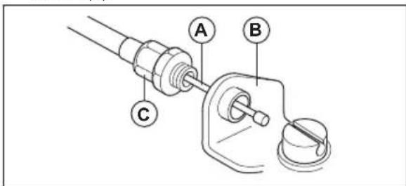
- Turn the cable adjuster sleeve (C) into the carburetor bracket fully.
- Put the slot fitting (D) on the carburetor. At this time, the recessed hole (E) for the cable lug (F) is away from the cable adjuster sleeve (C).

- Rotate the carburetor throttle cam and move the throttle cable (A) through the slot in the slot fitting.
- Make sure the cable lug (F) drops into the recessed hole.
- Operate the throttle trigger some times to make sure that it operates correctly.
- Adjust the cable adjuster sleeve (C).
a) Make sure the stop on the carburetor throttle cam touches the throttle stop correctly.
b) Make sure the cable position keeps 1-2 mm between cable lug (F) and slot fitting when the throttle trigger is fully released.
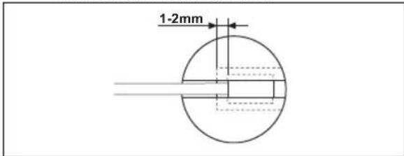
-
When the throttle cable (A) is adjusted correctly, tighten the locknut (G).
-
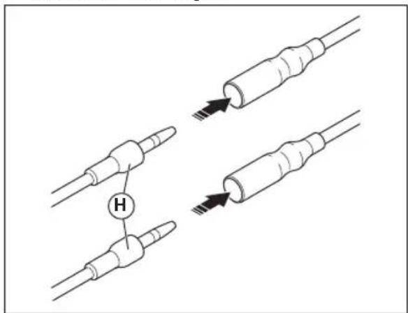
Connect the stop switch wires (H) with the connectors from the engine.
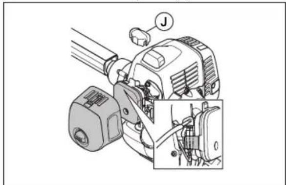
- Install the dust cover (J).
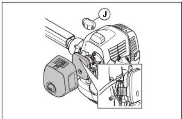
natural_image
Mechanical assembly diagram showing a motor with labeled joint (J) and close-up detail of internal components (no text or symbols)- Install the air filter cover.
To install blades and trimmer heads

WARNING: Only use the approved guard for the blades. See Accessories on page 24. A defective guard can cause injury.

WARNING: If you operate the product with a grass blade, first install the correct handlebar, blade guard and harness.

WARNING: If you do not install the the blades correctly, it can cause injury.
-
Make sure that the lifted section on the drive disc/support flange engages correctly in the center hole of the blades.
-
Install the blades.
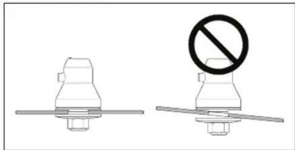
natural_image
Two technical diagrams showing a mechanical component with a prohibition symbol (no text or labels present)To attach and remove the guard extension
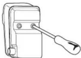
The guard extension is used on the cutting attachment guard. Attach the guard extension when you use a trimmer head or plastic blades. Remove the extension guard when you use a grass blade.
- Put the guide on the guard extension into the slot on the cutting attachment guard. Lock the 4 locking hooks into position.
natural_image
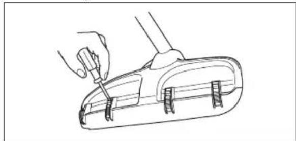
Line drawing of a hand holding a tool, with no text or symbols present- Release the locking hooks with a screwdriver to remove the guard extension.
natural_image
Line drawing of a hand using a screwdriver to adjust or install a small mechanical component (no text or symbols)To attach a blade guard, grass blade and grass cutter

CAUTION: Make sure that the guard extension is removed.
Note: Use the recommended blade guard. Refer to Accessories on page 24.
- Install the blade guard to the shaft. Attach the blade guard with the bolt (L).
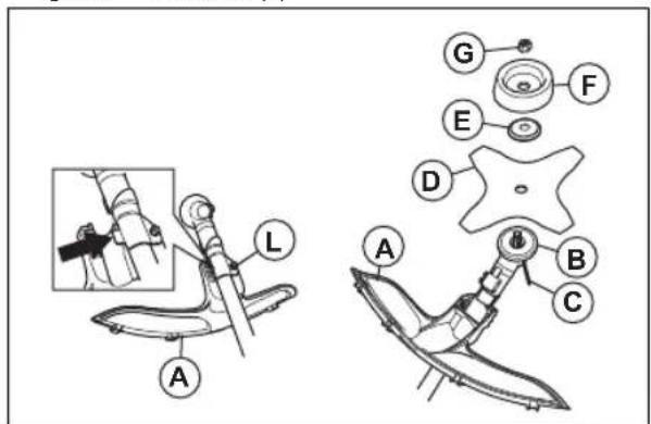
- Attach the drive disc (B) to the output shaft.
- Turn the output shaft until 1 of the holes in the drive disc aligns with the hole in the gear housing.
- Put the locking pin or hex key (C) into the hole to lock the shaft.
- Put the blade (D), support flange (E) and support cup (F) on the output shaft.
- Install the nut (G). Use the combination wrench and tighten the nut to torque 35-50 Nm. Hold the shaft of the combination wrench as near the blade guard as possible.
- To tighten the nut, turn the combination wrench in the opposite direction to the direction of rotation.
natural_image
Technical line drawing of a mechanical component with a curved arrow indicating rotation (no text or symbols)Note: Left hand thread.
To attach the trimmer guard and the trimmer head
Note: Make sure to use the correct trimmer guard for the correct trimmer head.
- Attach the correct trimmer guard/combination guard (A) for the trimmer head.
-
Hang the trimmer guard/combination guard (A) on the 2 hooks on the plate holder (M).
-
Install the trimmer guard/combination guard around the shaft and tighten it with the bolt (L). Use the locking pin or hex key (C).
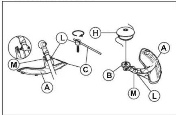
- Put the locking pin or hex key (C) in the groove on the screw head and tighten.
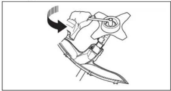
- Attach the drive disc (B) on the output shaft.
- Turn the output shaft until one of the holes in the drive disc aligns with the hole in the gear housing.
- Install the locking pin or hex key (C) in the hole to lock the shaft.
natural_image
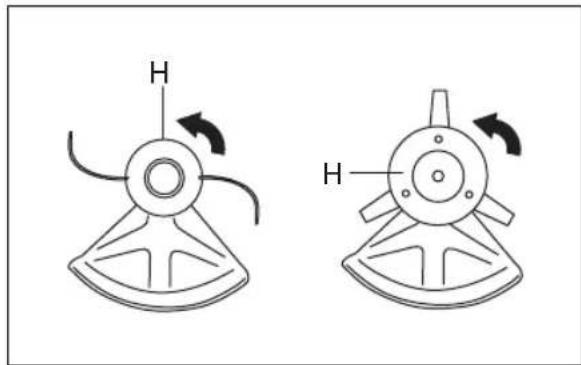
Two mechanical diagrams showing a fan or impeller with rotational arrows, no text or symbols present.- Assemble the trimmer head/plastic blades (H). Turn the trimmer head/plastic blades counterclockwise.
- To disassemble, follow the instructions in the opposite sequence.
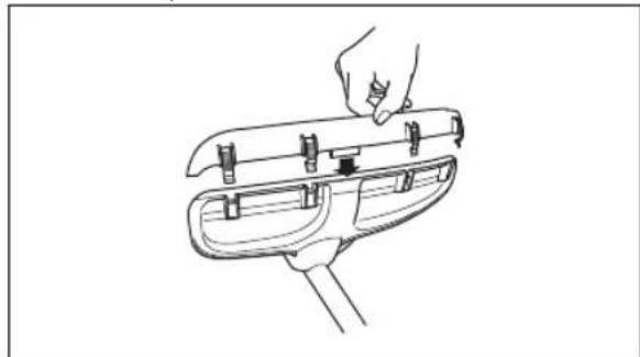
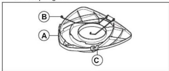
To install the transport guard
- Install the blade in the transport guard (A).
- Put the two fasteners (B) into the slots (C) to attach the transport guard.
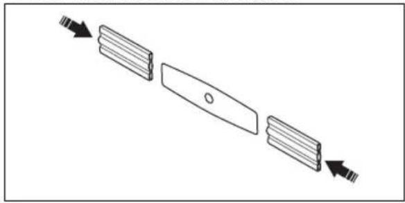
To install the 2-teeth blade in the guard
- Install the blade in the transport guard.
natural_image
Diagram showing three parallel plates with arrows indicating direction, no text or symbols presentTo adjust the harness

WARNING: The product must always be correctly attached to the harness. Do not use a defective harness.
- Put on the harness.
- Connect the product to the harness.
-
Adjust the harness for the best work position.
-
Adjust the side straps to make the product weigh equally on your shoulders.
natural_image
Line drawing of a person wearing a helmet with downward arrows indicating downward motion (no text or symbols)- Adjust the harness until the cutting attachment is parallel to the ground.
- Let the cutting attachment lightly touch the ground. Adjust the harness clamp to balance the product correctly.
Note: If you use a grass blade, it must balance approximately 10 cm /4 in above the ground.
Operation

WARNING: Read and understand the safety chapter before you operate the product.
Fuel
To use fuel

CAUTION: This product has a two-cycle engine. Use a mixture of gasoline and two-cycle engine oil. Make sure to use the correct quantity of oil in the mixture. Incorrect ratio of gasoline and oil can cause damage to the engine.
Gasoline

CAUTION: Do not use gasoline with an octane number less than 90 RON (87 AKI). This can cause damage to the product.

CAUTION: Do not use gasoline with more than 10% ethanol concentration (E10). This can cause damage to the product.

CAUTION: Do not use leaded gasoline. This can cause damage to the product.
• Always use new unleaded gasoline with a minimum octane number of 90 RON (87 AKI) and with less than 10% ethanol concentration (E10).
- Use gasoline with a higher octane number if you frequently use the product at continuously high engine speed.
• Always use a good quality unleaded gasoline/oil mixture.
Two-cycle engine oil
- Use only the two-cycle engine oil of high quality, especially HUSQVARNA two-cycle oil. Use only the oil of an air cooled engine.
• Mixture ratio 50:1 (2%). - Oil of low quality and high oil/fuel ratio can decrease the lifetime of catalytic converters.
- Speak to your dealer when you select an oil.
- If Husqvarna two-stroke oil is not available, you can use another two-stroke oil of good quality that is intended for air cooled engines. Contact your dealer when you select oil.
- Do not use the two-stroke oil for water-cooled outboard engines. The two-stroke oil is sometimes referred to as outboard oil.
| Gasoline, liter Oil, liter | |
| 2%(50:1) | |
| 5 0,1 | |
| 10 0,2 | |
| 15 0,3 | |
| 20 0,4 |
To make the fuel mixture
Note: Always use a clean fuel container when you mix the fuel.
Note: Do not make more than 30 days quantity of fuel mixture.
- Add half of the gasoline quantity.
- Add the full quantity of oil.
- Shake the fuel mixture to mix the contents.
- Add the remaining gasoline quantity.
- Shake the fuel mixture to mix the contents.
- Fill the fuel tank.
To add fuel

WARNING: Do not smoke or put hot objects near fuel. Before you add fuel, stop the engine and let it cool for minutes.

WARNING: When you add fuel, open the fuel tank cap slowly to release unwanted pressure.

WARNING: After you add fuel, tighten the fuel tank cap carefully. Move the machine away from the refuelling area and the power before you start the engine.
• Always use a fuel container with an anti-spill valve.
• Make sure that the area near the fuel tank cap is clean. Contamination in the tank can cause operating problems.
- Shake the fuel container before you add the fuel mixture to the fuel tank.
To start and stop
To examine before start
- Examine the product for missing, damaged, loose or worn parts.
- Examine the nuts, screws and bolts.
- Examine the blades.
- Examine the locknut. Make sure that the locknut has a minimum locking force of 1.5 Nm (1,1 ft lb). Torque the locknut to 35-50 Nm (26-36 ft lb).
-
Examine the air filter.
-
Examine the throttle trigger lockout and the throttle control.
- Examine the stop switch.
- Examine the product for fuel leaks.
To start a cold engine

WARNING: Before you start the product, install the complete clutch cover and shaft. A loose clutch can cause injury. Use gloves.

WARNING: Move the product away from the refuelling area and the fuel source. Put it on a flat surface. Make sure that no objects touch the cutting attachment.

WARNING: Make sure that no unauthorised persons are in the work area. Or it can cause a risk of dangerous injury. The safety distance is 15 m.
- Put the stop switch to the start position.
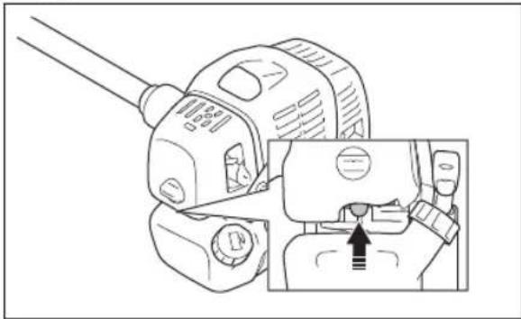
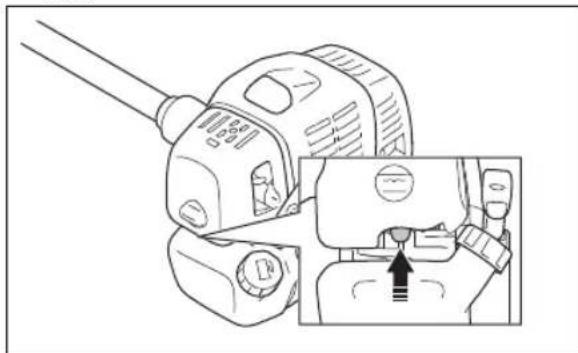
- Push the air purge bulb until fuel starts to fill the bulb.
natural_image
Technical line drawing of a mechanical device with a close-up inset showing a component detail (no text or symbols)- Move the choke control to the choke position.
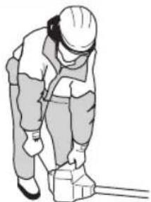
- Hold the product to the ground. Pull out the starter rope slowly with your right hand until you feel some resistance.
natural_image
Illustration of a worker in safety gear handling equipment (no text or symbols)Note: Do not twist the starter rope around your hand

CAUTION: Do not pull the starter rope to full extension. Hold the starter rope handle when it is fully extended. Failure to obey these instructions can cause damage to the engine.
-
Pull the starter rope quickly and with force until you hear that the engine starts.
-
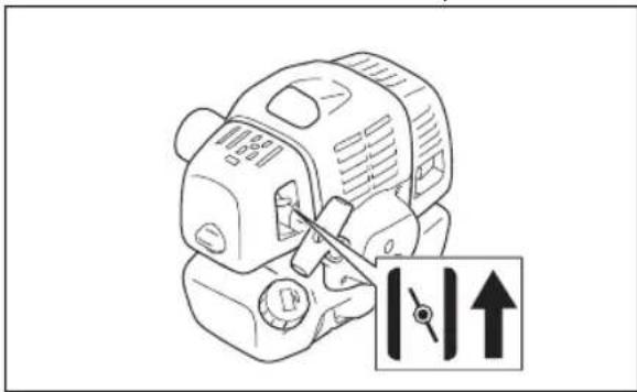
Set the choke control to the run position.

WARNING: Do not touch the cover. It can burn your skin and cause electrical shock if the spark plug cap is damaged. Do not use a product with damaged spark plug cap.
To start a warm engine
-
Put the stop switch to the start position.
-
Push the air purge bulb until fuel starts to fill the bulb.
natural_image
Technical line drawing of a mechanical device with a close-up inset showing a component detail (no text or symbols)- Set the choke control to the run position, then pull the start rope until the engine starts.
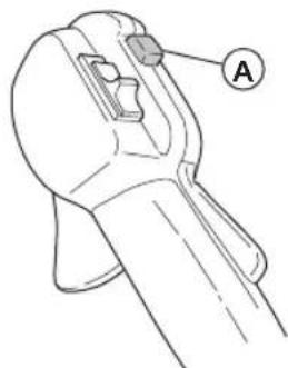
To start with a throttle handle with a start throttle lock
-
Push the throttle lockout and the throttle trigger to set the throttle to the start position. Then push the start throttle button (A).
-
Release the throttle lockout and the throttle trigger, followed by the start throttle button. The throttle function is now activated.
- To return the engine to idle speed, push the throttle lockout and throttle trigger again.
natural_image
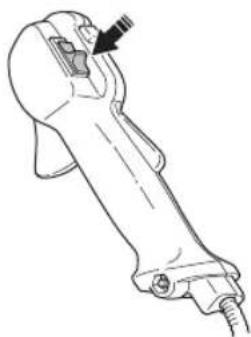
Line drawing of a mechanical device with labeled component A (no text or symbols beyond label)To stop the engine
- Push the throttle trigger to the idle position.
- Move the stop switch to the stop position.
natural_image
Line drawing of a mechanical device with a handle and lever (no text or symbols)To operate the grass trimmer

CAUTION: Make sure that you slow the engine to idle speed after each operation. A long period at full throttle without a load on the engine can cause damage to the engine.
Note: Clean the cover of the trimmer head when you attach a new trimmer line to prevent vibrations. Examine other parts of the trimmer head and clean if it is necessary.
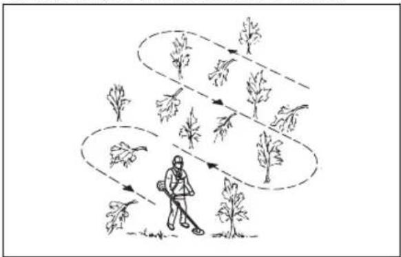
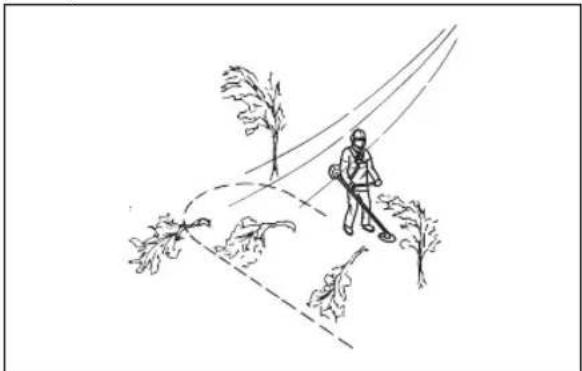
General work instructions

WARNING: Be careful when you cut a tree that is in tension. It can spring back to its normal position before or after the cut and hit you or the product, and cause injury.
- Clear an open space at one end of the work area, and start the work from there.
- Move in a regular pattern across the work area.
flowchart
graph TD
    A["Start"] --> B{Plant Survival}
    B -->|Yes| C["Plant Release"]
    B -->|No| D["Plant Retention"]
    C --> E["Plant Growth"]
    D --> F["Plant Steady"]
    E --> G["Final Plant Status"]
    F --> G
- Move the product fully to the left and right, to clear a width of 4–5 m (13-16 ft) on each turn.
- Clear a length of 75 m (250 ft) before you turn and go back. Move the fuel can along with you as you continue.
- Move in a direction where you do not go across ditches and obstacles more than necessary.
- Move in a direction where the wind makes the cut vegetation fall in the cleared area.
natural_image
Line drawing of a person walking on a path with trees and a curved road (no text or symbols)- Move along slopes, not up and down.
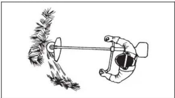
To clear grass with a grass blade
- Keep your feet apart during operation of the product. Make sure feet are tightly against the ground.
- Put the support cup lightly on the ground. This prevents the blade from touching the ground.
- Use a sideway movement from right to left for a clear stroke. Use the left side of the blade (between 8 and 12 o'clock) to cut.
natural_image
Illustration of a hand using a tool to measure a pine branch with a measuring rod (no text or symbols)- Angle the blade to the left when you clear grass.
Note: The grass collects easily in a line.
- Use a sideway movement from left to right for the return stroke.
- Do the work rhythmically.
- Move forward and keep feet tightly against the ground.
- Stop the engine.
- Remove the product from the clip on the harness.
- Put the product on the ground.
- Collect the cut material.
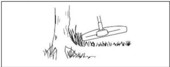
To clear
natural_image
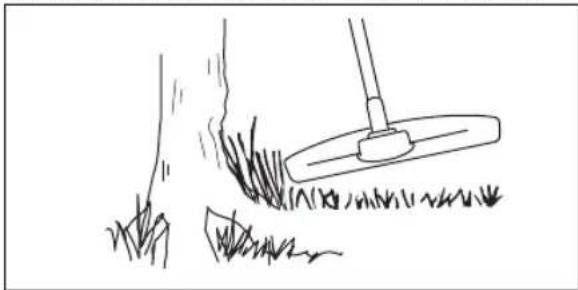
Simple line drawing of a grassy field with a small utility pole and a tool, no text or symbols present.To achieve the best results:
- Hold the trimmer so that the trimmer head is just above the ground.
- Tilt the trimmer head at a slight angle.
- Let the end of the trimmer line strike the ground around objects
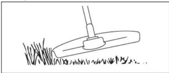
To trim the grass
- Hold the trimmer head immediately above the ground at an angle. Do not push the trimmer line into the grass.
natural_image
Simple line drawing of a grassy field with a small tool or scraper (no text or symbols)- Decrease the length of the trimmer line by 10-12 cm / 4-4.75 in.
- Decrease the engine speed to decrease the risk of damage to plants.
- Use 80 % throttle when you cut grass near objects.
natural_image
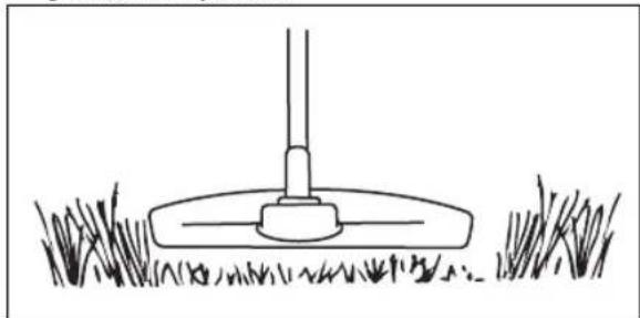
Simple line drawing of a grassy field with a tool and a small object, no text or symbols present.To cut the grass
- Make sure that the trimmer line is parallel to the ground when you cut.
natural_image
Simple line drawing of a grassy field with a small mechanical component at the base (no text or symbols)- Do not push the trimmer head to the ground. The ground and the product can be damaged.
- Do not let the trimmer head touch the ground continuously, it can cause damage to the trimmer head.
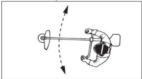
- Use full throttle when you move the product from side to side to cut grass.
natural_image
Diagram of a hand operating a mechanical lever with directional arrows indicating motion (no text or symbols)To sweep the grass
The airflow from the rotating trimmer line can be used to remove cut grass from an area.
- Hold the trimmer head and its trimmer line parallel to the ground and above the ground.
- Apply full throttle.
- Move the trimmer head from side to side and sweep the grass.

WARNING: Clean the trimmer head cover each time you assemble new trimmer line to prevent unbalance and vibrations in the handles. Also do a check of the other parts of the trimmer head and clean it if necessary.
To replace trimmer line
Refer to the last page of this operator's manual.
Maintenance

WARNING: Read and understand the safety chapter before you clean, repair or do maintenance on the product.
Maintenance schedule
| Maintenance Daily Weekly Monthly | |||
| Clean the external surface. X | |||
| Examine the harness for damages. X | |||
| Do a check of the throttle and the throttle trigger. X | |||
| Make sure that the cutting attachment does not rotate at idle speed. X | |||
| Do a check of the stop switch. Refer to To do a check of the stop switch on page 6. | X | ||
| Examine the cutting attachment guard for damages and cracks. X | |||
| Make sure that the grass blade is aligned with the center. Make sure that the grass blade is sharp and that the blade or center hole is not damaged. | X | ||
| Examine the trimmer head for damages and cracks. Replace if it is damaged. X | |||
| Examine the handle and handlebar for damage and make sure that they are attached correctly. | X | ||
| For cutting attachments with a support cup, tighten the locking screw correctly. X | |||
| For cutting attachments with a locknut, tighten the locknut correctly. X | |||
| Examine the transport guard for damage and make sure that it can be attached correctly. | X | ||
| Examine the engine, the fuel tank and the fuel lines for leaks. X | |||
| Clean the air filter. Replace if it is necessary. X | |||
| Tighten nuts and screws. X | |||
| Examine the fuel filter for contamination and the fuel hose for cracks and other defects. Replace if it is necessary. | X | ||
| Examine all cables and connections. X | |||
| Examine the starter and the starter rope for damages. X | |||
| Examine the spark plug. Refer to To examine the spark plug on page 22. | X | ||
| Make sure that the bevel gear is filled to 3⁄4 with grease. X | |||
| Clean the external surface of the carburetor and the area around it. X | |||
| Clean the spark plug. Remove the spark plug and do a check of the electrode gap. Adjust the electrode gap or replace the spark plug if it is necessary. Refer to Technical data on page 23. Make sure that the spark plug is assembled with a suppressor. | X | ||
| Examine the clutch, clutch springs and the clutch drum for wear. Replace if it is necessary. | X | ||
| Replace the spark plug. Make sure that the spark plug is assembled with a suppressor. | X | ||
| Lubricate the drive shaft. X | |||
| Make sure that the vibration damping units are not damaged. X | |||
| Clean the cooling system of the product. | X | ||
| Clean the muffler. | X |
To adjust the carburetor
The basic carburetor settings are adjusted during testing at the factory. Adjustment must be carried out by a trained technician.
To do a check of the muffler

WARNING: Do not use a product that has a defective muffler. Always replace a defective muffler.

WARNING: Risk of burn or fire. Mufflers with catalytic converters get very hot during operation.

WARNING: Risk of fire. The muffler decreases the noise level and identifies the exhaust gases from the operator. The exhaust gases are hot and can contain sparks.

CAUTION: The spark arrester screen must be replaced if it is damaged. Do not use a
product if the spark arrester screen on the muffler is missing or defective.

CAUTION: If the spark arrester screen is blocked, the product will be too hot. This will cause damage to the cylinder and piston.
- Make sure that the muffler is not damaged.
- Make sure that the muffler is correctly attached to the product.
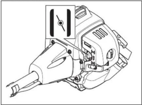
To adjust the idle speed
Your Husqvarna product is made to specifications that decrease harmful emissions.
- Make sure that the air filter is clean and the air filter cover is attached before you adjust the idle speed.
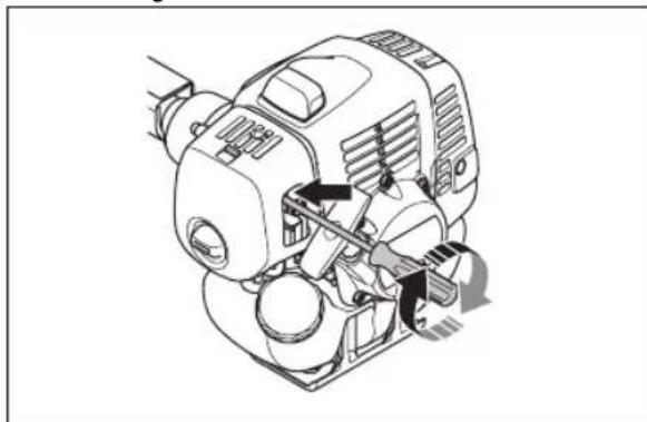
- Adjust the idle speed with the idle speed screw T which is identified with "T" mark.
a) Turn the idle speed screw T clockwise until the cutting attachment starts to rotate.
natural_image
Technical line drawing of a mechanical device with no visible text or symbolsb) Turn the idle speed screw T counterclockwise until the cutting attachment stops.

WARNING: If the cutting attachment does not stop when you adjust the idle speed, speak to your servicing dealer. Do not use the product until it is correctly adjusted or repaired.
- The idle speed is correct when the engine operates smoothly in all positions. The idle speed must be below the speed when the cutting attachment starts to rotate.
Note: Refer to Technical data on page 23 for the recommended idle speed.
Cooling system
The product has a cooling system to keep the work temperature low.
The cooling system has:
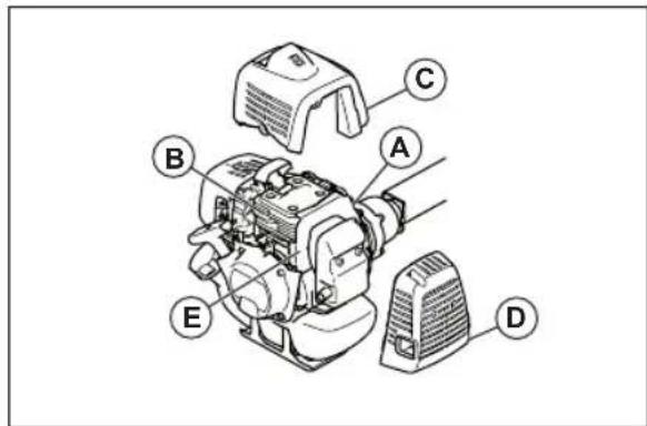
• Fins on the flywheel (A)
• Cooling fins on the cylinder (B)
• Cylinder cover (C) (directs cold air over the cylinder)
- Muffler cover (D)
- Muffler plate (E)
To clean the cooling system

WARNING: A dirty or blocked cooling system causes overheating. It causes damage to the piston and cylinder.
- Clean the parts of the cooling system with a brush a minimum of one time a week.
Air filter
- Clean the filter at intervals of 25 hours. Clean more regularly if necessary.
- Set the choke control in the choke position.

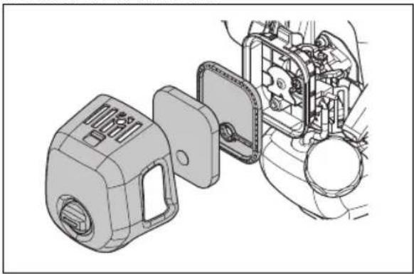
To clean the air filter
Clean the filter at intervals of 25 hours. Clean more regularly if it is necessary.

CAUTION: Always replace an air filter that is damaged, very dirty or soaked with fuel.
If you use an air filter for a long time, it cannot be fully cleaned. Replace the air filter with a new one at regular intervals.
- Close the choke valve.
natural_image
Technical line drawing of a mechanical device with no visible text or symbols- Remove the air filter cover.
natural_image
Technical line drawing of a mechanical assembly with exploded view of internal components (no text or symbols)- Remove the air filter.
- Clean the air filter with warm soap water.
- Replace the air filter if it is too dirty to fully clean it. Always replace a damaged air filter.
- Clean the inner surface of the air filter cover. Use air or a brush.
- Make sure that the air filter is dry.
- Use Husqvarna two-stroke oil to put oil on the air filter. If there is too much oil on the air filter, remove the unwanted oil before you install the air filter.
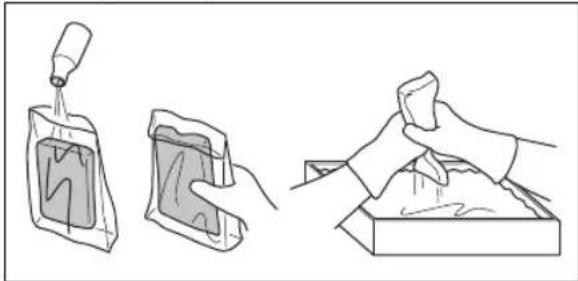
To apply oil to the foam air filter

CAUTION: Always use Husqvarna special air filter oil. Do not use other types of oil.

WARNING: Put on protective gloves. The air filter oil can cause skin irritation.
- Put the foam air filter in a plastic bag.
-
Put the oil in the plastic bag.
-
Rub the plastic bag to supply the oil equally across the foam air filter.
- Push the unwanted oil out of the foam air filter while in the plastic bag.
natural_image
Three-step illustration showing a bottle being poured into a container, a cloth swab, and a cloth covering a tray (no text or symbols)Felt filter
- Hit the felt filter carefully against your hand or use compressed air to clean the felt filter.

CAUTION: Do not use water to clean the felt filter. Water can cause damage to the felt filter.
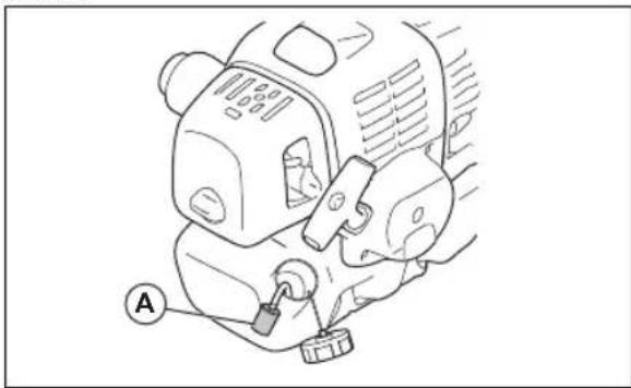
Fuel filter
When the engine runs short of fuel supply, make sure that the fuel tank cap and the fuel filter (A) is not blocked.
natural_image
Line drawing of a mechanical device with a labeled component (A) and no visible text or symbolsTo add grease to the bevel gear
• Make sure that the bevel gear is filled 34 full with bevel gear grease.
natural_image
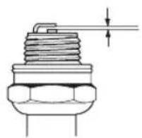
Technical line drawing of a mechanical assembly with two rods and a central component, showing no text or symbols.To examine the spark plug

CAUTION: Always use the recommended spark plug type. Incorrect spark plug type can cause damage to the product.
- Examine the spark plug if the engine is low on power, is not easy to start or does not operate correctly at idle speed.
• To decrease the risk of unwanted material on the spark plug electrodes, obey these instructions:
a) Make sure that the idle speed is correctly adjusted.
b) Make sure that the fuel mixture is correct.
c) Make sure that the air filter is clean.
- If the spark plug is dirty, clean it and make sure that the electrode gap is correct, refer to Technical data on page 23.
- Replace the spark plug if it is necessary.
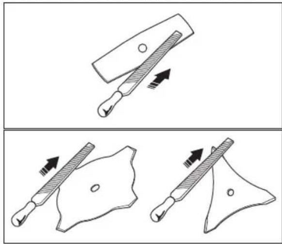
To sharpen grass cutters and grass blades
- Sharpen all edges of the grass cutters and blades equally to keep the balance. Use a single-cut flat file.
natural_image
Illustration of two different types of tools or pliers, showing different movement directions (no text or symbols present)Troubleshooting
Troubleshooting
| Starting failure | ||
| Check Possible cause Solution | ||
| Stop button Stop position Set the stop switch to the start position. | ||
| Starter pawls Binding pawls Adjust or replace the pawls. | ||
| Fuel tank Incorrect fuel type. | Drain it and use correct fuel. | |
| Carburetor Adjustment of the idle speed. | Adjust the idle speed with the T screw. | |
| Spark (no spark) | Spark plug dirty or wet. | Make sure that the spark plug is dry and clean. |
| Spark plug clearance incorrect. | Clean the spark plug. Check that the electrode gap is correct. Make sure that the spark plug is installed with a suppressor. | |
| Refer to technical data for correct electrode gap. | ||
| Spark plug Spark plug loose. | Tighten the spark plug. | |
| Fuel filter Clogged fuel filter. | Replace the fuel filter. | |
| Engine starts but does not stay running | ||
| Check Possible | cause Solution | |
| Fuel tank Incorrect type. | Drain it and use correct fuel. | |
| Carburetor Engine will not idle correctly. | Speak to your servicing dealer. | |
| Air filter Clogged | air filter. | Clean the air filter. |
| Fuel filter Clogged | fuel filter. | Replace the fuel filter. |
Transportation and storage
- Keep equipment safe during transportation to prevent damage and accidents.
- Keep the product and equipment in a dry and frost-proof area.
-
Clean the product.
-
Replace or repair damaged components.
- Use the correct protective cover on the product that does not keep moisture.
- Keep the product tightly attached during transport.
Technical data
Technical data
| 531RS 541RS 541RST | |||
| Engine | |||
| Cylinder displacement, cm^3 | 33.6 41.5 41.5 | ||
| Idle speed, rpm 2500±200 2500±200 2500±200 | |||
| Recommended max. speed, rpm 12000 12000 | 12000 | ||
| Speed of output shaft, rpm 8570 8570 8570 | |||
| Maximum engine power acc. to ISO 8893, kW/hp @ rpm | 1.2/1.6 @ 7000 1.6/2.1 | @ 7000 1.6/2.1 @ 7000 | |
| Ignition system | |||
| Spark plug NGK BPMR 7A NGK BPMR 7A | NGK BPMR 7A | ||
| Electrode gap, mm | 0.6-0.7 | 0.6-0.7 | 0.6-0.7 |
| Fuel and lubrication system | |||
| Fuel tank capacity, I/cm^3 | 0.74/740 0.94/940 0.94/940 | ||
| Weight | |||
| Weight, kg 6.9 7.1 7.3 | |||
| Noise emissions ^1 | |||
| Sound power level, measured, dB (A) 107 107 | 107 | ||
| Sound power level, guaranteed LWA, dB (A) 108 109 109 | |||
| Sound levels | |||
| Equivalent sound pressure level at the operator's ear, measured according to EN ISO 11806 and ISO 22868 ^2 | |||
| Equipped with trimmer head (original), dB (A) 90 94 94 | |||
| Equipped with grass blade (original), dB (A) 89 95 95 | |||
| Vibration levels | |||
| Equivalent vibration levels ( a_hv,eq ) at handles, measured according to EN ISO 11806 and ISO 22867 ^3 | |||
| Equipped with trimmer head (original), left/right, m/s^2 | 2.8/3.0 3.1/2.8 5.6/5.1 | ||
| Equipped with grass blade (original), left/right, m/s^2 | 4.2/4.0 4.5/5.0 7.1/6.3 | ||
Accessories
Accessories
| Approved accessories Accessory type | Cutting attachment guard, art. no. | |
| Grass blade/grass cutter Multi 255-3 (∅ 255, 3 teeth) 537 33 16-03 | ||
| Multi 275-4 (∅ 275, 4 teeth) 537 33 16-03 | ||
| Multi 300-3 (∅ 300, 3 teeth) 537 33 16-03 | ||
| Multi 330-2 (∅ 330, 2 teeth) 537 33 16-03 | ||
| Plastic blades Tricut ∅ 300 mm (Separate blades have part number 531 01 77-15) | 537 33 16-03 | |
| Approved accessories Accessory type | Cutting attachment guard, art. no. | ||
| Trimmer head T35, T35X (∅ 2.4-3.0 mm cord) 537 33 16-03 | |||
| S35 (∅ 2.4-3.0 mm cord) 537 33 16-03 | |||
| T45x (∅ 2.7-3.3 mm cord) 537 33 16-03 | |||
| T55x (∅ 2.7-3.3 mm cord) 537 33 16-03 | |||
| S II 537 33 16-03 | |||
| Support cup Fixed – | |||
EC Declaration of Conformity
EC Declaration of Conformity
Issuer's name: Husqvarna AB, SE-561 82 Huskvarna, Sweden, tel: +46-36-146500.
Husqvarna AB claims sole responsibility for the object of this declaration: Trimmer and/or Brushcutter powered by petrol, platform(s) G45L and G35L representing model(s) Husqvarna 531RS, 541RS and 541RST from 2017 serial numbers and onwards. The platform number and model number are clearly stated in plain text on the type plate along with the year with subsequent serial numbers.
The object of the declaration described above is in conformity with the requirements of the Council's Directives:
• of May 17, 2006 "relating to machinery" 2006/42/EC
• of February 26, 2014 "relating to electromagnetic compatibility" 2014/30/EU.
- of May 8, 2000 "relating to the noise emissions in the environment" 2000/14/EC.
• of December 14, 2005 "relating to the noise emissions in the environment" 2005/88/EC.
In accordance with Annex V, the declared sound values are stated in the technical data sheet of the operator's manual.
The following standards have been applied:
EN ISO 11806-1:2011, EN ISO 14982:2009, EN ISO 12100:2010 CISPR 12:2007+A1:2009
TÜV Rheinland LGA Products GmbH, Tillystrasse 2, D-90431 Nuernberg, Germany, 0197, has carried out a voluntary examination on behalf of Husqvarna AB, providing AM50391783 (541RS, 541RST), AM50391781 (531RS) - Certificate of Conformity to EC Council directive 2006/42/EC for machinery. This certificate is applicable to all manufacturing locations and Countries of Origin, as stated on the product. The supplied grass trimmer and/or brushcutter conforms to the example that underwent examination.
Husqvarna AB, Huskvarna, Sweden, 2020-08-25

Pär Martinsson, Development Manager (Authorized representative for Husqvarna AB and responsible for technical documentation.)
Contenido
Introducción.... 27
Seguridad....29
Montaje....35
natural_image
Illustration of a person using a long-handled tool to dig or brush outdoors, with a tree and grass nearby (no text or symbols)natural_image
Line drawing of a person in full protective suit holding a long tool, no text or symbols presentnatural_image
Line drawing of a mechanical device with an arrow indicating direction (no text or symbols)natural_image
Line drawing of a robotic arm with a directional arrow indicating motion (no text or symbols)natural_image
Line drawing of a handheld device with a black arrow pointing to the handle (no text or symbols)natural_image
Mechanical assembly diagram showing a lever and base component (no text or symbols)natural_image
Technical line drawing of a mechanical device with no visible text or symbolsnatural_image
Line drawing of a person adjusting a belt buckle, showing two hands and a belt buckle (no text or symbols)
natural_image
Line drawing of a mechanical switch or lever device (no text or symbols)natural_image
Illustration of a hand operating a mechanical component with a nut, showing rotational motion (no text or symbols)
natural_image
Four abstract geometric shapes with varying line styles and fill patterns (no text or symbols)natural_image
Two technical line drawings of mechanical components: a circular component with curved leads and a triangular plate with a slot (no text or symbols)natural_image
Diagram of a grater blade with an arrow indicating direction, no text or symbols presentnatural_image
Three technical line drawings of mechanical components: a cylindrical component with a loop, a flat plate with a circular cutout, and a coiled spring (no text or symbols)natural_image
Technical line drawing of a mechanical device with hoses and a central shaft (no text or symbols)- Instale el manguito protector.
natural_image
Technical line drawing of a mechanical device with a lever and cable, showing no text or symbolsnatural_image
Line drawing of a mechanical tool with a curved handle and lever, showing motion direction (no text or symbols)natural_image
Illustration of a person using a tool to clean or walk (no text or symbols present)- Instale la cubierta antipolvo (J).

natural_image
Technical diagram of a mechanical device with labeled component J, showing internal components and assembly (no text or symbols present)- Instale la cubierta del filtro de aire.
natural_image
Two mechanical components with a no-smoking symbol, one plain and one with a circular cross (no text or labels)natural_image
Line drawing of a hand holding a tool on a mechanical component (no text or symbols)natural_image
Line drawing of a hand using a screwdriver to adjust or install a mechanical part (no text or symbols)natural_image
Technical line drawing of a mechanical component with a curved arrow indicating rotation (no text or symbols)natural_image
Two identical mechanical components with labeled 'H' and rotational arrows, no text or symbols present.natural_image
Diagram showing three parallel plates with arrows indicating direction, no text or symbols presentnatural_image
Line drawing of a person wearing a helmet with downward arrows indicating pressure or stress (no text or symbols)natural_image
Technical line drawing of a mechanical device with a close-up inset showing a component detail (no text or symbols)natural_image
Illustration of a person in safety gear handling equipment (no text or symbols)natural_image
Technical line drawing of a mechanical device with an inset close-up showing a component (no text or symbols)natural_image
Line drawing of a mechanical tool or device with a handle and cable, no text or symbols presentnatural_image
Line drawing of a person walking on a path with trees and a curved road (no text or symbols)natural_image
Illustration of a hand operating a pulley system with a monkey on one side (no text or symbols)natural_image
Simple line drawing of a grassy field with a small utility pole and a tool, no text or symbols present.natural_image
Simple line drawing of a grassy field with a tool and a flat object (no text or symbols)natural_image
Simple line drawing of a grassy field with a tool and a shovel, no text or symbols presentnatural_image
Simple line drawing of a grassy field with a small mechanical component at the base (no text or symbols)natural_image
Diagram of a hand holding a mechanical lever with motion arrows indicating direction (no text or symbols)Barrer la hierba
natural_image
Technical line drawing of a mechanical device with no visible text or symbolsnatural_image
Technical line drawing of a mechanical device with a close-up inset showing a directional arrow (no text or symbols)natural_image
Technical line drawing of a mechanical device with no visible text or symbols- Saque la cubierta del filtro de aire.

natural_image
Technical line drawing of a mechanical assembly with exploded view of internal components (no text or symbols)natural_image
Three-step illustration showing a dropper being poured into a bag, a close-up of a container, and a hand holding a sample (no text or symbols)Filtro de fieltro
natural_image
Technical line drawing of a mechanical device with labeled component A (no text or symbols beyond label)natural_image
Technical line drawing of a mechanical component with a black arrow indicating a specific part (no text or symbols present)Para examinar la bujía

natural_image
Simple line drawing of a tool with a handle and arrow indicating direction (no text or symbols)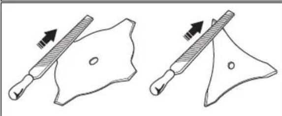
natural_image
Two diagrams showing a tool interacting with a shield-like object, one with an arrow indicating direction (no text or symbols present)natural_image
Illustration of a person using a long-handled tool to brush or brushstroke material, with a tree nearby (no text or symbols)natural_image
Line drawing of a person in full protective suit holding a long-handled tool (no text or symbols)natural_image
Line drawing of a robotic arm with directional arrow indicating movement (no text or symbols)natural_image
Line drawing of a mechanical device with an arrow indicating motion or force direction (no text or symbols)natural_image
Line drawing of a robotic arm with a handle and base, no text or symbols presentnatural_image
Technical line drawing of a mechanical component with no visible text or symbolsnatural_image
Mechanical assembly diagram showing a motor with adjustment lever and directional arrow (no text or labels)natural_image
Line drawing of a person adjusting a seatbelt with arrows indicating movement (no text or symbols)
natural_image
Line drawing of a mechanical switch or lever device (no text or symbols)natural_image
Illustration of a hand operating a mechanical component with a nut, showing rotational motion (no text or symbols)
natural_image
Four abstract geometric shapes with varying line styles and fill patterns (no text or symbols)natural_image
Two technical line drawings of mechanical components: a circular component with curved leads and a flat plate with a pointed tip (no text or symbols)natural_image
Simple line drawing of a tool and a shield-like object with an arrow indicating direction (no text or symbols)natural_image
Three technical line drawings of mechanical components: a cylindrical component with cable, a circular device with a handle, and a coiled spring (no text or symbols)natural_image
Technical line drawing of a mechanical device with articulated arms and a central shaft (no text or symbols)natural_image
Technical line drawing of a mechanical device with a lever and cable, showing no text or symbolsnatural_image
Line drawing of a mechanical tool with a curved handle and directional arrow (no text or symbols)natural_image
Illustration of a person using a tool to clean or walk, with no visible text or symbols- Instale a cobertura antipoeiras (J).
natural_image
Mechanical assembly diagram showing a motor and gear assembly with labeled component J (no text or symbols present)natural_image
Two mechanical components with a prohibition symbol (no text or labels present)natural_image
Line drawing of a hand holding a tool on a mechanical component (no text or symbols)natural_image
Line drawing of a hand using a screwdriver to adjust or install a mechanical part (no text or symbols)natural_image
Line drawing of a mechanical component with a curved arrow indicating motion (no text or symbols)natural_image
Two mechanical components with labeled H and rotational arrows, no text or symbols presentnatural_image
Diagram showing a mechanical or electrical component with three parallel plates and directional arrows indicating flow or movement (no text or symbols)Ajustar a correia

natural_image
Line drawing of a person wearing a helmet with downward arrows indicating downward pressure (no text or symbols)natural_image
Technical line drawing of a mechanical device with an inset close-up showing a component (no text or symbols)natural_image
Illustration of a worker in safety gear handling equipment (no text or symbols)natural_image
Technical line drawing of a mechanical device with an inset close-up showing a component (no text or symbols)natural_image
Line drawing of a mechanical tool or device with a handle and cable, no text or symbols presentOperar o aparador de relva

natural_image
Line drawing of a person walking on a path with trees and a curved road (no text or symbols)natural_image
Illustration of a hand using a tool to measure a pine tree, no text or symbols presentnatural_image
Simple line drawing of a grassy field with a small utility pole and a tool, no text or symbols present.natural_image
Simple line drawing of a grassy slope with a small utility pole (no text or symbols)natural_image
Simple line drawing of a grassy field with a tool and a flat object, no text or symbols present.Cortar a relva
natural_image
Simple line drawing of a grassy field with a small mechanical component at the base (no text or symbols)natural_image
Diagram of a hand operating a mechanical device with directional arrows indicating motion (no text or symbols)Para aparar a relva
natural_image
Technical line drawing of a mechanical device with no visible text or symbolsnatural_image
Diagram of a camera with a screwdriver and directional arrows indicating motion (no text or symbols)natural_image
Technical line drawing of a mechanical device with no visible text or symbolsnatural_image
Technical line drawing of a mechanical assembly with a component housing and internal components (no text or symbols)natural_image
Three-step illustration showing a dropper being poured into a container, then holding a cloth over a tray (no text or symbols)Filtro de feltro
natural_image
Illustration of a person using a lock device to adjust or install a device (no text or symbols visible)natural_image
Technical line drawing of a mechanical component with a black arrow indicating a specific part (no text or symbols present)Afiar as lâminas e as cortadoras de relva
natural_image
Simple line drawing of a tool with a handle and arrow indicating direction (no text or symbols)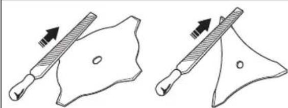
natural_image
Two diagrams showing a tool interacting with a shield-like shape, one with an arrow indicating direction (no text or symbols present)natural_image
Illustration of a person using a power tool to spray or brush near a tree (no text or symbols)natural_image
Line drawing of a person in full protective suit holding a long-handled tool (no text or symbols)natural_image
Line drawing of a robotic arm with directional arrows indicating movement or force (no text or symbols)natural_image
Line drawing of a handheld industrial tool with a directional arrow indicating motion (no text or symbols)natural_image
Line drawing of a mechanical device with a knob and threaded base (no text or symbols)natural_image
Technical line drawing of a mechanical component with a base and shaft (no text or symbols)natural_image
Technical line drawing of a mechanical device with no visible text or symbolsnatural_image
Line drawing of a person adjusting a belt buckle, showing two hands and one belt buckle (no text or symbols)Проверка глушителя


natural_image
Line drawing of a mechanical device with two circular buttons and a handle (no text or symbols)natural_image
Line drawing of a mechanical switch or lever device (no text or symbols)natural_image
Illustration of a hand operating a propeller with a nut, accompanied by a rotation arrow indicating rotational motion (no text or symbols)
natural_image
Four abstract geometric shapes with varying line styles and dot patterns, no text or symbols present.natural_image
Two technical line drawings of mechanical components: a circular component with curved leads and a flat plate with a central slot (no text or symbols)natural_image
Simple line drawing of a halter with a handle and arrow indicating direction (no text or symbols)natural_image
Line drawings of three mechanical components: a cylindrical device, a flat plate with a circular cutout, and a spool (no text or symbols)natural_image
Technical line drawing of a mechanical device with articulated arms and a central motor (no text or symbols)natural_image
Mechanical diagram showing a tool interacting with a motor or pump assembly (no text or symbols visible)Установка рукоятки (541RST)
natural_image
Line drawing of a mechanical tool with a downward arrow indicating motion (no text or symbols)natural_image
Illustration of a person using a tool to measure a circular object, no text or symbols presentnatural_image
Two mechanical components with a prohibition symbol (no text or labels present)natural_image
Line drawing of a hand holding a tool on a mechanical component (no text or symbols)natural_image
Line drawing of a hand using a tool to adjust or install a device with a strap (no text or symbols)natural_image
Line drawing of a hand using a tool to adjust or install a mechanical component (no text or symbols present)natural_image
Two identical mechanical components with curved blades and labeled H, shown in side-by-side views (no text or symbols present)natural_image
Diagram showing three parallel grooves with a central oval and directional arrows indicating flow or movement (no text or symbols)natural_image
Line drawing of a person wearing a helmet and safety vest, with downward arrows indicating downward pressure (no text or symbols)natural_image
Technical line drawing of a mechanical device with an inset showing a close-up of a component (no text or symbols present)natural_image
Illustration of a person in safety gear handling equipment (no text or symbols)natural_image
Technical line drawing of a mechanical device with a close-up inset showing a component detail (no text or symbols)natural_image
Line drawing of a mechanical tool or device with a pointed tip and threaded base (no text or symbols)natural_image
Line drawing of a person spraying water on a path with trees and a dashed line (no text or symbols)natural_image
Illustration of a person using a pulley system to lift a tree (no text or symbols)natural_image
Simple line drawing of a grassy field with a small water feature, no text or symbols presentnatural_image
Simple line drawing of a grassy slope with a small shrub and a tool, no text or symbols present.natural_image
Simple line drawing of a grassy field with a small tool and a flat object, no text or symbols present.Кошение травы
natural_image
Simple line drawing of a grassy field with a small mechanical component at the base (no text or symbols)natural_image
Diagram of a hand holding a mechanical device with directional arrows indicating motion (no text or symbols)Уборка травы
natural_image
Technical line drawing of a mechanical device with no visible text or symbolsnatural_image
Diagram of a camera with a screwdriver inserted, showing alignment instructions (no text or symbols)natural_image
Technical line drawing of a mechanical device with no visible text or symbolsnatural_image
Technical line drawing of a mechanical assembly with exploded view of internal components (no text or symbols)natural_image
Three-step line drawing showing a spray bottle pouring liquid into a container, a plastic bag with a handle, and a hand cleaning a surface (no text or symbols)Войлочный фильтр
natural_image
Line drawing of a mechanical device with a labeled component (A) and motion indicators, no readable text or symbols present.natural_image
Technical line drawing of a mechanical component with a black arrow indicating a specific part (no text or symbols present)natural_image
Technical line drawing of a mechanical component with threaded body and shaft (no text or symbols)natural_image
Illustration of two different types of tools or pliers, showing different movement directions (no text or symbols present)natural_image
Line drawing of a person using a long-handled tool to shoot grass near a tree (no text or symbols)natural_image
Line drawing of a person in full protective suit holding a long pole (no text or symbols)natural_image
Technical line drawing of a mechanical tool or device with directional arrows indicating movement (no text or symbols)natural_image
Technical line drawing of a mechanical tool with an arrow indicating motion (no text or symbols)natural_image
Line drawing of a mechanical tool or device with a handle and cable, no text or symbols presentnatural_image
Technical line drawing of a mechanical component with a base and shaft (no text or symbols)natural_image
Technical line drawing of a mechanical device with no visible text or symbolsnatural_image
Illustration of a person adjusting a belt buckle, showing hand positioning and belt movement (no text or symbols)Перевірка глушника


natural_image
Line drawing of a mechanical switch or lever device (no text or symbols)natural_image
Illustration of a hand using a pulley tool to lift a nut, with a separate rotation arrow indicating clockwise motion (no text or symbols)
natural_image
Four abstract geometric shapes with no text or symbols: triangular, rectangular, and irregular forms (no text or symbols present)natural_image
Two technical line drawings of mechanical components: a circular component with curved leads and a flat plate with a pointed tip (no text or symbols)natural_image
Simple line drawing of a tool and a shield-like object (no text or symbols)natural_image
Three technical illustrations of household appliances: a cylindrical fan, a square plate with a circular cutout, and a spool (no text or symbols)natural_image
Technical line drawing of a mechanical device with articulated arms and a central shaft (no text or symbols)natural_image
Mechanical device diagram showing a lever mechanism with a handle and labeled component (no text or symbols present)natural_image
Line drawing of a mechanical tool with a curved handle and arrow indicating motion (no text or symbols)natural_image
Illustration of a person using a long-handled tool with a rotating arrow (no text or symbols)natural_image
Mechanical assembly diagram showing a motor and gear assembly with labeled component J (no text or symbols present)natural_image
Two technical diagrams showing a mechanical component with a prohibition symbol (no text or labels present)natural_image
Line drawing of a hand holding a tool, partially open the handle (no text or symbols)natural_image
Line drawing of a hand using a screwdriver to adjust or install a small mechanical part (no text or symbols)natural_image
Technical line drawing of a mechanical component with a curved arrow indicating rotation (no text or symbols)natural_image
Two identical mechanical components with labeled H and rotational arrows, no text or symbols present.natural_image
Diagram showing three parallel plates with arrows indicating direction, no text or symbols presentnatural_image
Line drawing of a person wearing a helmet and holding an object, with no visible text or symbolsnatural_image
Technical line drawing of a mechanical device with a close-up inset showing a component (no text or symbols)natural_image
Illustration of a worker in safety gear handling equipment (no text or symbols)natural_image
Technical line drawing of a mechanical device with a close-up inset showing a component detail (no text or symbols)natural_image
Line drawing of a mechanical device with a handle and base, no text or symbols presentflowchart
graph TD
    A["Start"] --> B{Growth Path}
    B -->|Yes| C["Plant Growth"]
    B -->|No| D["Growth Path"]
    C --> E["Leafy Branch 1"]
    C --> F["Leafy Branch 2"]
    D --> G["Leafy Branch 3"]
    D --> H["Leafy Branch 4"]
    E --> I["Leafy Branch 5"]
    F --> J["Leafy Branch 6"]
    G --> K["Leafy Branch 7"]
    H --> L["Leafy Branch 8"]
natural_image
Line drawing of a person walking on a path with trees and a curved road (no text or symbols)natural_image
Illustration of a hand using a tool to measure a pine branch with a handle (no text or symbols)natural_image
Simple line drawing of a grassy field with a small shrub and a small tool nearby (no text or symbols)natural_image
Simple line drawing of a grassy slope with a tool, no text or symbols presentnatural_image
Simple line drawing of a grassy field with a tool and a small object, no text or symbols present.Зрізання трави
natural_image
Simple line drawing of a grassy field with a small mechanical component and two vertical rods (no text or symbols)natural_image
Diagram of a hand holding a mechanical lever with directional arrows indicating motion (no text or symbols)Підмітання трави
natural_image
Technical line drawing of a mechanical device with no visible text or symbolsnatural_image
Diagram of a mechanical device with a tool and directional arrow, no readable text or symbols present.natural_image
Technical line drawing of a mechanical device with no visible text or symbolsnatural_image
Technical line drawing of a mechanical assembly with exploded view (no text or symbols)natural_image
Three-step illustration showing a bottle being poured into a container, then holding a cloth over a tray (no text or symbols)Повстяний фільтр
natural_image
Technical line drawing of a mechanical device with labeled component A (no text or symbols beyond label)natural_image
Technical line drawing of a mechanical component with a directional arrow indicating motion (no text or symbols)natural_image
Simple line drawing of a cutting tool with an arrow indicating direction (no text or symbols)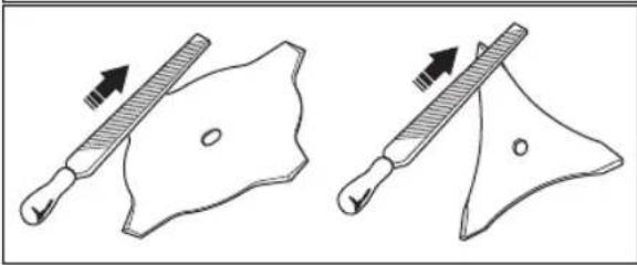
natural_image
Two diagrams showing a tool interacting with a shield-like object, one with an arrow indicating direction (no text or symbols present)natural_image
Illustration of a person using a shoveling tool to spray or brush (no text or symbols present)natural_image
Line drawing of a person in full protective suit holding a long-handled tool (no text or symbols)natural_image
Line drawing of a mechanical device with an arrow indicating direction (no text or symbols)natural_image
Line drawing of a robotic arm with a curved handle and arrow indicating motion (no text or symbols)natural_image
Line drawing of a handheld industrial tool with a handle and screw base (no text or symbols)natural_image
Technical line drawing of a mechanical component with a base and shaft (no text or symbols)natural_image
Technical line drawing of a mechanical device with no visible text or symbolsnatural_image
Line drawing of a person adjusting a seatbelt with arrows indicating motion (no text or symbols)
natural_image
Line drawing of a mechanical switch or lever device (no text or symbols)natural_image
Illustration of a hand using a tool to adjust a mechanical component, with a separate diagram showing rotational motion (no text or symbols)
natural_image
Four abstract geometric shapes with varying line styles and fill patterns (no text or symbols)natural_image
Two technical line drawings of mechanical components: a circular component with curved leads and a triangular plate with a pointed tip (no text or symbols)natural_image
Simple line drawing of a tool and a shield-like object with an arrow indicating direction (no text or symbols)natural_image
Three technical line drawings of mechanical components: a cylindrical component, a square plate with a circular cutout, and a coiled spring (no text or symbols)natural_image
Technical line drawing of a mechanical device with articulated arms and a motor (no text or symbols)natural_image
Mechanical diagram showing a tool interacting with a motor or actuator (no text or symbols present)Pour poser le guidon (541RST)
natural_image
Line drawing of a mechanical tool with a downward arrow indicating motion (no text or symbols)natural_image
Illustration of a person using a tool to clean or walk (no text or symbols present)natural_image
Technical diagram of a mechanical device with labeled component J, showing internal components and wiring (no text or symbols present)natural_image
Two mechanical components with a prohibition symbol (no text or labels present)natural_image
Line drawing of a hand holding a tool on a mechanical component (no text or symbols)natural_image
Line drawing of a hand using a screwdriver to adjust or install a small mechanical component (no text or symbols)natural_image
Line drawing of a hand holding a mechanical component with a curved arrow indicating motion (no text or symbols)natural_image
Two mechanical components with labeled H and rotational arrows, no text or symbols presentnatural_image
Diagram showing three parallel plates with arrows indicating direction, no text or symbols presentnatural_image
Cartoon illustration of a person wearing a hard hat with downward arrows indicating pressure or stress (no text or symbols)natural_image
Technical line drawing of a mechanical device with a close-up inset showing a component detail (no text or symbols)- Amenez la commande de starter en position de starter.
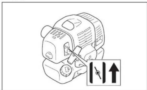
natural_image
Illustration of a worker in safety gear handling equipment (no text or symbols visible)natural_image
Technical line drawing of a mechanical device with an inset showing a close-up of a component (no text or symbols present)natural_image
Line drawing of a mechanical device with labeled component A (no text or symbols beyond label)natural_image
Line drawing of a mechanical device with a handle and base, no text or symbols presentnatural_image
Simple line drawing of a person walking on a path with trees and a curved road (no text or symbols)natural_image
Illustration of a hand using a tool to measure a pine branch with a measuring instrument (no text or symbols present)natural_image
Simple line drawing of a grassy field with a small utility pole and a tool, no text or symbols present.natural_image
Simple line drawing of a grassy field with a small tool or scraper (no text or symbols)natural_image
Simple line drawing of a grassy field with a shovel and stick, no text or symbols presentPour couper l'herbe
natural_image
Simple line drawing of a grassy field with a small circular object on top (no text or symbols)natural_image
Diagram of a hand holding a mechanical lever with directional arrows indicating motion (no text or symbols)natural_image
Technical line drawing of a mechanical device with no visible text or symbolsnatural_image
Technical line drawing of a mechanical device with no visible text or symbolsnatural_image
Technical line drawing of a mechanical assembly with exploded view of internal components (no text or symbols)natural_image
Three-step illustration showing a bottle being poured into a container, then holding a cloth over a tray (no text or symbols)Filtre en feutre
natural_image
Line drawing of a mechanical device with labeled component A, showing internal components and motion lines (no text or symbols)natural_image
Technical line drawing of a mechanical component with a black arrow indicating a specific part (no text or symbols present)natural_image
Technical line drawing of a spark plug with threaded shaft and base (no text or symbols)natural_image
Illustration of three different tools: a cutting tool, a blade with arrows indicating motion, and a triangular tool with arrows indicating force (no text or symbols present)Dépannage
Dépannage
-
Nož (nije dostupan za sva tržišta)
-
Dugme gasa pri pokretanju
-
Poklopac za sipanje maziva, menjač ugla
-
Prekidač za zaustavljanje
-
Menjač ugla
-
Kontrola gasa
-
Štitnik priključka za košenje
-
Kočnica gasa
-
Osovina
-
Prsten vešanja
-
Poklopac cilindra
-
Ručica užeta startera
-
Rezervoar za gorivo
-
Kontrola čoka
-
Poklopac filtera za vazduh
-
Drška (531RS, 541RS)
-
Poklopac kvačila
-
Stezna navrtka
-
Oslona šolja
-
Oslona prirubnica
-
Upravljački zahvatnik
-
Stezaljka drške (531RS, 541RS)
-
Korisničko uputstvo
-
Transportni štitnik (nije dostupan za sva tržišta)
-
Ključ
-
Ključ
-
Blokirajuća osovinica (za proizvode bez imbus ključa)
-
Uprtač
-
Pumpa za vazduh
-
Produžetak štitnika
-
Glava trimera
-
Šestougaoni ključ
-
2-zubi nož
-
Poklopac (541RST)
-
Nosač (541RST)
-
Drška (541RST)
-
Zaštitna čaura
-
Dugme (541RST)
Simboli na proizvodu

UPOZORENJE: Ovaj proizvod može biti opasan i prouzrokovati teške povrede ili smrt rukovaoca ili drugih osoba. Budite pažljivi i koristite proizvod na pravilan način.

natural_image
Line drawing of a person digging with a shovel, no text or symbols present- Uverite se da nema opasnosti od pada prilikom korišćenja proizvoda. Nemojte se naginjati kada radite sa proizvodom.
- Uvek držite proizvod sa obe ruke. Držite proizvod sa desne strane tela.

natural_image
Line drawing of a person in full protective suit using a long-handled tool (no text or symbols)- Radite sa proizvodom tako da vam je priključak za košenje ispod struka.
- Ako je kontrola čoka u položaju čoka prilikom pokretanja motora, priključak za košenje će početi da se okreće.
- Nemojte dodirivati menjač ugla nakon zaustavljanja motora. Menjač ugla je vruć nakon zaustavljanja motora. Vruće površine mogu da izazovu telesnu povredu.
- Zaustavite motor pre nego što pomerite proizvod.
• Nemojte spuštati proizvod kada motor radi. - Pre uklanjanja neželjenih materijala sa proizvoda, zaustavite motor i sačekajte da se priključak za košenje zaustavi. Sačekajte da se priključak za košenje zaustavi pre nego što vi ili osoba koja vam pomaže u radu uklonite isečeni materijal.
Lična zaštitna oprema

UPOZORENJE: Pročitajte upozoravajuća uputstva koja slede pre korišćenja proizvoda.
- Uvek koristite odgovarajuću ličnu zaštitnu opremu kada radite sa proizvodom. Lična zaštitna oprema ne poništava rizik od telesne povrede. Lična zaštitna oprema umanjuje stepen telesne povrede u slučaju pojave nesreće.
- Uvek koristite odobrenu zaštitu za oči tokom rada sa proizvodom.
- Nemojte raditi sa proizvodom dok ste bosonogi ili u otvorenoj obući. Uvek nosite nekližuće i čvrste čizme.
- Uvek nosite duge pantalone od čvrstog materijala.
- Ako je neophodno, koristite odobrene zaštitne rukavice.
- Nosite zaštitnu kacigu ako postoji mogućnost da vam predmeti padnu na glavu.
- Uvek koristite odobrenu zaštitu za uši tokom rada sa proizvodom. Izloženost buci tokom dužeg vremenskog perioda može dovesti do gubitka sluha izazvanog bukom.
- Vodite računa da vam u blizini bude komplet za prvu pomoć.
Zaštitni uređaji na proizvodu
natural_image
Line drawing of a robotic arm with directional arrows indicating movement (no text or symbols)- Uverite se da je obarač gasa zaključan u praznom hodu kada je zaključavanje obarača gasa otpušteno.
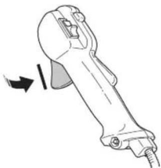
natural_image
Line drawing of a mechanical tool with an arrow indicating motion (no text or symbols)-
Pokrenite proizvod i dajte puni gas.
-
Otpustite obarač gasa i uverite se da se priključak za košenje zaustavlja i ne nastavlja da se kreće.

UPOZORENJE: Ako se priključak za košenje kreće dok je obarač gasa u praznom hodu, morate da podesite brzinu praznog hoda karburatora. Pogledajte Podešavanje brzine praznog hoda na stranici 179.
Da biste proverili rad prekidača za zaustavljanje
-
Pokrenite motor.
-
Pomerite prekidač za zaustavljanje u položaj za zaustavljanje i proverite da li se motor zaustavio.
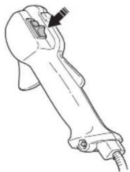
natural_image
Line drawing of a mechanical device with a knob and handle (no text or symbols)Da biste proverili štitnik priključka za košenje
Štitnik priključka za košenje sprečava da dođe do povreda i zaustavlja predmete koji su izbačeni u smeru rukovaoca.
- Zaustavite motor.
- Izvršite vizuelni pregled u pogledu oštećenja, na primer, naprslina.
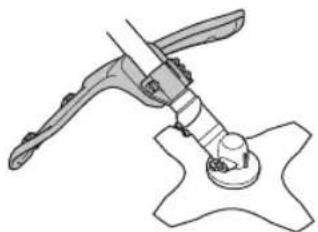
natural_image
Diagram of a mechanical assembly with a lever and base component (no text or symbols)natural_image
Technical line drawing of a mechanical device with no visible text or symbols- Zaustavite motor.
-
Izvršite vizuelni pregled deformacija i oštećenja, poput naprslina.
-
Vodite računa o pravilnom postavljanju elemenata sistema za ublažavanje vibracija.
Da biste izvršili pregled mehanizma za brzo oslobađanje

natural_image
Illustration of a person adjusting a seatbelt with arrows indicating force direction (no text or symbols)Da biste proverili prigušivač


UPOZORENJE: Imajte na umu da su izduvni gasovi motora vrući i mogu sadržati varnice koje mogu da izazovu požar. Nikada nemojte pokretati proizvod u zatvorenom prostoru ili u blizini zapaljivih materijala!
Prigušivač održava nivoe buke na minimumu i šalje izduvne gasove od rukovaoca. Za prigušivače je veoma važno da pratite uputstva o tome kako da proverite, održavate i servisirate proizvod.
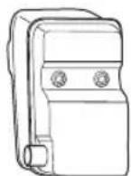
natural_image
Line drawing of a mechanical switch or lever device (no text or symbols)natural_image
Illustration of a hand using a tool to adjust a mechanical component, with a separate diagram showing rotational motion (no text or symbols)
natural_image
Four abstract geometric shapes with varying line styles and fill patterns (no text or symbols)- Glavu trimera koristite za podrezivanje trave.
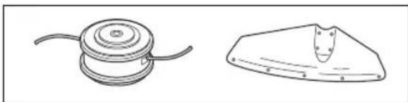
natural_image
Two technical line drawings of mechanical components: a circular component with curved leads and a triangular plate with a central slot (no text or symbols)- Pogrešno naoštren ili oštećen list testere povećava opasnost od nesrećnih slučajeva. Održavajte zube sečiva u dobrom stanju i propisno naoštrene. Pridržavajte se uputstava koje navodi Održavanje na
stranici 177 i koristite preporučenu turpiju za oštrenje.
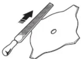
natural_image
Simple line drawing of a tool interacting with a shield-like object (no text or symbols)natural_image
Three technical line drawings of household appliances: a cylindrical fan, a washing machine, and a spool (no text or symbols)- Koristite samo preporučene priključke za košenje.
- Dužina strune trimera je važna. Ako koristite dužu nit trimera, potrebna je veća snaga motora nego za kraću nit istog prečnika.
- Ne menjajte originalni položaj štitnika trimera.
- Proverite da li je nož koji se nalazi na štitniku trimera neoštećen. Time se struna trimera skraćuje na ispravnu dužinu.
- Natapajte strunu trimera 2 dana pre upotrebe, da biste joj produžili vek.
natural_image
Technical line drawing of a mechanical device with articulated arms and a central hub (no text or symbols)- Postavite zaštitnu čauru.
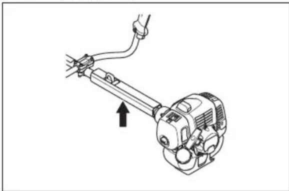
natural_image
Mechanical assembly diagram showing a motor with attached cable and spring, no text or symbols presentPostavljanje ručice (541RST)
- Uklonite zavrtanj iza držača regulatora gasa.
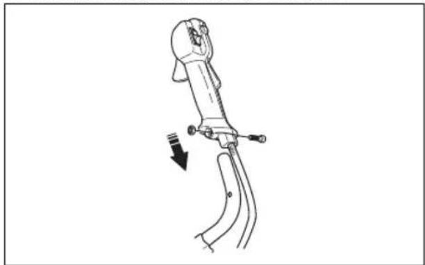
natural_image
Line drawing of a robotic arm with a curved handle and lever, showing motion direction (no text or symbols)- Postavite steznik drške (A), poklopac (B) i točkić (C).
- Poravnajte otvore za zavrtanj točkića.
- Pritegnite točkić tako da dobro stegnete dršku.
Postavljanje uprtača
-
Namestite uprtač i obesite proizvod na tačku vešanja.
-
Podesite ručicu kako biste postavili proizvod u udoban radni položaj.
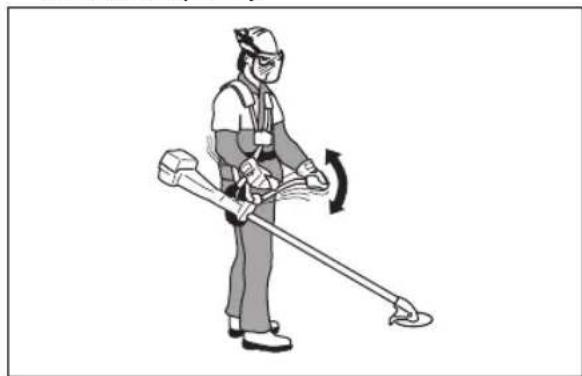
natural_image
Illustration of a person using a tool to clean or walk (no text or symbols present)- Pritegnite zavrtnje do kraja.
Povezivanje sajle gasa i vodova prekidača za zaustavljanje
- Uklonite poklopac filtera za vazduh.
- Provedite sajlu gasa (A) kroz nosač karburatora (B).
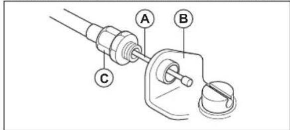
- Uvrnite rukavac za podešavanje sajle (C) do kraja u karburator.
- Stavite umetak sa žlebom (D) na karburator. U tom trenu, upušteni otvor (E) za ušku kabla (F) se nalazi sa dalje strane rukavca za podešavanje sajle (C).
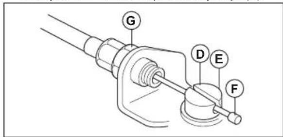
- Rotirajte ekscentrični točak gasa karburatora i provucite sajlu gasa (A) kroz otvor u umetku sa žlebom.
- Uverite se da uška kabla (F) upada u upušteni otvor.
- Povucite obarač gasa nekoliko puta da biste proverili da li pravilno radi.
- Podesite rukavac za podešavanje sajle (C).
a) Uverite se da graničnik na ekscentričnom točku gasa karburatora pravilno naleže na graničnik gasa.
b) Uverite se da je položaj sajle takav da se nalazi 1–2 mm između uške kabla (F) i umetka sa žlebom kad je obarač gasa potpuno pušten.
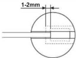
- Kad pravilno podesite sajlu gasa (A), pritegnite blokirajuću navrtku (G).
- Povežite kablove prekidača za zaustavljanje (H) sa priključcima iz motora.
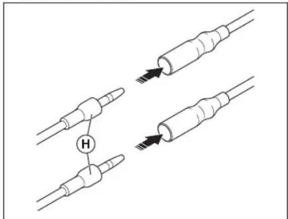
- Postavite prašinar (J).
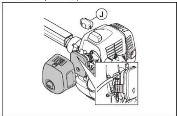
natural_image
Mechanical assembly diagram showing a motor with labeled joint (J) and close-up detail of internal components (no text or symbols present)- Postavite poklopac vazdušnog filtera.
Postavljanje listova i trimi glava

UPOZORENJE: Koristite samo odobreni štitnik za rezne listove. Pogledajte Oprema na stranici 184. Oštećeni štitnik može da izazove telesnu povredu.

natural_image
Two technical diagrams showing a mechanical component with a prohibition symbol (no text or labels present)Pričvršćivanje i uklanjanje produžetka štitnika
Produžetak štitnika se koristi na štitniku nastavka za rezanje. Postavite produžetak štitnika kada koristite trimi glavu ili plastične rezne listove. Uklonite produžetak štitnika kada koristite list za travu.
- Postavite vodicu na produžetku štitnika u otvor na štitniku nastavka za rezanje. Pritisnite 4 kuke za zaključavanje u zaključan položaj.
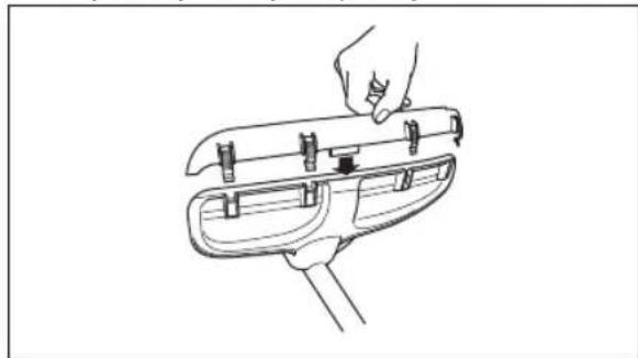
natural_image
Line drawing of a hand holding a tool on a mechanical component (no text or symbols)- Otpustite kuke za zaključavanje pomoću odvijača da biste uklonili produžetak štitnika.
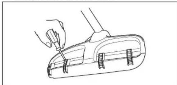
natural_image
Line drawing of a hand using a screwdriver to adjust or install a small mechanical component (no text or symbols)Postavljanje zaštite reznog lista, lista za košenje trave i noža za košenje trave

- Postavite zahvatnik (B) na izlaznoj osovini.
- Okrećite izlaznu osovinu sve dok se jedan od otvora na zahvatniku ne izravna sa odgovarajućim otvorom na kućištu menjača.
- Stavite trn za osiguranje ili imbus ključ (C) u otvor tako da se osovina osigura.
- Postavite sečivo (D), oslonu prirubnicu (E) i oslonu šolju (F) na izlaznu osovinu.
- Postavite navrtku (G). Pomoću kombinovanog ključa pritegnite navrtku na moment zatezanja od 35–50 Nm. Držite dršku kombinovanog ključa što je moguće bliže zaštiti reznog lista.
- Navrtka se priteže kada se kombinovani ključ okreće suprotno od smera rotacije.
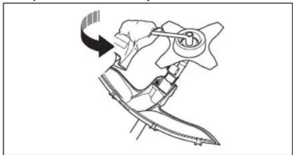
natural_image
Line drawing of a hand holding a mechanical component with a tool, no text or symbols presentnatural_image
Two mechanical components with labeled H and rotational arrows, no text or symbols present- Sastavite glavu trimera / plastične rezne listove (H). Okrećite glavu trimera / plastične rezne listove ulevo.
- Demontaža se vrši obrnutim redosledom.
Postavljanje štitnika za transportovanje
- Postavite nož u transportni štitnik (A).
- Stavite dva pričvršćivača (B) u otvore (C) da biste postavili transportni štitnik.
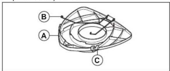
Da biste postavili 2-zubi nož u štitnik
- Postavite nož u transportni štitnik.

natural_image
Diagram showing three parallel plates with arrows indicating direction, no text or symbols presentPodešavanje uprtača

natural_image
Line drawing of a person wearing a helmet and holding an object, with no visible text or symbols- Podesite uprtač tako da priključak za košenje bude paralelan sa tlom.
- Pustite da priključak za košenje lako dodirne tlo. Podesite stezaljku uprtača da biste ispravno balansirali proizvod.
Napomena: Ako koristite list za travu, morate ga balansirati približno 10 cm / 4 inča iznad tla.
Rukovanje

natural_image
Technical line drawing of a mechanical clamp or grip assembly with an inset showing a close-up of the component (no text or symbols present)- Pomerite kontrolu čoka u položaj čoka.
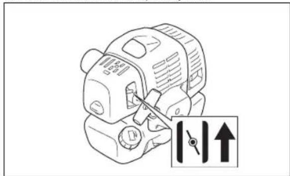
- Držite proizvod na tlu. Lagano izvlačite uže startera desnom rukom dok ne osetite određeni otpor.
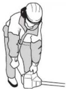
natural_image
Illustration of a worker in safety gear handling equipment (no text or symbols visible)Napomena: Nemojte namotavati uže startera oko ruke.

natural_image
Line drawing of a mechanical device with a close-up inset showing a component detail (no text or symbols)- Podesite kontrolu čoka u radni položaj, a zatim vucite uže startera dok se motor ne pokrene.
natural_image
Line drawing of a mechanical device with labeled component A (no text or symbols beyond label)Zaustavljanje motora
- Gurnite obarač gasa u položaj praznog hoda.
- Pomerite prekidač za zaustavljanje u položaj za zaustavljanje.
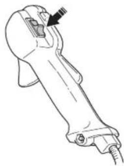
natural_image
Line drawing of a mechanical tool or device with a handle and base, no visible text or symbolsRad sa trimerom za travu

OPREZ: Pobrinite se da se motor uspori u brzinu praznog hoda nakon svakog rada. Dug period rada pri punom gasu bez opterećenja na motoru može izazvati oštećenje motora.
Napomena: Očistite poklopac trimi glave kada pričvrstite novu trimi nit kako biste sprečili vibracije. Pregledajte ostale delove trimi glave i očistite ih ako je potrebno.
natural_image
Simple line drawing of a person walking on a path with trees and a dashed line indicating a path (no text or symbols)- Krećite se duž nagiba, a ne gore i dole.
natural_image
Illustration of a hand using a tool to measure a pine branch with a handle (no text or symbols)- Kad raščišćavate travu, nagnite nož ulevo.
Napomena: Trava se lako skuplja u vodu.
- Za povratni rez koristite bočni pokret sleva nadesno.
- Radite ritmično.
- Pomerajte se napred i čvrsto stojte na zemlji.
- Zaustavite motor.
- Odvojte proizvod od kopče uprtača.
- Spustite proizvod na tlo.
- Skupite odrezani materijal.
Čišćenje
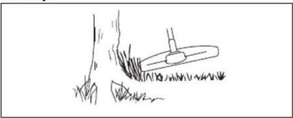
natural_image
Simple line drawing of a grassy field with a small utility pole, no text or symbols presentDa biste postigli najbolje rezultate:
- Držite trimer tako da glava trimera bude odmah iznad tla.
• Nagnite glavu trimera pod blagim uglom. - Pustite da kraj strune trimera udara tlo oko predmeta
Skraćivanje trave
- Držite glavu trimera odmah iznad tla i pod uglom. Nemojte pritiskati trimi nit u travu.

natural_image
Simple line drawing of a grassy field with a tool, no text or symbols present- Smanjite dužinu trimi niti za 10–12 cm / 4–4,75 inča.
-
Smanjite brzinu motora da biste smanjili rizik od oštećenja biljaka.
-
Koristite 80% gasa kada kosite travu blizu predmeta.
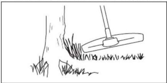
natural_image
Simple line drawing of a shovel digging grass with a stick nearby (no text or symbols)Košenje trave
- Pazite da struna trimera bude paralelna sa tlom prilikom košenja.
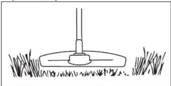
natural_image
Simple line drawing of a grassy field with a small circular object at the base (no text or symbols)- Nemojte pritiskati glavu trimera o tlo. Može doći do uništenja tla i oštećenja proizvoda.
- Nemojte dozvoliti da trimera glava neprestano dodiruje tlo, to može prouzrokovati oštećenje glave trimera.
- Koristite pun gas kada pomerate proizvod od ugla do ugla dok kosite travu.
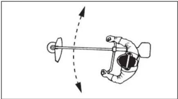
natural_image
Diagram of a hand operating a mechanical lever with directional arrows indicating motion (no text or symbols)Pometanje trave
Protok vazduha iz rotirajuće trimi niti može se koristiti za uklanjanje isečene trave iz područja.
- Držite trimi glavu i trimi nit paralelno sa tlom i iznad tla.
- Primenite pun gas.
- Pomerajte trimi glavu sa strane u stranu i raščišćavajte travu.

UPOZORENJE: Očistite poklopac trimi glave svaki put kada postavljate novu trimi nit kako biste sprečili neravnotežu i vibracije u ručicama. Takođe izvršite pregled drugih delova trimi glave i očistite ih po potrebi.
Zamena trimi niti
natural_image
Technical line drawing of a mechanical assembly with no visible text or symbols- Krilca na zamajcu (A)
• Krilca za hlađenje na cilindru (B) - Poklopac cilindra (C) (dovodi hladan vazduh na cilindar)
• Poklopac prigušivača (D) - Ploča prigušivača (E)
Čišćenje sistema za hlađenje

UPOZORENJE: Zaprljan ili zapušen sistem za hlađenje izaziva pregrevanje. To oštećuje klip i cilindar.
natural_image
Diagram of a mechanical device with a tool and directional arrow, no readable text or symbols present.Čišćenje filtera za vazduh
Čistite filter u intervalima od 25 sati. Po potrebi čistite češće.

natural_image
Technical line drawing of a mechanical device with no visible text or symbols- Uklonite poklopac filtera za vazduh.
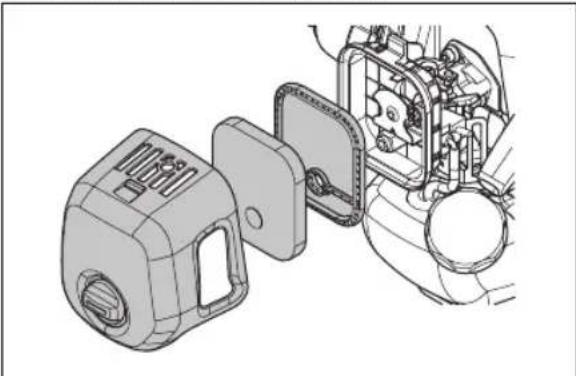
natural_image
Technical line drawing of a mechanical assembly with a component housing and internal components (no text or symbols)- Uklonite filter za vazduh.
- Očistite filter za vazduh toplom sapunjavom vodom.
- Zamenite filter za vazduh ako je previše zaprljan i ne može se propisno očistiti. Uvek zamenite oštećeni filter za vazduh.
- Očistite unutrašnju površinu poklopca filtera. Koristite vazduh ili četku.
- Uverite se da je filter za vazduh suv.
- Filter za vazduh podmažite Husqvarna uljem za dvotaktne motore. Ako na filteru za vazduh ima previše ulja, uklonite višak pre nego što postavite filter za vazduh.
Nanošenje ulja na penasti filter za vazduh

OPREZ: Obavezno koristite Husqvarna specijalno ulje za filter za vazduh. Nemojte koristiti druge tipove ulja.

UPOZORENJE: Navucite zaštitne rukavice. Ulje za filter za vazduh može izazvati iritaciju kože.
- Stavite penasti filter za vazduh u plastičnu kesicu.
- Stavite ulje u plastičnu kesicu.
- Pritisnite plastičnu kesicu kako biste osigurali da se ulje ravnomerno raspodeli preko penastog filtera za vazduh.
- Istisnite višak ulja iz penastog filtera za vazduh dok je u plastičnoj kesici.
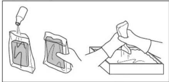
natural_image
Three-step illustration showing a dropper pouring liquid into a bag, a close-up of a container with liquid, and a hand holding a cloth over a tray (no text or symbols)Filter od filca
- Pažljivo kucnite filcani filter o dlan ili ga očistite komprimovanim vazduhom.

OPREZ: Nemojte da čiste filcani filter vodom. Voda može da ošteti filcani filter.
Filter za gorivo
Ako oslabi dovod goriva u motor, uverite se da nije došlo do začepljenja na poklopcu rezervoara za gorivo i na filteru za gorivo (A).
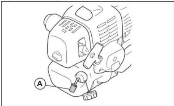
natural_image
Line drawing of a mechanical device with a labeled component (A) and no visible text or symbolsNanošenje maziva u menjač ugla
natural_image
Technical line drawing of a mechanical assembly with a lever and pivot point (no text or symbols)Pregled svećice

OPREZ: Uvek koristite preporučeni tip svećice. Neodgovarajući tip svećice može da ošeteti proizvod.
- Pregledajte svećicu ako je snaga motora mala, ako se teško pokreće ili nepravilno radi u praznom hodu.
- Da biste smanjili rizik od nakupljanja neželjenog materijala na elektrodama svećice, poštujte sledeća uputstva:
a) Uverite se da je broj obrtaja na praznom hodu pravilno podešen. b) Uverite se da je mešavina dobro napravljena. c) Uverite se da je filter za vazduh čist.
- Ako je svećica prljava, očistite je i ujedno proverite da li je razmak između elektroda tačan, pogledajte Tehnički podaci na stranici 183.
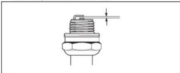
natural_image
Technical line drawing of a mechanical component with threaded body and shaft (no text or symbols)- Zamenite svećicu ako je potrebno.
Oštrenje noževa za košenje trave i listova za košenje trave
- Podjednako naoštrite sve ivice noževa za košenje trave i listova za košenje trave kako bi se održala ravnoteža. Koristite pljosnatu turpiju sa jednostrukim rezom.
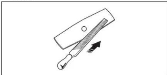
natural_image
Simple line drawing of a tool with a handle and arrow indicating direction (no text or symbols)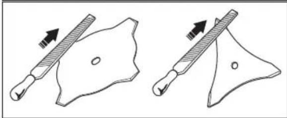
natural_image
Two diagrams showing a tool interacting with a shield-like object, one with an arrow indicating direction (no text or symbols present)Rešavanje problema
Rešavanje problema
| Pokretanje nije uspelo | ||
| Provera Mogući | uzrok Rešenje | |
| Dugme za zaustavljanje | Položaj zaus-tavljanja | Postavite prekidač za zaustavljanje u položaj za pokretanje. |
| Startne kopče Zapinjači koji zapinju | Podesite ili zamenite zapinjače. | |
| Očistite oko zapinjača. | ||
| Obratite se ovlašćenom servisnom centru. | ||
| Rezervoar za gorivo | Neispravni tip goriva. | Ispraznite rezervoar i koristite ispravno gorivo. |
| Karburator Podešavanje brzine praznog hoda. | Prilagodite brzinu praznog hoda pomoću T-zavrtnja. | |
| Varničenje (nema varnica) | Svećica je za-mašćena ili mokra. | Postarajte se da svećica bude suva i čista. |
| Zazor svećice je pogrešan. | Očistite svećicu. Proverite da li je ispravan zazor elektrode. Postarajte se da svećica ima prigušivač. | |
| Informacije o tačnom rastojanju elektroda potražite u tehničkim podacima. | ||
| Svećica Svećica je lab-avo postavlje-na. | Zategnite svećicu. | |
| Filter za gorivo Filter za gorivo je zapušen. | Zamenite filter za gorivo. | |
| Motor se pokreće ali ne nastavlja da radi | ||
| Provera Mogući | uzrok Rešenje | |
| Rezervoar za gorivo | Neispravni tip goriva. | Ispraznite rezervoar i koristite ispravno gorivo. |
| Karburator Motor | ne radi ispravno u praznom hodu. | Obratite se dileru. |
| Filter za vazduh | Filter za vazduh je zapušen. | Očistite filter za vazduh. |
| Filter za gorivo | Filter za gorivo je zapušen. | Zamenite filter za gorivo. |
2020-12-22