
RMO-S591 - Data Storage Unit SONY - Free user manual and instructions
Find the device manual for free RMO-S591 SONY in PDF.

| Product Type | Magneto-optical data storage unit |
| Brand | SONY |
| Model | RMO-S591 |
| Maximum Capacity | 2.6 GB (1024 bytes/sector) per disc |
| Interface | SCSI-2 (Small Computer System Interface-2) |
| Rotation Speed | 3,600 rpm |
| Average Seek Time | 25 ms (typical) |
| Continuous Transfer Rate | 2.03 - 4.06 MB/s (max, 1024 bytes/sector) |
| Cache Memory | 1 MB (S591-DW model) |
| Error Correction | ECC (error rate 10^-12) |
| Compatible Discs | Sony 5.25-inch magneto-optical discs (DOM, EDM, CWO) |
| Power Supply | 100-240 V AC, 50/60 Hz |
| Power Consumption | 0.60 - 0.35 A max |
| Dimensions (W x H x D) | 211 x 70 x 293 mm (without protrusions) |
| Weight | 5.1 kg |
| Operating Temperature | 5 to 40 °C |
| Operating Humidity | 10 to 85% (non-condensing) |
| Cleaning | Use MOA-D51 cleaning kit (sold separately) |
| Emergency Eject | Ejection tool provided |
| Data Security | Write-protect DATA PROTECT slider |
Frequently Asked Questions - RMO-S591 SONY
User questions about RMO-S591 SONY
0 question about this device. Answer the ones you know or ask your own.
Ask a new question about this device
Download the instructions for your Data Storage Unit in PDF format for free! Find your manual RMO-S591 - SONY and take your electronic device back in hand. On this page are published all the documents necessary for the use of your device. RMO-S591 by SONY.
USER MANUAL RMO-S591 SONY
natural_image
Abstract geometric design with diagonal stripes and a triangular shape (no text or symbols)User's Guide
Mode d'emploi
Bedienungsanleitung
Guía del usuario
natural_image
Abstract geometric design with diagonal stripes and a triangular shape divided by a vertical line (no text or symbols)Safety Regulations
Owner's Record
The model and serial numbers are located on the bottom of the unit. Record the serial number in the space provided below.
Refer to them whenever you call upon your Sony dealer regarding this product.
Model No. RMO-S594-DW, RMO-S591-DW Serial No.
Information
For the customer in the U.S.A.
You are cautioned that any changes or modifications not expressly approved in this manual could void your authority to operate this equipment.
This equipment has been tested and found to comply with the limits for a Class B digital device, pursuant to Part 15 of the FCC Rules.
These limits are designed to provide reasonable protection against harmful interference in a residential installation. This equipment generates, uses, and can radiate radio frequency energy and, if not installed and used in accordance with the instructions, may cause harmful interference to radio communications. However, there is no guarantee that interference will not occur in a particular installation. If this equipment does cause harmful interference to radio or television reception, which can be determined by turning the equipment off and on, the user is encouraged to try to correct the interference by one or more of the following measures:
–Reorient or relocate the receiving antenna.
–Increase the separation between the equipment and receiver.
- Connect the equipment into an outlet on a circuit different from that to which the receiver is connected.
- Consult the dealer or an experienced radio/TV technician for help.
This device requires shielded interface cables to comply with FCC emission limits.
WARNING
To prevent fire or shock hazard, do not expose the unit to rain or moisture.
To avoid electrical shock, do not open the cabinet. Refer servicing to qualified personnel only.
CAUTION
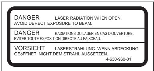
As the laser beam used in the RMO-S594-DW/S591-DW is harmful to the eyes, do not attempt to disassemble the unit.
Refer servicing to qualified personnel only.
This label is affixed inside the unit.
CAUTION:
TO PREVENT ELECTRIC SHOCK, DO NOT USE THIS POLARIZED AC PLUG WITH AN EXTENSION CORD, RECEPTACLE OR OTHER OUTLET UNLESS THE BLADES CAN BE FULLY INSERTED TO PREVENT BLADE EXPOSURE.
This MO disk unit is classified as a CLASS 1 LASER PRODUCT.
The CLASS 1 LASER PRODUCT label is located on the bottom exterior.
CLASS 1
LASER PRODUCT
LASER KLASSE 1
PRODUKT 4-627-223-01
NOTICE
Use the power cord set approved by the appropriate testing organization for the specific countries where this unit is to be used.
LUOKAN 1 LASERLAITE KLASS 1 LASER APPARAT
VAROITUS!
Location and Function of Parts ...... 7
| Front Panel | 7 |
| Rear Panel | 8 |
Chapter 2 Getting Started
Component and Accessory Check List .. 9
Connecting the Disk Unit 10
Setting the SCSI ID.... 11
Setting the Disk Unit's Functions ...... 11
Chapter 3 Using the Disk Unit
Inserting a Disk Cartridge 13
Ejecting a Disk Cartridge.... 14
Chapter 4 Precautions
On the Disk Unit 15
| Safety Considerations | 15 |
| Damage Prevention | 15 |
| Other Points Requiring Attention | 16 |
On the Disk Cartridges 16
Protecting Your Data 17
Cleaning 17
Cleaning a Disk 17
Appendix
Specifications 18
| Disk Unit | 18 |
| Optional Accessories | 19 |
Using this Guide
This guide covers the use and operation of the RMO-S594-DW/S591-DW Magneto-Optical Disk Unit (called the “disk unit” thereafter). Do not attempt to use the disk unit without first carefully reading this guide. When finished, keep it handy for future reference.
The guide is divided into the following sections.
Chapter 1 Introduction
This chapter contains a general overview of the RMO-S594-DW/S591-DW disk unit, touching upon its features, system configuration, and the location and function of its parts.
Chapter 2 Getting Started
This chapter explains how to connect the disk unit to the host computer and other SCSI peripheral devices. It also explains how to set the disk unit's functions and the SCSI ID. Refer to this chapter when setting up the disk unit.
Chapter 3 Using the Disk Unit
In this chapter, you learn how to turn on the disk unit, and how to insert and eject a disk cartridge. Refer to this chapter when you are ready to actually begin using the disk unit.
Chapter 4 Precautions
This chapter contains precautions regarding the use and operation of the disk unit and magneto-optical disk cartridges.
It also discusses cleaning of disks.
Be sure to refer to this chapter before using the disk unit.
Appendix
The Appendix contains an explanation of the disk unit's main specifications.
Notes:
- The manufacturer disclaims all responsibility for any losses incurred through malfunction or use of this product.
- The manufacturer does not warrant the security of data stored using this product. To guard accidental data loss, frequent backup of important data is highly recommended.
- Reproduction of the contents of this manual, in whole or in part, is prohibited.
Chapter 1 Introduction
Overview
Features
The RMO-S594-DW/S591-DW Magneto-Optical Disk Unit has the following features:
- Magneto-optical technology enables repeated writing and erasing of data on the disk.
- The disk unit automatically senses the type of disk being inserted, enabling the free use of both 650-Mbytes (594-Mbytes), 1.3-Gbytes (1.2-Gbytes) and 2.6 Gbytes (2.3 Gbytes) disks indifferently.
- Direct-Overwrite MO disks can be used. The writing performance of this disk unit is 1.5 to 2.0 times faster than that of the earlier MO Disk Unit.
- A maximum of 2.6 Gbytes (1,024 bytes/sector) or 2.3 Gbytes (512 bytes/sector) of data can be written on the two sides of a 5.25-inch magneto-optical disk. This is equivalent to about 1600–1800 times the capacity of a conventional 3.5-inch floppy disk (2HD).
-
Any disk conforming to the internationally accepted CCS (continuous/composite servo) or CCW (continuous composite write-once) format can be used in this disk unit.
-
This disk unit employs SCSI-2 (Small Computer System Interface-2).
- The 3,600min^-1 (3,600 rpm) high-speed spindle motor enables data transfer rates of 2.03 - 4.06 Mbytes/s (1,024 bytes/sector) or 1.78 - 3.56 Mbytes/s (512 bytes/sector).
- The low-profile, light-weight optical pick-up yields average seek times of 25ms.
- Use of a highly reliable error correction code (ECC) system keeps the error rate as low as 10^-12 .
- Optimum operation environment is provided through use of a large, 4MB(S594-DW)/1MB(S591-DW) buffer and optimized cache control algorithm. (Write cache can be enabled or disabled. For details, see “Setting the Disk Unit’s Functions” on page 11.)
Compatible Disks
The RMO-S594-DW/S591-DW can use the following Sony 5.25-inch MO Disks:
| Standard | Sector format | Type* | Capacity | Sony equivalent |
| ISO/IEC CD 14517 | 1024 bytes/sector | R/W(DW) | Approx. 2.6 G bytes | DOM-2600B |
| ISO/IEC CD 14517 | 512 bytes/sector | R/W(DW) | Approx. 2.3 G bytes | DOM-2300B |
| ISO/IEC CD 14517 | 1024 bytes/sector | R/W | About 2.6 G bytes | EDM-2600B |
| ISO/IEC CD 14517 | 512 bytes/sector | R/W | About 2.3 G bytes | EDM-2300B |
| ISO/IEC 13549 | 1024 bytes/sector | R/W | About 1.3 G bytes | EDM-1300B |
| ISO/IEC 13549 | 512 bytes/sector | R/W | About 1.2 G bytes | EDM-1200B |
| ISO/IEC 10089 | 1024 bytes/sector | R | About 650 M bytes | EDM-650B |
| ISO/IEC 10089 | 512 bytes/sector | R | About 600 M bytes | EDM-600B |
| ISO/IEC CD 14517 | 1024 bytes/sector | WO | About 2.6 G bytes | CWO-2600B |
| ISO/IEC CD 14517 | 512 bytes/sector | WO | About 2.3 G bytes | CWO-2300B |
| ISO/IEC 13549 | 1024 bytes/sector | WO | About 1.3 G bytes | CWO-1300B |
| ISO/IEC 13549 | 512 bytes/sector | WO | About 1.2 G bytes | CWO-1200B |
| ISO/IEC 11560 | 1024 bytes/sector | R | About 650 M bytes | CWO-650B |
| ISO/IEC 11560 | 512 bytes/sector | R | About 600 M bytes | CWO-600B |
*R/W(DW):Rewritable(Direct-Overwrite MO), R/W:Rewritable(MO), WO:Write Once, R:Read Only
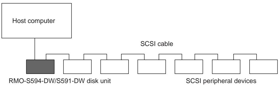
System Configuration
The disk unit should be used with a host computer equipped with SCSI.
A maximum of seven peripheral devices can be linked in a daisy chain on the SCSI bus, and controlled with SCSI-2 commands.
flowchart
graph TD
    A["Host computer"] --> B["RMO-S594-DW/S591-DW disk unit"]
    A --> C["SCSI cable"]
    C --> D["SCSI peripheral devices"]
Fig. 1-1: System Configuration Example
Location and Function of Parts
Front Panel
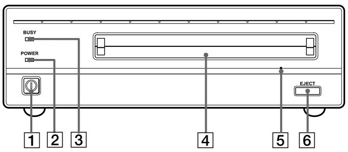
Fig. 1-2: Front View
1 POWER switch
Push the button to turn the power on and off. The power is on when the button is in the depressed position, and off when fully protruding.
2 POWER indicator
The green lamp lights up when the power is turned on.
3 BUSY indicator
As this disk is inserted and the drive becomes ready for read/write operation, the BUSY indicator turns green. The orange lamp lights up when the disk unit is accessing or writing data. This lamp flashes on and off at about 2-second intervals when the unit overheats, regardless of whether or not a disk is being accessed.
4 Disk insertion slot
Insert the disk cartridge into this slot. Refer to the section “Inserting a Disk Cartridge” on page 13 for more information.
5 Emergency eject hole
If the disk cartridge cannot be ejected using the EJECT button 6 turn off the power and insert the supplied emergency eject tool into this hole to trip the emergency eject mechanism. Refer to the section “What to do if the disk does not eject” on page 14 for further details.
6 EJECT button
Press this button to eject the disk cartridge from the disk unit. The EJECT button is disabled with the function switch or software settings prohibit ejection. When the write cache is enabled, it may take a few moments (up to 45 seconds) for the disk to eject because data in the cache must first be written to the disk.
Rear Panel
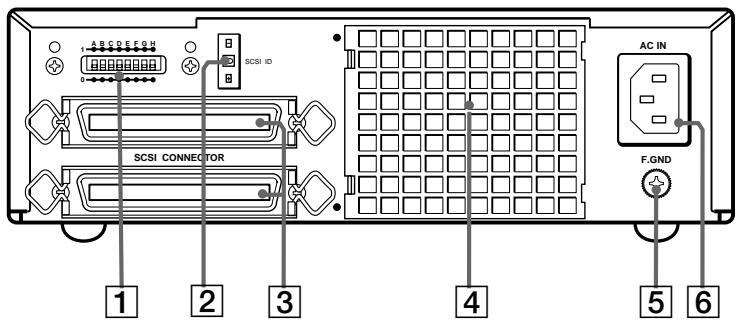
Fig 1-3: Rear View
1 Function switches
Use this switches to set the disk unit's functions in accordance with the host computer and software being used. Refer to the section "Setting the Disk Unit's Functions" on page 11 for more information.
2 SCSI ID switch
Use these switches to set the SCSI ID. Push the “−” button to lower the ID number; push the “+” button to raise the ID number. Refer to the section“Setting the SCSI ID”on page 11 for more information.
3 SCSI connectors
Plug SCSI cables (sold separately) linking the host computer and other SCSI peripherals into these connectors.
Note:
If the disk unit is the last device on the SCSI chain, set function switch F to “1” to turn on the internal terminator. When it is not the last device, make sure that the terminator is off (switch F is set to “0”).
4 Air duct
The air for cooling the disk unit flows through this duct, so be careful not to block its surface or impede the outflow.
5 F.GND (frame ground) terminal
Connect the ground terminals of other devices to the disk unit's frame ground.
6 AC IN (AC power) connector
Connect the supplied AC power cord to this connector.
Chapter 2 Getting Started
Before setting up your RMO-S594-DW/S591-DW Magneto-Optical Disk Unit, check to see that you have all the required components and accessories. Then, connect the disk unit to the host computer and any other SCSI peripherals
you may be using. After checking to see that all the connections have been properly made, set the SCSI ID using the SCSI ID switch and the disk unit's functions using the function switches.
Component and Accessory Check List
Upon opening the carton, check to see that you have all of the components and accessories listed below. Contact your dealer immediately if you find any missing or damaged items.
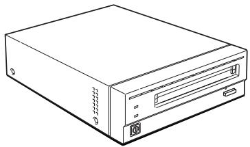
- RMO-S594-DW/S591-DW Magneto-Optical Disk Unit
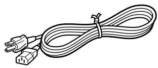
- AC power cord
- Emergency eject tool
- User's Guide
- Guide to Safe Use (Safety Precautions)
natural_image
Line drawing of a desktop computer tower case with drive bays and ventilation slots (no text or labels)RMO-S594-DW/S591-DW Magneto-Optical Disk Unit
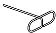
Emergency eject tool
natural_image
Line drawing of a cable with two connectors and a terminal connector (no text or symbols)AC Power cord
Fig 2-1: Items in the Package
Connecting the Disk Unit
You can hook up a maximum of seven SCSI peripheral devices to a single host computer through its SCSI bus.
Use either of the following Sony SCSI cable (sold separately) to connect the disk unit.
• MOA-C08 (80 cm, full pitch⇔full pitch)
Notes:
- Before connecting the disk unit, be sure to turn off the disk unit and all other devices on the SCSI chain.
- If the disk unit is the last device on the SCSI chain, set the function switch F on the rear panel to “1” to turn on the internal terminator. When it is not the last device, make sure that the terminator is off (function switch F is set to “0”).
- The total length of the SCSI cables connected to a SCSI chain must not exceed six meters (19 feet 8 1/4 inches).
RMO-S594-DW/S591-DW Magneto-Optical Disk Unit
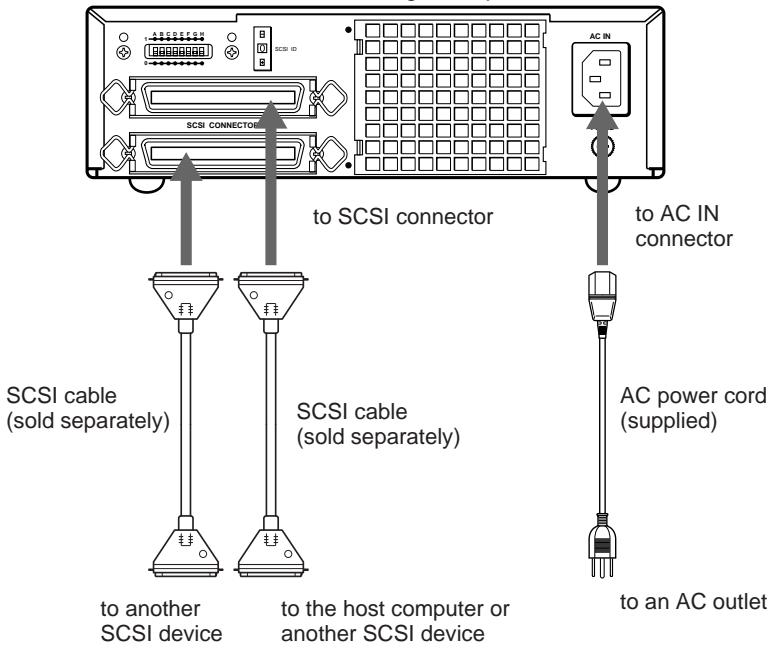
Fig 2-2: Connecting the RMO-S594-DW/S591-DW
Setting the SCSI ID
The factory default setting for the SCSI ID is “0.” If necessary, this ID number can be changed using the SCSI ID switch on the rear panel. Be sure to turn off the power before making any changes.
Pushing the “+” button raises the ID number; pushing the “−” button lowers the ID number.
Notes:
- The disk unit will not operate properly unless the SCSI ID has been set correctly.
- Make sure to select a SCSI ID that has not been assigned to another SCSI device.
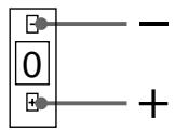
Fig 2-3: SCSI ID Switch
Setting the Disk Unit's Functions
Use function switches (A - H) on the rear panel to select the disk unit's functions in accordance with the host computer and software you are using. Be sure to turn off the power before setting the switches.
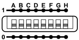
Fig 2-4: Function Switches
This disk unit is equipped with a write cache.
When the write cache is enabled, never turn off the disk unit power without making sure that all data has been written to the disk from cache memory. Data will be lost if you turn off the power before all data in cache memory has been written to the disk.
Before powering off the disk unit, be sure to eject the disk. Ejecting the disk writes data from cache memory to the disk.
Note:
Even though the drive will flush data periodically to the disk, data may be lost in the case of a power failure.
Table 2-1: Function Switch Settings
| Switch | Function | 1 | 0 |
| A | Parity check | SCSI parity check is disabled. | SCSI parity check is enabled. |
| B | Device type | Peripheral device type 00H (Direct Access Device) | Peripheral device type 07H (Optical Memory Device) |
| C | Write cache control | Disable write cache. | Enable write cache. |
| D | Fast SCSI control | Fast SCSI compatible | Not Fast SCSI compatible |
| E | Force verify | All write operations are verified. (with a verify pass) | All write operations are normal operations. (without a verify pass) |
| F | Terminator | The internal terminator is on. | The internal terminator is off. |
| G | Auto spin up | Inserting a disk does not causes the spindle motor to rotate. | Inserting a disk causes the spindle motor to rotate. |
| H | Manual eject | Disk cartridge cannot be ejected by pressing the EJECT button. | Disk cartridge can be ejected by pressing the EJECT button |
: Factory setting
Inserting a Disk Cartridge
Use the following Sony 5.25-inch MO disks in your RMO-S594-DW/S591-DW disk unit.
• DOM-2600B (1,024 bytes/sector, 2.6 Gbytes)
• DOM-2300B (512 bytes/sector, 2.3 Gbytes)
• EDM-2600B (1,024 bytes/sector, 2.6 Gbytes)
• EDM-2300B (512 bytes/sector, 2.3 Gbytes)
• EDM-1300B (1,024 bytes/sector, 1.3 Gbytes)
• EDM-1200B (512 bytes/sector, 1.2 Gbytes)
• CWO-2600B (1,024 bytes/sector, 2.6 Gbytes)
• CWO-2300B (512 bytes/sector, 2.3 Gbytes)
• CWO-1300B (1,024 bytes/sector, 1.3 Gbytes)
• CWO-1200B (512 bytes/sector, 1.2 Gbytes)
1 Press the POWER switch located on the left side of the front panel.
This turns on the disk unit and causes the POWER indicator to light up.
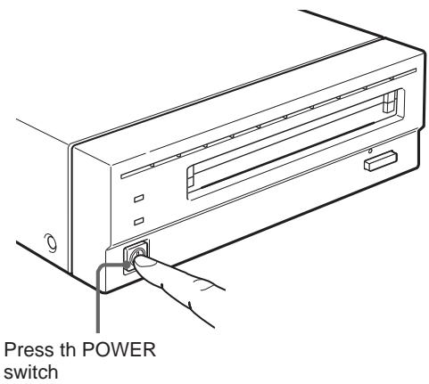
Fig 3-1: Turning on the Disk Unit
2 Start up the host computer. Refer to the manual supplied with the host computer for the start up procedure.
3 Insert a disk cartridge with the side you want to use facing upwards.

Fig 3-2: Inserting a Disk Cartridge
4 Access or write data on the disk using software commands on the host computer. The BUSY indicator lights up while the unit is accessing the disk.
■ What to do if the disk unit stops operating
When the temperature in the disk unit exceeds the preset level, the BUSY indicator starts flashing on and off at about 2-second intervals, regardless of whether or not a disk is being accessed, and the disk unit stops operating.
If this happens, you should improve the ventilation of a setting area.
If the disk unit still refuses to operate, unplug the unit and contact your dealer.
Ejecting a Disk Cartridge
Eject the disk cartridge either by using software commands or by pressing the EJECT button.
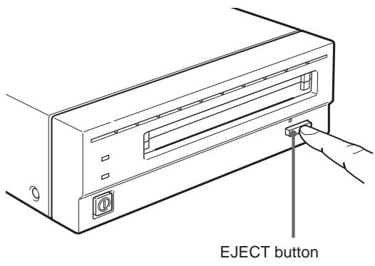
Fig 3-3: Ejecting the Disk Cartridge Using the EJECT button
Note
Do not attempt to eject a disk cartridge while the BUSY indicator is lit orange (except when it is flashing at about 2-second intervals due to overheating). Ejecting the disk while it is being accessed may cause data write errors or may result in loss of data.
Also, it may take a few moments (up to 45 seconds) for the disk to eject when the write cache is enabled, because data in the cache must first be written to the disk.
■ What to do if the disk does not eject
The disk cartridge may not come out, even when you press the EJECT button or use a software command, under the following conditions:
- The eject function has been disabled using the function switch or a software command;
- The host computer is not functioning properly;
- The disk unit has been turned off (due to a power failure, etc.); or
- Something is wrong with your disk unit itself.
When you cannot eject the disk cartridge using the EJECT button or software commands, remove it as follows.
1 Turn off the disk unit if the power is still on.
2 Insert the emergency eject tool (or a paper clip) straight into the emergency eject hole to trip the manual ejection mechanism.
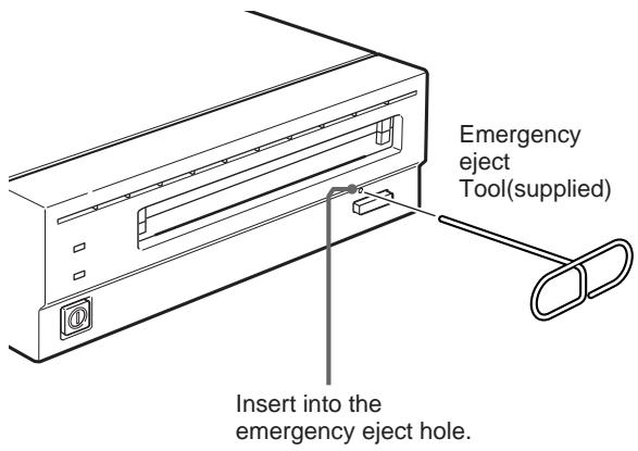
Fig 3-4: Inserting the Emergency Eject Tool
This should cause the disk cartridge to eject.
Caution
The tip of the emergency eject tool is sharp. When handling the tool, please be careful to avoid injury.
On the Disk Unit
Safety Considerations
■ Power supply
- Be sure to use 100 - 240V AC.
- Do not share the AC outlet with any other power-consuming equipment such as copying machines or shredders.
■ AC power cord
- Be careful not to place or drop heavy object on the power cord, or subject it to anything that may damage it.
- When unplugging the cord from an AC outlet, be sure to grasp the plug itself. Pulling on the cord may cause damage to the internal wiring.
- Unplug the unit when not using it for long period of time.
■ Handling the emergency eject tool
The tip of the emergency eject tool is sharp. When handling the tool, please be careful to avoid injury. Do not use the tool for any purpose other than ejecting disks.
Damage Prevention
■ Do not subject the disk unit to shock or vibration
Dropping the unit or subjecting it to strong impact may damage the disk unit.
■ Setting position
The disk unit is designed to be used in the horizontal position. Do not position it at an angle.
■ Location requirements
Careful consideration should be given to the following in selecting a site to install or store your disk unit.
Avoid the following conditions:
• High humidity
- High temperatures
- Direct sunlight
• Dust
- Strong vibration
- Wide temperature fluctuations
Ventilation
Care should be exercised to prevent the internal mechanisms of the disk unit from overheating. Be careful not to clog or block the vent, or place the unit in an area with poor ventilation. The disk unit may stop operating altogether if the internal temperature becomes too high.
Condensation
Avoid subjecting the disk unit to extremes in temperature. If, for example, the disk unit is moved suddenly from a very cold location to a warm one, moisture from condensation may form within the unit due to the quick rise in ambient temperature. If a sudden change in the temperature cannot be avoided, wait for an hour or more before using the disk unit. Inserting a disk cartridge into the mechanism when moisture is present may cause damage to both the disk and the disk unit. Remove the disk cartridge immediately if you suspect any condensation problems. The moisture should evaporate quickly if the disk unit is left on without a disk inserted.
■ Moving the disk unit
Be sure to remove the disk cartridge when the disk unit is not being used. Also never move or transport the unit with the disk cartridge still inserted.
While in operation, the disk rotates at a high speed. Moving the disk unit at such a time may disturb the spinning disk and cause it to be damaged. Always remove the disk cartridge before moving your disk unit.
■ If problems occur
If any problems occur, turn off the power and unplug the disk unit, contact your dealer.
Other Points Requiring Attention
■ Electrical noise
The high-frequency signal generated by the disk unit may cause interference or static on other electrical appliances such as radios, televisions and audio tuners. If this should occur, move the disk unit a little farther away from the affected appliance.
■ Maintenance
Clean the cabinet with a dry soft cloth, or with a soft cloth lightly moistened with a mild detergent solution. Do not use any type of solvent, such as alcohol or benzine, which may damage the finish.
On the Disk Cartridges
- Do not drop the disk cartridge or subject it to any violent shocks or vibration.
- Do not disassemble the disk cartridge. It is a precision component and has been carefully adjusted at the factory prior to shipment.
- Do not open the disk cartridge's shutter manually or touch the disk inside. The shutter is designed to open automatically when the cartridge is inserted into the disk unit.
- Do not use the cartridge under ambient conditions of high humidity or wide temperature fluctuations. Moisture from condensation may make it impossible to read or write data.
- Avoid inserting and ejecting the disk cartridge more than is necessary.
- Always eject and remove the disk cartridge from the disk unit after using it.
■ Storing disk cartridges
- Store the disk cartridges in their cases.
- Do not leave the cartridges exposed to direct sunlight or excessive heat, like on the dashboard or in the glove compartment of an automobile. Do not store the disk cartridges under the following conditions.
– Excessive dust and debris - Exposure to direct sunlight
– Near a heat source
–High humidity
Protecting Your Data
The magneto-optical disk cartridges are equipped with a DATA PROTECT switch (red tab) to prevent accidental erasure of data on the disk or inadvertent writing of unwanted data. Slide this switch in the direction of the arrow as illustrated below to enable the write protect function.
You can still read the data contained on the disk, but will not be allowed to write on or erase the disk. Return the switch to its original position to disable the write protect.
Make it a practice to leave the write protection enabled when you do not foresee the need to write on the disk.
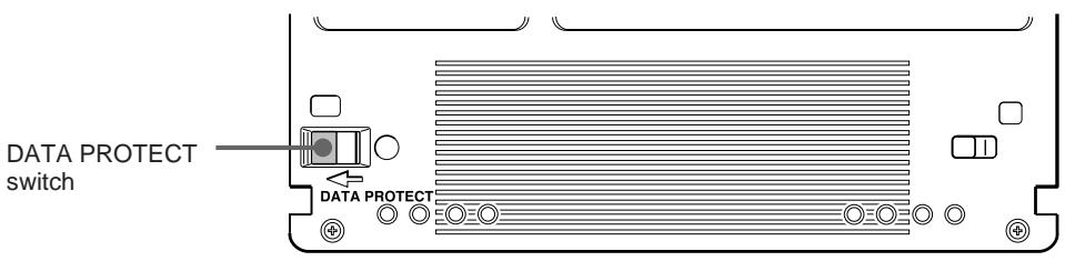
Fig 4-1: Write Inhibit Position
Cleaning
Cleaning a Disk
Dust and stains may accumulate on MO disks when they are used for a long period of time. To avoid resultant data read/write errors, use an optional disk cleaner. To maintain the high performance and prolong the useful life of your MO disk, cleaning at least once every three months is recommended.
■ Disk cleaning accessories
Use the following Sony disk cleaning kit or disk cleaner (sold separately).
• MOA-D51 Disk Cleaning Kit Do not use any other type of disk cleaner as it may cause data read/write errors due to the differences in disk surface characteristics. For cleaning instructions, refer to the manual supplied with each cleaning accessory
Attention:
In the disk unit, preventive measures are taken to guard against dust. It is unnecessary to clean the optical lens of your disk unit. Using a lens cleaning cartridge may damage the disk unit.
Specifications
Disk Unit
Performance
Capacity (formatted)
Per disk
2.6 Gbytes (ZCAV 1,024 bytes/sector)
2.3 Gbytes (ZCAV 512 bytes/sector)
1.3 Gbytes (ZCAV 1,024 bytes/sector)
1.2 Gbytes (ZCAV 512 bytes/sector)
Per side
1.3 Gbytes (ZCAV 1,024 bytes/sector)
1.15 Gbytes (ZCAV 512 bytes/sector)
652.3 Mbytes (ZCAV 1,024 bytes/sector)
595.6 Mbytes (ZCAV 512 bytes/sector)
Rotation speed
3,600 min ^-1 (3,600 rpm)
User data transfer rate
Continuous transfer rate
2.03 - 4.06 Mbytes/s
(maximum, 1,024 bytes/sector)
1.78 - 3.56 Mbytes/s
(maximum, 512 bytes/sector)
Burst transfer rate
maximum 5Mbytes/s (synchronous)
Host interface
SCSI-2 (Small Computer System Interface-2)
ANSI X3.131–1994
■ Operating environment
Installation
Horizontal (±5°)
Temperature
Operating
5^ to 40^(41^ to 104^)
(gradient 10°C/h or 18°F/h)
Non-operating
-30^ to 60^(-22^ to 140^)
Relative humidity
Operating
10 % to 85 % (no condensation)
Non-operating
10 % to 90 %
Laser
Type
Semiconductor AlGaInP laser
Wavelength
685 nm ± 10 nm
Maximum output
30 mW
■ Power supply and others
Power supply
100 - 240 V AC ±10%, 50/60 Hz ±5%
Current drain
0.60 - 0.35 A max
Maximum external dimensions (excluding
protruding parts and air duct)
211 x 70 x 293 mm (W/H/D)
(8 3/8 x 2 7/8 x 11 5/8 inches)
Weight
5.1 kg (11.3 lb.)
Accessories
AC power cord (1)
Emergency eject tool(1)
User's Guide (1)
Design and specifications are subject to change without notice.
Optional Accessories
Direct Overwrite MO disks
DOM-2600B (1,024 bytes/sector, 2.6 Gbytes)
DOM-2300B (512 bytes/sector, 2.3 Gbytes)
MO disks
EDM-2600B (1,024 bytes/sector, 2.6 Gbytes)
EDM-2300B (512 bytes/sector, 2.3 Gbytes)
EDM-1300B (1,024 bytes/sector, 1.3Gbytes)
EDM-1200B (512 bytes/sector, 1.2 Gbytes)
Continuous composite write-once disks
CWO-2600B (1,024 bytes/sector, 2.6 Gbytes)
CWO-2300B (512 bytes/sector, 2.3 Gbytes)
CWO-1300B (1,024 bytes/sector, 1.3 Gbytes)
CWO-1200B (512 bytes/sector, 1.2 Gbytes)
SCSI cables
MOA-C08 (80 cm, full pitch full pitch)
MOA-D51 Disk Cleaning Kit
Règles de sécurité
NOTICE
natural_image
Line drawing of a beige internal computer drive (no text or symbols)natural_image
Line drawing of a coiled electrical plug with two connectors (no text or symbols)natural_image
Line drawing of a desktop computer case with drive bays and ports (no text or symbols)natural_image
Line drawing of a coiled electrical plug with two connectors (no text or symbols)- Safety Regulations
- Owner's Record
- Information
- WARNING
- CAUTION
- CAUTION:
- NOTICE
- LUOKAN 1 LASERLAITE KLASS 1 LASER APPARAT
- VAROITUS!
- Chapter 2 Getting Started
- Chapter 3 Using the Disk Unit
- Chapter 4 Precautions
- Appendix
- Using this Guide
- Chapter 1 Introduction
- Notes:
- Overview
- Features
- Compatible Disks
- System Configuration
- Location and Function of Parts
- Front Panel
- POWER switch
- POWER indicator
- BUSY indicator
- Disk insertion slot
- Emergency eject hole
- EJECT button
- Rear Panel
- Function switches
- SCSI ID switch
- SCSI connectors
- Note:
- Air duct
- F.GND (frame ground) terminal
- AC IN (AC power) connector
- Component and Accessory Check List
- Connecting the Disk Unit
- Setting the SCSI ID
- Setting the Disk Unit's Functions
- Inserting a Disk Cartridge
- ■ What to do if the disk unit stops operating
- Ejecting a Disk Cartridge
- Note
- ■ What to do if the disk does not eject
- On the Disk Unit
- Safety Considerations
- ■ Power supply
- ■ AC power cord
- ■ Handling the emergency eject tool
- Damage Prevention
- ■ Do not subject the disk unit to shock or vibration
- ■ Setting position
- ■ Location requirements
- Ventilation
- Condensation
- ■ Moving the disk unit
- ■ If problems occur
- Other Points Requiring Attention
- ■ Electrical noise
- ■ Maintenance
- On the Disk Cartridges
- ■ Storing disk cartridges
- Protecting Your Data
- Cleaning
- Cleaning a Disk
- ■ Disk cleaning accessories
- Attention:
- Specifications
- Disk Unit
- Performance
- ■ Operating environment
- Laser
- ■ Power supply and others
- Optional Accessories
- Règles de sécurité
Brand : SONY
Model : RMO-S591
Category : Data Storage Unit