
FGIM5151 - Ice Maker VIKING - Free user manual and instructions
Find the device manual for free FGIM5151 VIKING in PDF.

| Product Type | Built-in/ Freestanding Ice Maker |
| Brand | Viking |
| Model | FGIM5151 |
| Total Width | 37.8 cm (14-7/8 in) |
| Total Height | 86.0 to 88.6 cm (33-7/8 to 34-7/8 in) |
| Depth (without door panel) | 55.9 cm (22 in) |
| Depth (with door panel) | 57.8 cm (22-3/4 in) |
| Depth (with handle) | 64.1 cm (25-1/4 in) |
| Net Weight | 51.25 kg (113 lb) |
| Electrical Supply | 115 V, 60 Hz, 15 A, dedicated circuit |
| Max. Power Consumption | 5 A |
| Water Supply | Copper tubing 6 mm (1/4 in) OD, pressure 20-80 psi, temperature 5-38 °C (40-100 °F) |
| Drain (pump model) | Plastic hose 9.5 mm (3/8 in) ID |
| Drain (gravity model) | Tubing 16 mm (5/8 in) ID x 22 mm (7/8 in) OD |
| Ice Storage Capacity | 11.8 kg (26 lb) |
| Door Reversibility | Yes, left or right hinges (components included) |
| Custom Panel | Compatible, max. weight 6.8 kg (15 lb), thickness 14.5-19 mm (5/8-3/4 in) |
| Adjustable Feet | Yes, 4 leveling legs |
| Plug Type | GFCI mandatory if required locally (standard circuit breaker not recommended) |
| Child Safety | Remove doors before disposal |
| Water Filter | Recommended (not included) |
| Maintenance | Clean filters and storage bin regularly |
| After-Sales Service | Authorized Viking service center, approved parts required |
Frequently Asked Questions - FGIM5151 VIKING
User questions about FGIM5151 VIKING
0 question about this device. Answer the ones you know or ask your own.
Ask a new question about this device
Download the instructions for your Ice Maker in PDF format for free! Find your manual FGIM5151 - VIKING and take your electronic device back in hand. On this page are published all the documents necessary for the use of your device. FGIM5151 by VIKING.
USER MANUAL FGIM5151 VIKING
natural_image
Exterior view of a modern office building (no signage)5 SERIES
15"W. Undercounter/Freestanding
Ice Machine
FGIM5151
FPIM5151
TABLE OF CONTENTS
Warnings & Important Safety Instructions 3
Dimensions (Professional) 5
Dimensions (Custom Panel) 6
Specifications 7
Cutout Dimensions 7
Drain/Electrical Locations 8
General Information 9
Air Flow 9
Filters and Treatment 9
Installation Overview 10
Accessory Door Panel 10
Custom Panel 10
Door Panel Attachment 12
Door Swing Change 13
Water and Drain Installation 14
Electrical Connection 16
Final Installation 16
Installation Checklist 16
Service Information 17
IMPORTANT – PLEASE READ AND FOLLOW
- Before beginning, please read these instructions completely and carefully.
- DO NOT remove permanently affixed labels, warnings, or plates from the product. This may void the warranty.
- Please observe all local and national codes and ordinances.
- Please ensure that this product is properly grounded.
- The installer should leave these instructions with the consumer who should retain for local inspector's use and for future reference.
A GFI shall be used if required by NFPA-70 (National Electric Code), federal/state/local laws, or local ordinances.
- The required use of a GFI is normally related to the location of a receptacle with respect to any significant sources of water or moisture.
- Viking Range Corporation will NOT warranty any problems resulting from GFI outlets which are not installed properly or do not meet the requirements below.
If the use of a GFI is required, it should be:
- Of the receptacle type (breaker type or portable type NOT recommended)
• Used with permanent wiring only (temporary or portable wiring NOT recommended) - On a dedicated circuit (no other receptacles, switches or loads in the circuit)
- Connected to a standard breaker of appropriate size (GFI breaker of the same size NOT recommended)
- Rated for Class A (5 mA +/- 1 mA trip current) as per UL 943 standard)
- In good condition and free from any loose-fitting gaskets (if applicable in outdoor situations)
- Protected from moisture (water, steam, high humidity) as much as reasonably possible
WARNING
To reduce the risk of fire, electric shock, or injury when using your unit, follow these basic precautions:
- Read all instructions before using the unit.
- Never allow children to operate, play with, or crawl inside the unit.
- Never clean unit parts with flammable fluids. The fumes can create a fire hazard or explosion.
- Always turn the power on/off switch (located behind the air grille on top right side) to the OFF position before attempting to change light bulbs, clean, or service the unit.
FOR YOUR SAFETY
DO NOT STORE OR USE GASOLINE OR OTHER FLAMMABLE VAPORS AND LIQUIDS IN THE VICINITY OF THIS OR ANY OTHER APPLIANCE. THE FUMES CAN CREATE A FIRE HAZARD OR EXPLOSION.
It is your responsibility to be sure your ice machine is:
- located so the front is not blocked to restrict incoming or discharge air flow.
• properly leveled. - located in a well ventilated area.
- connected to the proper kind of outlet, with the correct electric supply and grounding. A 115V, 60 Hz, 15 amp fused electrical supply is required. Note: Time delay fuse or circuit breaker is recommended.
- not used by anyone unable to operate it properly.
• used only for its intended purpose.
• properly maintained.
•SAVE THESE INSTRUCTIONS•
PROPER DISPOSAL (OF OLD REFRIGERATION UNIT)

DANGER
RISK OF CHILD ENTRAPMENT
Before You Throw Away Your Old Refrigeration Unit:
• Take off the doors.
- Leave the shelves in place so that children may not easily climb inside.
IMPORTANT: Child entrapment and suffocation are not problems of the past. Junked or abandoned refrigeration units are still dangerous... even if they will sit for "just a few days."
IMPORTANT:
Now that you have a new ice machine, it is extremely important that you dispose of your old appliance in a way that minimizes the possibility that children will find it. There have been many cases in years past of children crawling inside junked and abandoned refrigeration units and becoming trapped or suffocated.
Contact your municipal waste disposal authority to find out the best and safest way to dispose of your old refrigeration unit.
natural_image
Line drawing of a single refrigerator with open lid and ventilation grilles (no text or symbols)DIMENSIONS (PROFESSIONAL)
Dimensions
FGIM/FPIM
w/ Professional
door panel
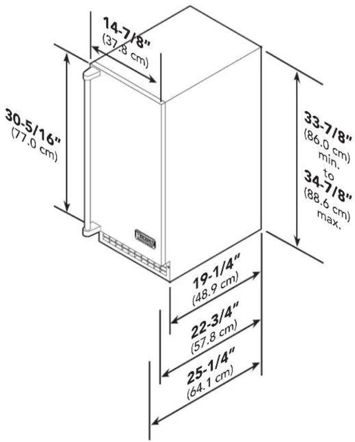
Door Swing

DIMENSIONS (CUSTOM PANEL)
Dimensions FGIM/FPIM w/ Custom door panel
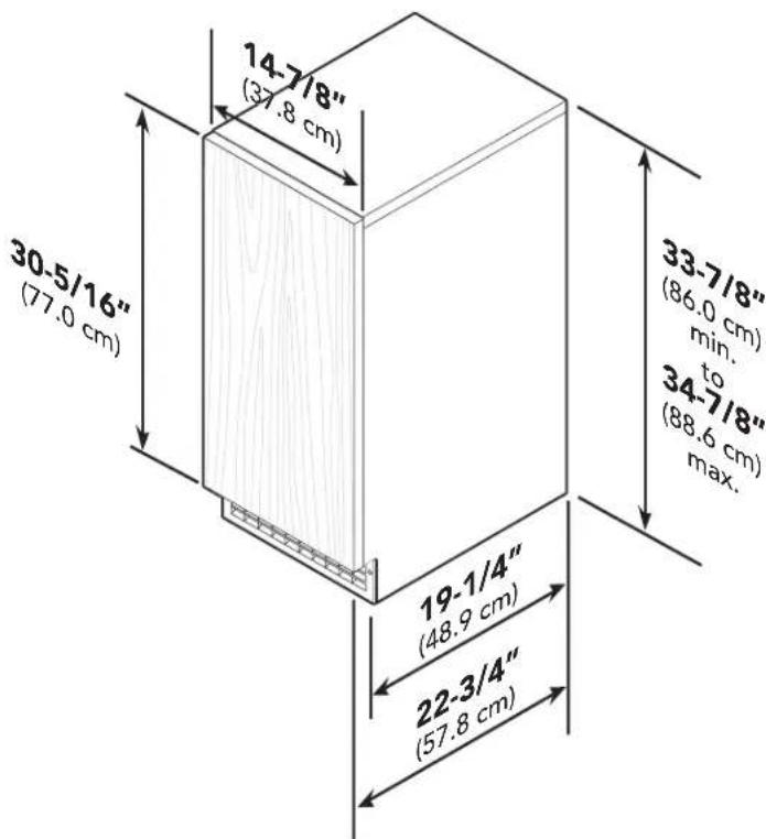
Door Swing
SPECIFICATIONS
| 15"W. Undercounter/Freestanding Ice Machine | ||
| Description | FGIM5151 FPIM5151 | |
| Overall width | 14-7/8" (37.8 cm) | |
| Overall height | 33-7/8" (86.0 cm) min. to 34-7/8" (88.6 cm) max. | |
| Overall depth from rear (without door panel) (with door panel) (with door handle) | 22" (55.9 cm)22-3/4" (57.8 cm)25-1/4" (64.1 cm) | |
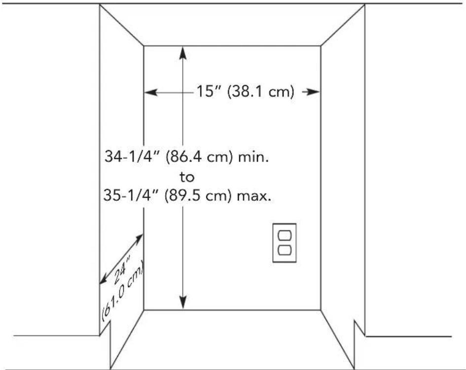
| Cutout width | 15" (38.1 cm) | |
| Cutout height | 34-1/4" (86.4 cm) min. to 35-1/4" (89.5 cm) max. | |
| Cutout depth | 24" (61.0 cm) | |
| Electrical requirements 115V/60 Hz, 15 amp dedicated circuit6' 3-wire cord attached to product | ||
| Maximum amp usage 5.0 amps | ||
| Inlet water requirement | 1/4" OD copper tubing inlet waterline20 psi min. to 80 psi max.40°F (5°C) min. to 100°F (38°C) max. | |
| Drain requirements | 5/8" ID x 7/8" OD plastic tubing required 3/8" ID x 10' plastic tubing supplied | |
| Temperature requirements 50°F (10°C) min. to 100° (38°C) max. | ||
| Maximum storage capacity | 26 lbs. | |
| Approximate shipping weight | 113 lbs. (51.25 kg) 118 lbs. (53.5 kg) | |
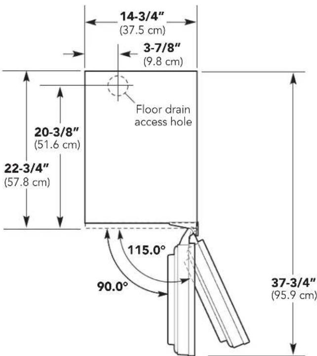
CUTOUT DIMENSIONS
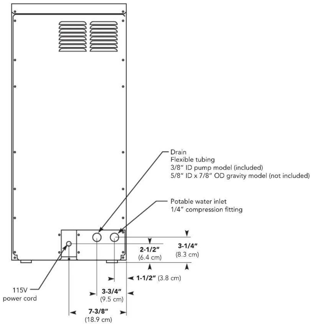
SPECIFICATIONS DRAIN/ELECTRICAL LOCATION
GENERAL INFORMATION
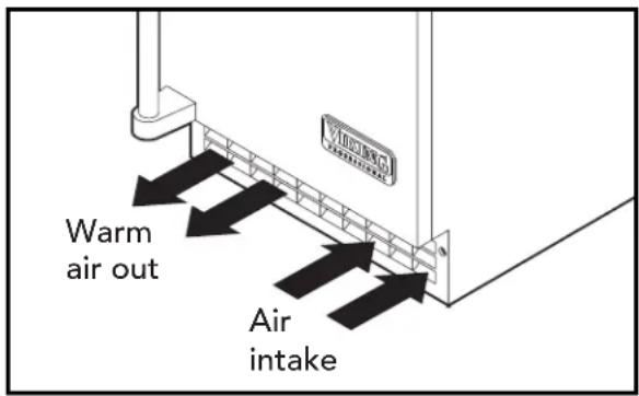
AIR FLOW
The machine takes in room temperature air at the lower right front and forces warm air out the lower left front. Restricting the airflow will adversely affect the ability of the ice machine to make ice.
Filters and Treatment
In general, it is always a good idea to filter the water. A water filter, if it is of the proper type, can remove taste and odors as well as particles. Some methods of water treatment for dissolved solids include reverse osmosis, and polyphosphate feeders.
RO Water
This machine can be supplied with Reverse Osmosis water, but the water conductivity must be no less than 10 microSiemens/cm. A reverse osmosis system should include post treatment to satisfy the R.O. water's potential aggressiveness. Deionized water is not recommended.
Because water softeners exchange one mineral for another, softened water may not improve water conditions when used with ice machines. Where water is very hard, softened water could result in white, mushy cubes that stick together.
If in doubt about the water, contact a local point of use water specialist for recommendations on water treatment.
INSTALLATION OVERVIEW
The ice machine must:
- Be connected to cold, potable water.
- Be connected to a drain.
- Be connected to the proper power supply.
- Be able circulate air through the vents at the front.
Note: DO NOT build in so that the door is recessed. Door is meant to be flush with surrounding cabinetry, but not recessed.
INSTALLATION PARTS
The following installation parts are supplied with the ice machine:
2-Hinge covers 2-Door stop pins 1-Upper door bracket (LH)
2-Hinge side covers 10-#8 sheet metal screws 1-Lower door bracket (LH)
2-Hole plugs 2-8-32 Machine screws 2-Black kickplate screws
2-Hinge opening covers 4-Leveling leg caps 1-Access panel button cover
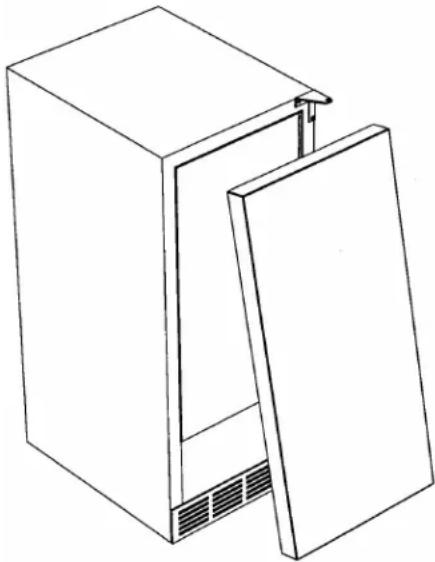
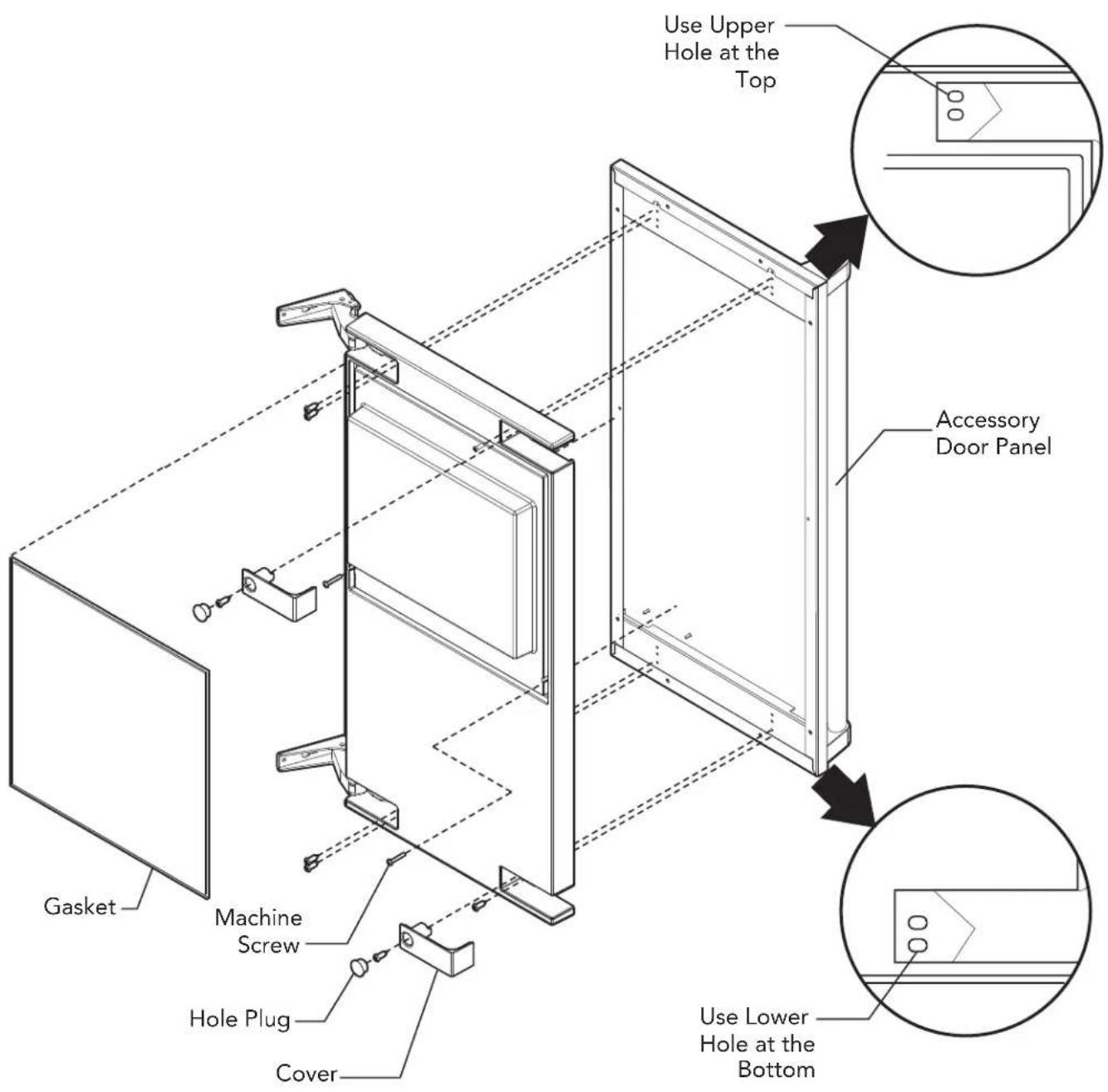
ACCESSORY DOOR PANEL
The ice machine is supplied without a finished door panel. Accessory door panels are offered or a custom panel may be used.
Accessory Door Panel Attachment
Note: If door swing is to be changed, it must be done before panel is attached.
To attach a door panel:
The panel will be held on by 6 screws (supplied with door panel) and 2 machine screws (supplied with ice machine).
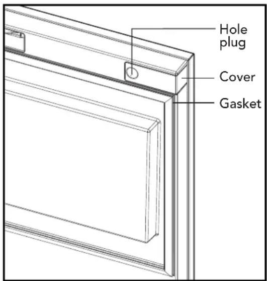
- Remove the gasket and retain for later use.
- If the door panel is stainless steel, remove any plastic covering the stainless steel panel.
- Place the panel onto the outside of the door, and secure it to the door using two machine screws, located at the left center and right center ( - behind door gasket).
- Fasten the panel to the door using the 6 screws (supplied with door panel). In the hinge area, use the outermost screw holes.
- Place the covers over the hinge areas, and secure each cover to the door using a screw (supplied with door panel).
- Insert hole plug over screw installed in step 5 (supplied).
- Return the gasket to its original position.
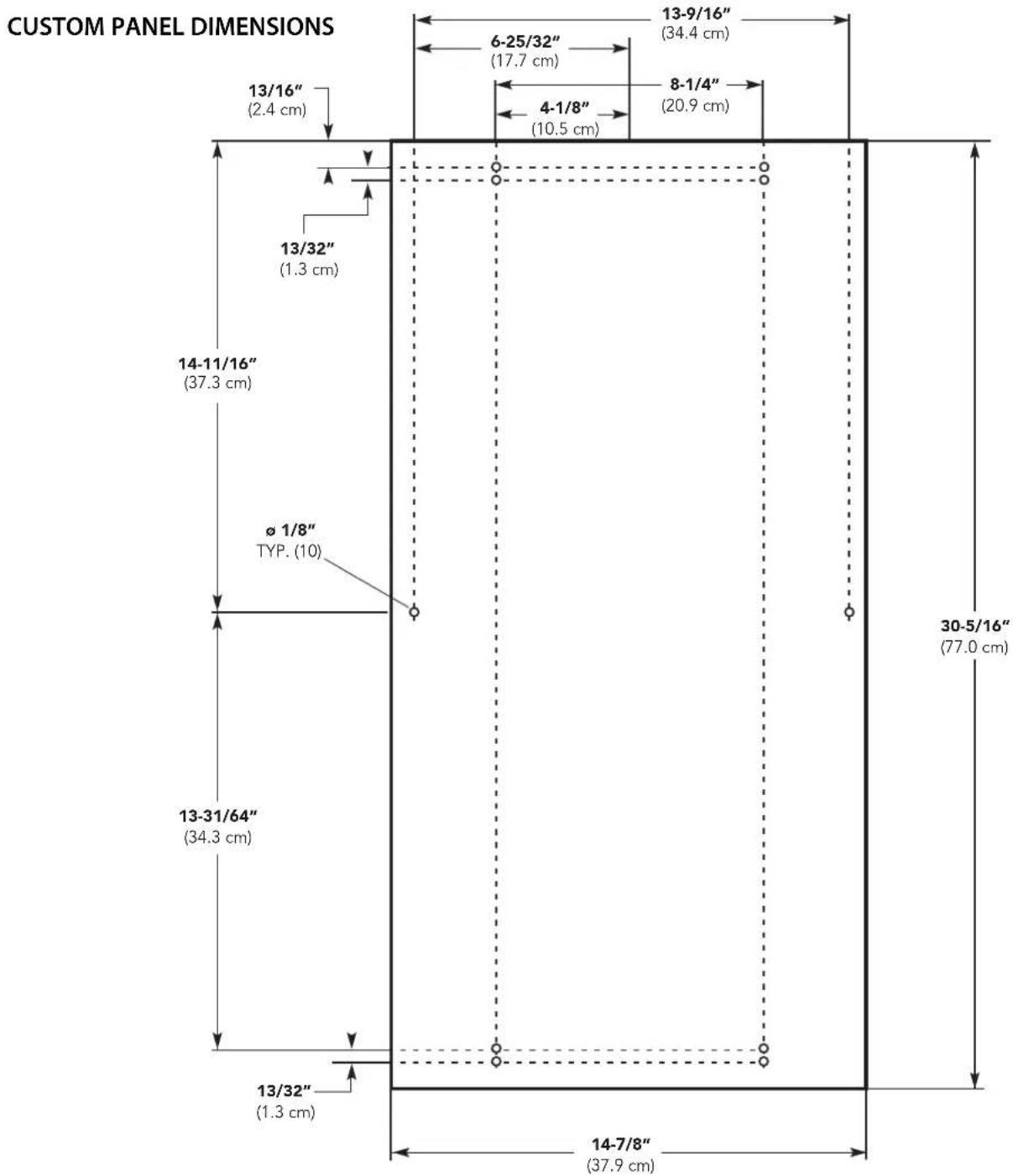
CUSTOM PANEL
A custom panel of wood or other material not exceeding 15 lb can be attached to the door. Attachment is from the ice side of the door. Holes are provided in the door for this purpose.
To create and attach a custom panel:
- Panel width: 14-7/8" (37.9 cm)
- Panel height: 30-5/16" (77.0 cm)
-
Panel thickness: 5/8'' (14.5 cm) to 3/4'' (1.9 cm)
-
Measure overall height of cabinet opening where ice machine will be (floor to bottom of countertop edge).
- Determine desired kickplate space (from bottom of door to floor). This could be equal to the adjacent cabinet's kickplate space or another space the user wants.
- Subtract kickplate space from cabinet opening.
- Subtract 1/8" or more for clearance space between top of door and bottom of countertop edge from cabinet opening. This is the maximum door length.
-
Cut panel to width
-
Cut panel to length (cabinet space - kickplate space - top clearance = length).
- Determine top of panel.
- Mark hole locations using drawing on the back of these instructions. Drawing assumes top of panel will be flush with top of door. Measure hole locations from the top of the panel.
- Drill pilot holes for wood screws. Use drill stop to prevent drilling through the panel.
- Mount panel to door using wood screws or supplied panel mounting screws.
Note: When installed, ice machine must be adjusted for height to position top of door to desired clearance.
other
| Dimension | Width (cm) | | ----------------- | ---------- | | 13/16" (2.4 cm) | | | 6-25/32" (17.7 cm) | | | 8-1/4" (20.9 cm) | | | 13-9/16" (34.4 cm) | | | 4-1/8" (10.5 cm) | | | 13/32" (1.3 cm) | | | 14-11/16" (37.3 cm) | | | Ø 1/8" TYP. (10) | | | 30-5/16" (77.0 cm) | | | 13-31/64" (34.3 cm) | | | 13/32" (1.3 cm) | | | 14-7/8" (37.9 cm) | |DOOR PANEL ATTACHMENT
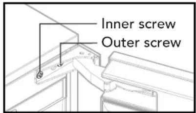
DOOR SWING CHANGE
The door can be attached to open with hinges on the left or right using new brackets shipped loose in the ice bin. Retain all screws for re-use.
To change:
- Remove inner screw holding each hinge to cabinet, loosen the outer screw.
- Slide hinges to the side and remove door from cabinet. Remove outer screws loosened in step 1 from both hinge brackets.
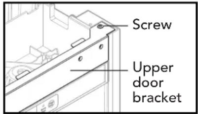
-
Remove two screws securing top panel to back, pull top panel back and remove from cabinet.
-
Remove two screws at the top of the upper door hinge bracket and lift out of the cabinet. Replace with the left hinge upper door bracket. Fasten it to the cabinet using the original screws.
-
Return the top panel to the cabinet and fasten it with the original screws.
-
Remove kickplate and front service panel.
-
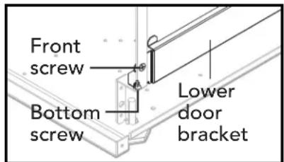
Remove two front screws and two bottom screws holding the lower door hinge bracket to the cabinet. Replace with the left hinge lower door bracket. Secure it using the original screws.
-
Remove the upper hinge and move it to the door's opposite side, bottom location. Secure using the original screws.
-
Remove the original lower hinge and move it to the door's opposite side, upper location. Secure using the original screws. Note: If door panel is attached, it must be removed to access hinge screws.
-
Install a screw removed in step 2 in outer hole of upper and lower door brackets.
-
Attach the door to the cabinet using the original screws.
-
Return kickplate and front service panel to their original positions and attach to the cabinet using the original screws.
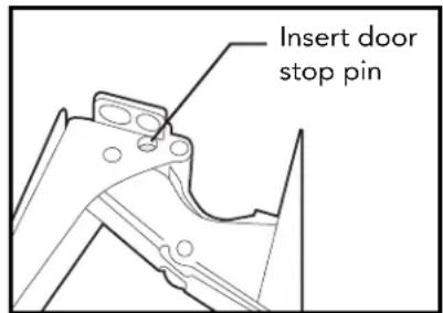
DOOR STOP
- In some situations the door can open too far and damage adjacent cabinets. To prevent that, insert a stop into the provided hole in the top and bottom hinges
- Drive the pin into the hole until the head is against the hinge.
HINGE COVERS
After the hinge pins are installed (if used) and the door panel has been attached, attach the hinge covers.
- Slide the hinge cover over each hinge.
- Attach the side cover over the hinge by peeling off the covering over the adhesive and placing it over the side of the hinge.
Note: If the hinges are used to secure the unit to the cabinet, DO NOT use the side covers.
KICKPLATE
The kickplate is black with a stainless steel covering. To use the stainless steel, no changes are required. To use the black, remove the stainless steel covering by removing the two stainless steel screws. Replace with supplied black screws. DO NOT remove stainless steel covering if ice machine is used outdoors.
INSTALLATION NOTES
Built In Situations: If a finished floor is to be installed in the area after the ice machine has been built in, shims the expected thickness of the floor should be installed under the unit to keep the machine level with the planned floor level.
Installations on a slab: Use a pump model and pump the water to the point of drainage. Pump models will pump 1 story (10 feet) high.
Installations over a crawl space or basement: Either gravity drain or pump model units may be used, if there is not enough room behind the machine for a drain/waste receptacle, the drain will have to be below the floor.
Note: When installed in a corner, the door swing may be limited due to handle contact with the wall or cabinet face.
WATER & DRAIN INSTALLATION
The recommended water supply tubing is 1/4" OD copper. Stainless steel flex or reinforced PVC tube may also be used. Install an easily accessible shut-off valve between the supply and the unit. This shut-off valve should not be installed behind the unit.
Note: DO NOT use self-piercing type valves.
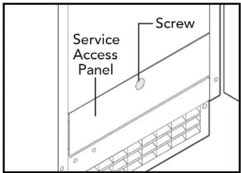
- Remove the front service access panel by removing the screw.
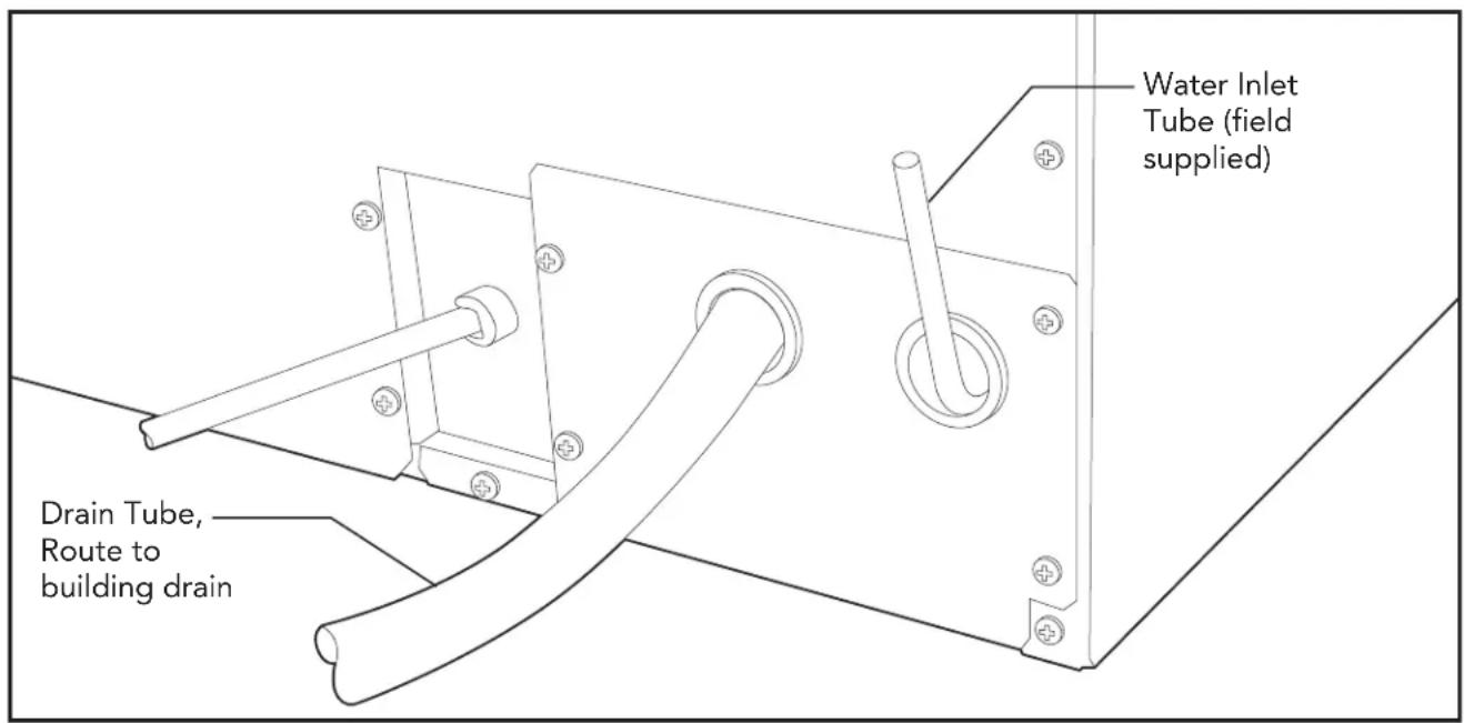
- Route the tubing through the right hole in the back to the inlet water solenoid valve inlet.
- Install a compression fitting on the tubing and connect to the inlet of the solenoid (fitting is located in cloth bag behind access panel).
DRAINS
There are two types of ice machine models, one that drains by gravity and one that has an internal drain pump.
Drain Pump Model drain installation
- Locate the coil of 3/8" ID plastic drain tubing secured to the back of the unit.
- Route the plastic drain tube from the back of the unit to the drain connection point.
IMPORTANT NOTE: Often an air gap is required by local codes between the ice maker drain tube and the drain receptacle.
Back View, Drain Pump Model
CAUTION
Restrictions in the drain system to the machine will cause water to back up into the ice storage bin and melt the ice. Gravity drain tubing must be vented, have no kinks and slope to the building drain. Air gaps are typically required by local code.
- Place the ice machine in front of the installation opening. Adjust leveling legs to the approximate height.
- Remove the front service access panel and the upper back panel (if necessary).
Note: If you are connecting a gravity drain model and the drain opening has been located in the floor under the base pan according to the pre install specifications, follow steps 3 through 5 to drain the unit through the base. If not, proceed to step 6b.
-
Remove the clamp and barbed elbow and take off the plastic cover in the base pan below the drain hose.
-
Connect a straight 5/8" barbed connector to the drain hose, securing with the clamp removed in step 4.
-
Cut an 8" piece of 5/8" ID X 7/8" OD tygon (clear plastic) tubing. Slide one end of the tube onto the outlet of the barbed connector and secure with a clamp. Leave the other end of the tube lying on the floor of the base pan until the unit is positioned over the floor drain.
-
Route the drain tube. Either a) Insert the drain tube through the base pan into the floor drain or b) Route the drain tube through the left hole in the lower back panel and connect to barbed elbow and secure with a clamp.
-
Reinstall the upper back panel (if removed in step 2).
-
Reinstall the service access panel. Level the unit.
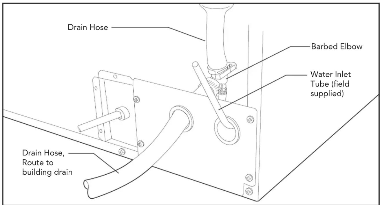
Back View, Gravity Drain Model

WARNING
ELECTRICAL SHOCK HAZARD
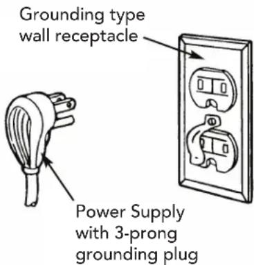
Failure to follow these instructions could result in fire or electrical shock.
The ice machine is supplied with a power cord. DO NOT remove the grounding pin from the cord's plug. DO NOT use extension cords. Follow all codes. Connect the machine to its own 115 volt, 15 amp circuit.
FINAL INSTALLATION
- If the electrical outlet for the ice maker is behind the unit, plug in the unit.
- Snap the black caps over the bottom of the leveling legs.
- Position the unit in the installation opening.
- Turn on the water supply. Make sure that the ice maker is plugged in and the power is on.
- Slide unit into installation opening, paying careful attention to water supply and drain connections. DO NOT kink!
-
Pour a couple of quarts of water into the ice storage bin; on drain pump equipped machines the drain pump should start and water should pump out. Check for leaks.
-
Replace the service access panel and insert access panel button cover (supplied)..
-
Level the unit as needed by turning the leveling legs clockwise to raise the unit and counterclockwise to lower the unit.
INSTALLATION CHECKLIST
- Has the unit been connected to the proper water supply?
- Has the water supply been checked for leaks?
- Has the unit been connected to a drain?
- Has the drain been tested for flow and leaks?
- Has the unit been connected to the proper electrical supply?
- Has the unit been leveled?
- Have all packing materials been removed from the machine?
- Has the door covering been installed?
SERVICE INFORMATION
If service is required, call your dealer or authorized service agency. The name of the authorized service agency can be obtained from the dealer or distributor in your area.
Have the following information readily available.
- Model number
- Serial number
- Date purchased
• Name of dealer from whom purchased
Clearly describe the problem that you are having. If you are unable to obtain the name of an authorized service agency, or if you continue to have service problems, contact Viking Range Corporation at 1-888- (845-4641), or write to:
VIKING RANGE, LLC
PREFERRED SERVICE
111 Front Street
Greenwood, Mississippi 38930 USA
Record the information indicated below. You will need it if service is ever required. The model and serial number for your ice machine are located upper left interior compartment.
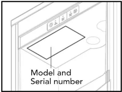
Model Number Serial Number
Date of Purchase
Date Installed
Dealer's Name
Address
If service requires installation of parts, use only authorized parts to insure protection under the warranty.
KEEP THIS MANUAL FOR FUTURE REFERENCE.
Viking Range, LLC
111 Front Street
Greenwood, Mississippi 38930 USA
(662) 455-1200
For product information,
call 1-888-(845-4641)
or visit our web site at vikingrange.com

Guide
d'Installation
natural_image
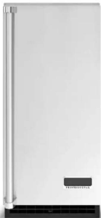
Exterior view of a modern stainless steel appliance with a black ventilation grille and 'PROFESSIONAL' label (no other text or symbols)5 SÉRIES
Machine à glaçons
Dimensions (Professional) 5
MISE AU REBUT CORRECTE (D'UN PRODUIT DE RÉFRIGÉRATION USAGÉ)

DANGER
RISQUE D'EMPRISONNEMENT D'ENFANT
natural_image
Line drawing of a single refrigerator with open lid and ventilation grilles (no text or symbols)DIMENSIONS (PROFESSIONAL)
Dimensions
FGIM/FPIM
natural_image
Exterior view of a modern office building (no signage)5 SERIE
natural_image
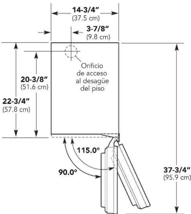
Line drawing of a single refrigerator with open lid and ventilation grilles (no text or symbols)DIMENSIONES (MODELO PROFESIONAL)
Giro de la puerta
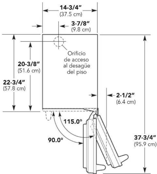
DIMENSIONES (PANELES PERSONALIZADOS)
Giro de la puerta
ESPECIFICACIONES
ESPECIFICACIONES
other
| Dimension | Value (cm) | |-----------|------------| | 13/9/16 | 34.4 | | 6-25/32 | 17.7 | | 8-1/4 | 20.9 | | 4-1/8 | 10.5 | | 13/32 | 1.3 | | 13/16" | 2.4 | | 14-11/16 | 37.3 | | Ø 1/8" | TÍPICO (10) | | 13-31/64 | 34.3 | | 13/32" | 1.3 | | 14-7/8" | 37.9 | | 30-5/16 | 77.0 |VIKING RANGE CORPORATION
PREFERRED SERVICE
111 Front Street
- TABLE OF CONTENTS
- IMPORTANT – PLEASE READ AND FOLLOW
- WARNING
- FOR YOUR SAFETY
- •SAVE THESE INSTRUCTIONS•
- PROPER DISPOSAL (OF OLD REFRIGERATION UNIT)
- DANGER
- RISK OF CHILD ENTRAPMENT
- IMPORTANT:
- DIMENSIONS (PROFESSIONAL)
- DIMENSIONS (CUSTOM PANEL)
- SPECIFICATIONS
- CUTOUT DIMENSIONS
- SPECIFICATIONS DRAIN/ELECTRICAL LOCATION
- GENERAL INFORMATION
- AIR FLOW
- Filters and Treatment
- RO Water
- INSTALLATION OVERVIEW
- INSTALLATION PARTS
- ACCESSORY DOOR PANEL
- CUSTOM PANEL
- DOOR PANEL ATTACHMENT
- DOOR SWING CHANGE
- To change:
- DOOR STOP
- HINGE COVERS
- KICKPLATE
- INSTALLATION NOTES
- WATER & DRAIN INSTALLATION
- DRAINS
- CAUTION
- ELECTRICAL SHOCK HAZARD
- FINAL INSTALLATION
- INSTALLATION CHECKLIST
- SERVICE INFORMATION
- Guide
- d'Installation
- MISE AU REBUT CORRECTE (D'UN PRODUIT DE RÉFRIGÉRATION USAGÉ)
- RISQUE D'EMPRISONNEMENT D'ENFANT
- DIMENSIONES (MODELO PROFESIONAL)
- DIMENSIONES (PANELES PERSONALIZADOS)
- ESPECIFICACIONES
- VIKING RANGE CORPORATION
- PREFERRED SERVICE
Brand : VIKING
Model : FGIM5151
Category : Ice Maker