
PowerLite Pro Z9800W - Video projector EPSON - Free user manual and instructions
Find the device manual for free PowerLite Pro Z9800W EPSON in PDF.
| Product type | Professional video projector |
| Brand | Epson |
| Model | PowerLite Pro Z9800W |
| Category | Video projector |
| Chassis dimensions (W x H x D) | 674 x 363 x 770 mm (without feet) |
| Chassis weight | Approximately 17.5 kg |
| Maximum load capacity (projector) | Approximately 32 kg |
| Maximum backup projector weight | 15 kg |
| Adjustment angle - horizontal tilt | ±2° (dial) / ±3° (feet) |
| Adjustment angle - horizontal rotation | ±5° |
| Adjustment angle - vertical tilt | ±2° (dial) / ±3° (feet) |
| Installation direction | Horizontal or vertical (portrait) |
| Projector stacking | Up to 2 projectors |
| Portrait projection | Yes (with dedicated chassis) |
| Stacked projection | Yes (with dedicated chassis) |
| Backup projector support | Yes, up to 15 kg |
| Safety | Safety instructions for installation (warnings) |
| Maintenance | Regular inspection of screws and damaged parts |
| Package contents | Upper chassis, lower chassis, installation plates, screws, stacking guides, stops |
| Required tools | Hex key (not included) |
| Chassis diameter | 30 mm |
Frequently Asked Questions - PowerLite Pro Z9800W EPSON
User questions about PowerLite Pro Z9800W EPSON
0 question about this device. Answer the ones you know or ask your own.
Ask a new question about this device
Download the instructions for your Video projector in PDF format for free! Find your manual PowerLite Pro Z9800W - EPSON and take your electronic device back in hand. On this page are published all the documents necessary for the use of your device. PowerLite Pro Z9800W by EPSON.
USER MANUAL PowerLite Pro Z9800W EPSON
natural_image
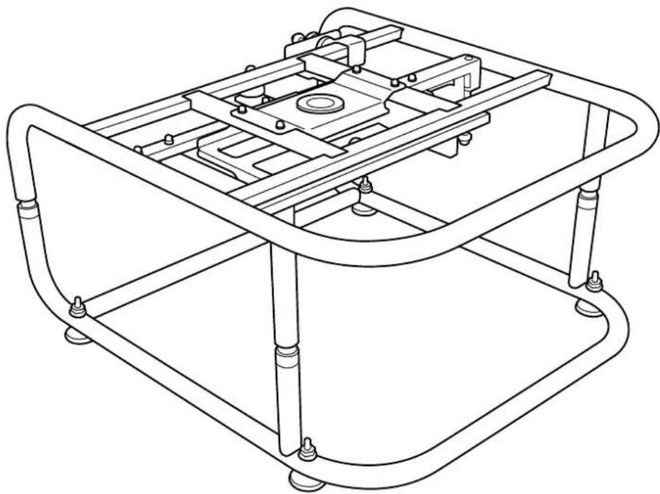
Technical line drawing of a mechanical assembly with curved frame and mounting feet (no text or symbols)使用说明书
使用説明書
取扱説明書
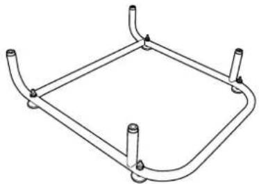
Frame ELPMB44
User's Guide

natural_image
Technical line drawing of a mechanical frame assembly (no text or symbols)
Safety Instructions
For your safety, read all the instructions in this guide before using this product. Incorrect handling that ignores instructions in this guide could damage this product or could result in personal injury or property damage. Keep this installation guide at hand for future reference.
Read the User's Guide and Safety Instructions for your projector and follow the instructions in these documents.
Safety indications
The documentation and this product use graphical symbols to show how to use this product safely.
The indications and their meaning are as follows. Make sure you understand them properly before reading the guide.
| Indication Explanation | |
 Warning Warning | This symbol indicates information that, if ignored, could result in personal injury or even death due to incorrect handling. |
 Caution Caution | This symbol indicates information that, if ignored, could result in personal injury or physical damage due to incorrect handling. |
Explanation of Symbols
| Symbols Explanation | |
 | Indicates actions that must not be performed. |
 | Indicates actions that should be performed. |
| Attention | Indicates contents that could cause damage or malfunction to this product or the projector. |
 | Indicates related or useful information. |
Safety Precautions for Installation
 Warning Warning | |
| Follow the instructions in this guide when installing this product.If the instructions are not followed, this product may fall, resulting in personal injury or an accident. |  |
| Do not install this product in an unstable location.Make sure the installation location is strong enough to support the weight of the projector and this product. |  |
| Do not use adhesives, lubricant, oil, and so on when securing the screws.If you use adhesives on the mount fixing points to prevent the screws from loosening, or if you use things such as lubricants or oils on the projector, the projector case may crack and cause the projector to fall, resulting in personal injury or property damage. |  |
| This product is for portrait projection or stacked projection only. Do not attach any devices other than the projector.Otherwise this product may be damaged; if the projector falls, it could cause death or personal injury. |  |
| This product should be installed by at least two qualified service personnel.When loosening screws during installation, be careful not to drop this product.If this product or the projector falls, it could cause death or personal injury. |  |
| After making adjustments, make sure you tighten all of the screws.Otherwise, the product may fall and cause personal injury or property damage. |  |
| Wear non-slip gloves when moving and installing.If this product falls, it could cause personal injury or property damage. |  |
| Do not cover the projector's air intake vent or air exhaust vent.If either of the vents is covered, the internal temperature could rise and cause a fire. |  |

| Do not install this product in a location subject to temperatures outside the projector's operating range.This may cause malfunctions to occur. |  |
| Do not install the projector in a location where it may be subject to vibrations or shocks. |  |
| When securing the frame with bolts, make sure you do not catch your hand or finger between the bolts and the frame. |  |
| Do not stack more than three projectors in a stacked configuration.The frame could fall and cause an injury. |  |
Notes on Usage
 Warning Warning | |
| Modifying and disassembling should only be performed by qualified service personnel except when explicitly stated in the User's Guide.Otherwise, malfunctions or accidents may occur. |  |
| Do not hang from this product.Also, do not hang any objects on this product except for the projector.If this product breaks and falls, it could cause death or personal injury. |  |
| Do not stand or sit on this product.Otherwise, the product could be damaged. |  |
| Periodically check that there are no damaged sections or loose screws.If any parts are damaged, stop using the product immediately.If this product or the projector falls, it could cause death or personal injury. |  |
 Caution Caution | |
| Do not apply too much force when adjusting this product.Otherwise, the product may break and cause an injury. |  |
| Do not place screws or feet within reach of small children.Children may swallow them by accident.If this happens, contact a doctor immediately. |  |

Product Features
| Portrait Projection | |
| For projectors that support portrait projection, you can perform portrait projection by placing a projector in the frame, and then installing the frame vertically. | |
 | |
| Stacked Projection | |
| You can secure a projector to this product, and stack up to two projectors. | |
 | |
 · You can also install projector installation plates on the frame, and place the projector. · You can stack two frames and place a backup projector on top. · This product can support a backup projector that weighs up to 15 kg. · You can also install projector installation plates on the frame, and place the projector. · You can stack two frames and place a backup projector on top. · This product can support a backup projector that weighs up to 15 kg. |

Package Contents
The following parts are supplied with this product. Make sure that all of the parts are supplied.
If there is anything missing or if there are damaged parts, contact the store where you purchased the product.
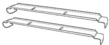
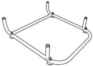
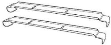
Top Frame (x1) Bottom Frame (x1) Projector Installation Plates (x2)
natural_image
Technical line drawing of a mechanical frame assembly (no text or symbols)Screws for securing the Projector Installation Plates (x2)
natural_image
Line drawing of a square metal frame with four corner posts (no text or symbols)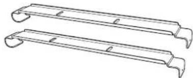
natural_image
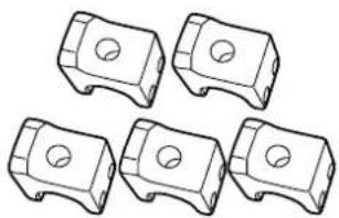
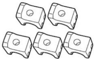
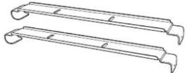
Two identical metal frame structures with curved ends and notches, shown in line drawing style (no text or symbols)Stacking Guides (x5) Stoppers (x4)


natural_image
Five identical mechanical component diagrams with circular holes, shown in isometric view (no text or symbols)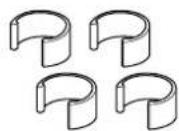
| Shape Name | Number | Usage | |
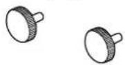
| M6 x 30 mm hexagon socket head cap bolt with washer/spring washer | 4 For attaching the projector | ||
| M6 x 40 mm hexagon socket head cap bolt M6 hexagon nut | 10 For attaching the Stacking Guides | ||
Use the bolts or screws supplied with this product to install it as directed in this guide. Do not substitute these bolts with any other types.

• Gather the tools and parts you need before you begin installation.
- Dispose of this product in accordance with your local laws and regulations. Follow the disposal regulations of your workplace if they apply.

Attaching to the Projector
Attention
- Do not remove screws for parts that are not specified in this guide.
- Make sure the screws to secure the projector to this product, as well as the metal fittings to connect the top and bottom frames are secured.
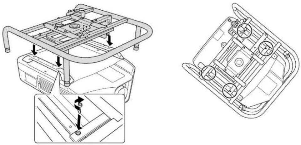
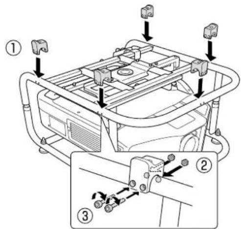
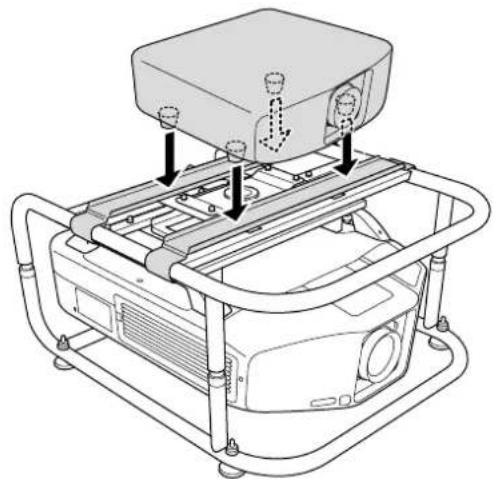
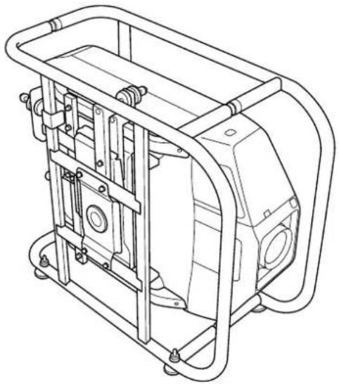
1 Attach the top frame to the projector.
Align the bolt holes on the top frame with the ceiling mount fixing points (four points).
Use a commercially available hexagon wrench to tighten the M6 x 30 mm bolts (with washers/spring washers) supplied, and then secure the frame.
natural_image
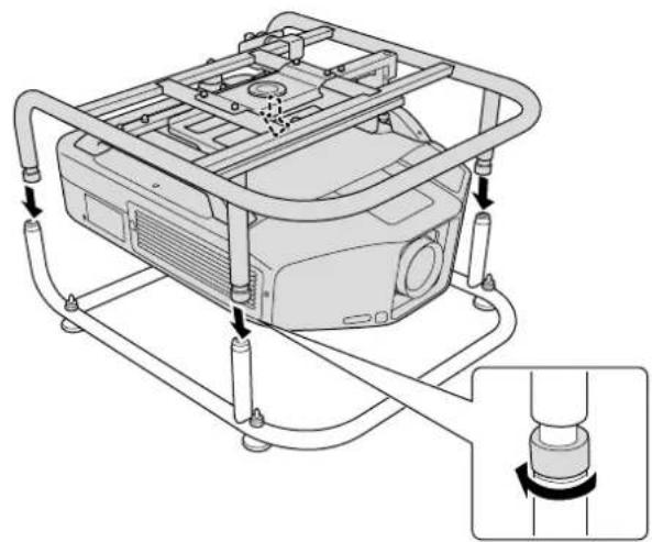
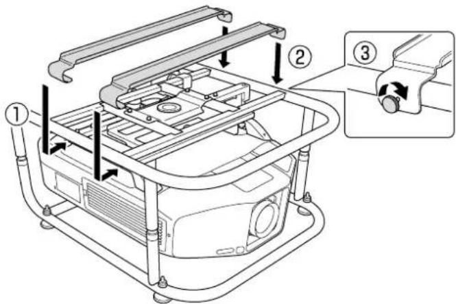
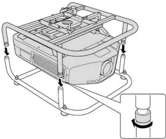
Technical line drawing of a vehicle chassis with structural components and mounting details (no text or symbols)Attach the top frame to the bottom frame.
Align the Top Frame with the Bottom Frame, and rotate the metal fittings (four points) to secure them in place.
natural_image
Technical line drawing of a mechanical device with tubing and a close-up inset showing a cylindrical component (no text or symbols)

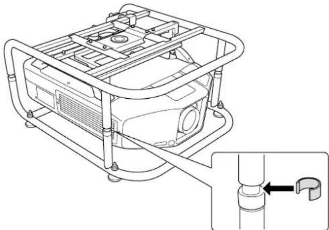
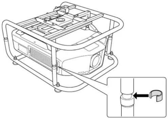
Attach the stoppers (four points).
natural_image
Technical line drawing of a mechanical device with a pipe fitting and a close-up inset showing a pipe connection (no text or symbols)
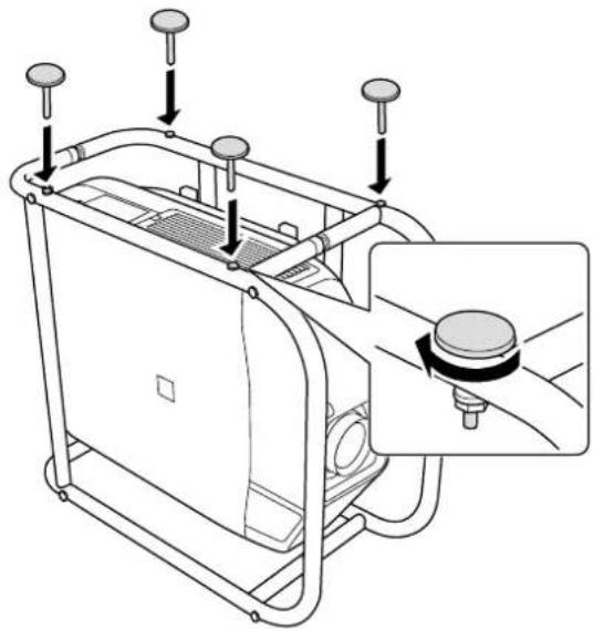
Remove the projector's feet.
See the User's Guide supplied with the projector for information on how to remove the feet.
Attention
- If the projector's feet are left attached, they could interfere with the frame during angle adjustment.
- Do not place the projector directly on the floor and so on while the projector's feet are removed.

Adjusting the Installation Angle
You can adjust the projector's angle using the three adjustment dials and the feet.
Tilt the projector, or rotate horizontally to adjust the position of the projected image.
| Adjustable Range for the Adjustment Dial | Adjustable Range for the Feet | |
| Tilt adjustment | 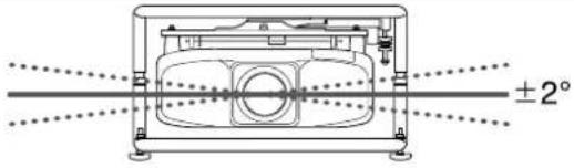 | 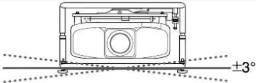 |
| Horizontal adjustment | 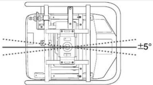 | |
| Vertical adjustment | 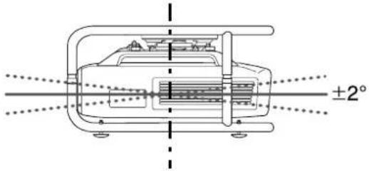 |  |

Make sure that the installation angle is within the specified range. See the User's Guide supplied with the projector for information on the angle of tilt.
Adjusting the Angle Using the Adjustment Dial
You can adjust the tilt (±2°) and direction (horizontally ±5°, vertically ±2°) of the set projector.
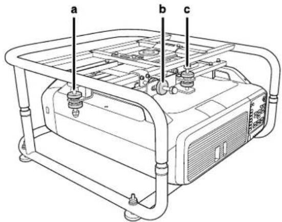
a: For adjusting the tilt
b: For adjusting the horizontal angle
c: For adjusting the vertical angle

Caution
When rotating the adjustment dials, make sure you do not catch your hand or finger between the dials.
a: For adjusting the tilt
| Adjust to the + side | Rotate adjustment dial A in the + direction first, and then rotate adjustment dial B in the + direction to secure them in place. |
| Adjust to the - side | Rotate adjustment dial B in the - direction first, and then rotate adjustment dial A in the - direction to secure them in place. |
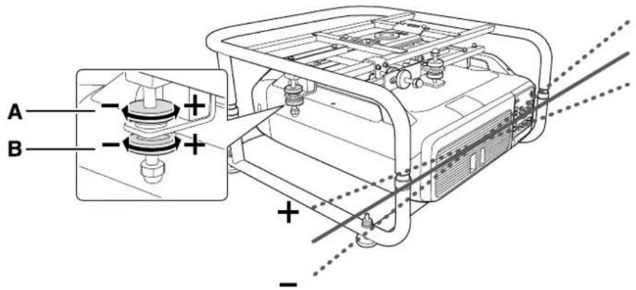
After making adjustments, make sure that adjustment dials A and B are not loose.
b: For adjusting the horizontal angle
| Adjust to the + side | Rotate adjustment dial A in the + direction first, and then rotate adjustment dial B in the + direction to secure them in place. |
| Adjust to the - side | Rotate adjustment dial B in the - direction first, and then rotate adjustment dial A in the - direction to secure them in place. |

After making adjustments, make sure that adjustment dials A and B are not loose.
c: For adjusting the vertical angle
| Adjust to the + side | Rotate adjustment dial B in the + direction first, and then rotate adjustment dial A in the + direction to secure them in place. |
| Adjust to the - side | Rotate adjustment dial A in the - direction first, and then rotate adjustment dial B in the - direction to secure them in place. |
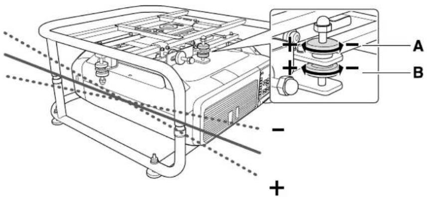
After making adjustments, make sure that adjustment dials A and B are not loose.
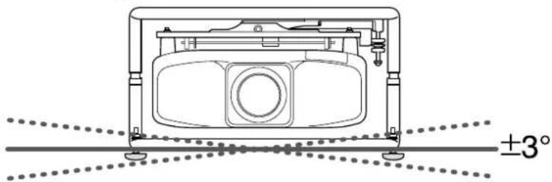
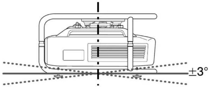
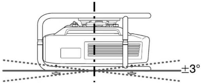
Adjusting the Angle Using the Feet
When the frame is placed on the floor, you can adjust the installation angle with the feet. You can adjust the tilt (horizontal ±3^ ) and direction (vertically ±3^ ) of the projector.
Adjusting the tilt: Use the left and right feet.
natural_image
Technical line drawing of a mechanical device with mounting feet and a central circular component, showing angular measurement ±3° (no text or symbols beyond basic geometry)Adjusting the horizontal angle: Use the front and back feet.

Attention
The feet can be attached and removed. Note that the feet will detach if they are extended too far.

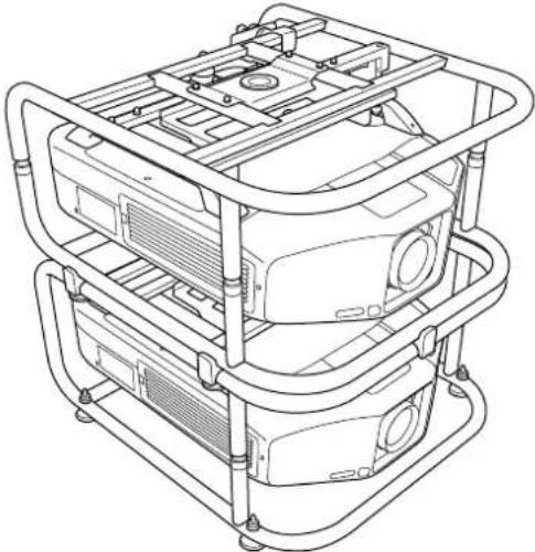
Portrait Projection
You can perform portrait projection by placing the projector in the frame, and then installing the frame vertically.

See the User's Guide supplied with the projector to check if your projector supports portrait projection.
1
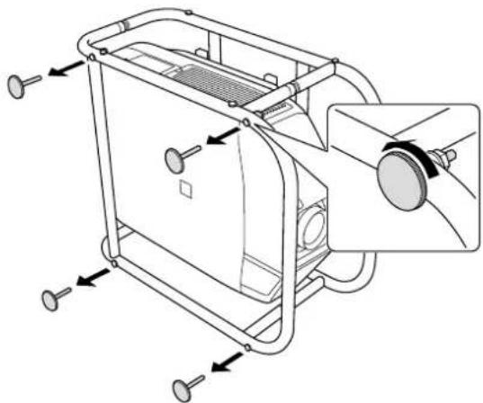
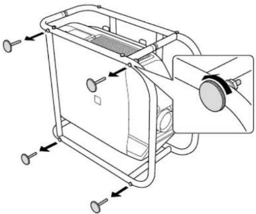
Remove the feet (four points) from the bottom frame.
natural_image
Technical line drawing of a mechanical device with mounting holes and a central component (no text or symbols)2
Attach the removed feet (four points) to the side of the frame.
There are screw holes on the side to which you can attach the feet. Make sure you do not attach them to the wrong side.
natural_image
Technical line drawing of a mechanical device with mounting holes and a close-up inset showing internal components (no text or symbols)
With the feet facing down, stand the frame vertically.

natural_image
Technical line drawing of a mechanical device housing with mounting brackets and internal components (no text or symbols)
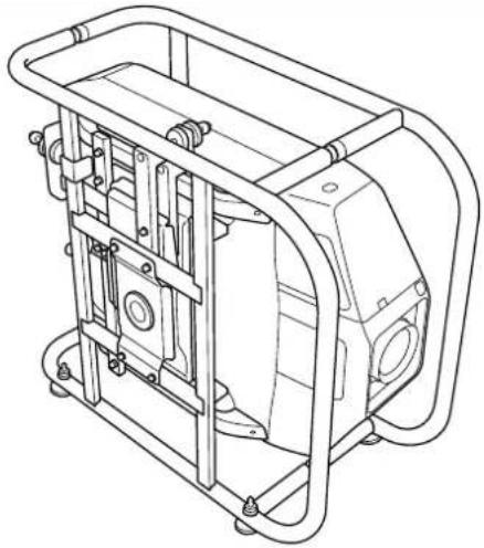
Stacking Two Projectors
You can stack up to two frames.

Warning
When stacking two frames, do not suspend them from a ceiling and so on.
If this product or the projector falls, it could cause death or personal injury.

Caution
Do not stack more than three frames for stacked projection.
The frame could fall and cause an injury.

Attach the stacking guides (five points) to the frame that will be at the bottom of the stack.
Use a commercially available hexagon wrench to tighten the M6 x 40 mm bolts (with hexagon nuts) supplied to secure the guides.
Use two bolts to secure each stacking guide.

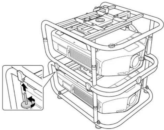
Remove the four feet from the bottom frame that will be at the top of the stack.
natural_image
Technical line drawing of a mechanical device with mounting holes and internal components (no text or symbols)
Place the frame that will be at the top of the stack on the stacking guides, and secure it with the feet removed in step 2.
Use the feet to secure the four points on the left and right of the frame.
natural_image
Technical line drawing of a multi-level industrial machine with structural brackets and mounting holes (no text or symbols)
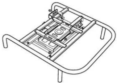
Installing the Backup Projector
By installing the projector installation plate, you can place a backup projector on the frame.

• This product can support a backup projector that weighs up to 15 kg.
- You can stack two frames and place a backup projector on top.

Align the holes on the projector installation plate with the screw holes of the top frame. Secure the projector installation plate with the screws supplied (two points).

Adjust the position of the projector installation plate, and then place the backup projector.
Align the position of the projector installation plate with the position of the backup projector's feet, and then place the backup projector.
natural_image
Technical line drawing of a mechanical assembly with mounting brackets and a central component (no text or symbols)Attention
Do not secure the projector installation plate with a fastening belt and so on. Otherwise the projector installation plate could be deformed.

Specifications
Projector Specifications
| Installation Direction Horizontally/Vertically | * Projectors can only be stacked horizontally. | |
| Adjustment Angle | Horizontal Tilt Adjustment dial: ±2°, feet ±3°* You can adjust up to ±5°. | |
| Horizontal Rotation Adjustment dial: ±5° | ||
| Vertical Tilt Adjustment dial: ±2°, feet ±3°* You can adjust up to ±5°. | ||
| Maximum load capacity Approx. 32 kg | ||
| Maximum Weight for Backup Projector 15 kg | ||
| Frame Diameter 30 mm | ||
| External Dimensions 674 (W) x 363 (H) x 770 (D) mm (not including raised section) | ||
| Frame weight Approx. 17.5 kg | ||
External Dimensions
Values are just reference.
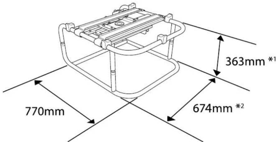
*1: Value when the feet are removed. 381 mm when the feet are attached.
*2: Value when the feet are removed. 695 mm when the feet are attached.

Trademarks and Copyrights
Other product names used herein are for identification purposes only and may be trademarks of their respective owners. Epson disclaims any and all rights in those marks.
© SEIKO EPSON CORPORATION 2014. All rights reserved.
Rahmen ELPMB44
Bedienungsanleitung

natural_image
Technical line drawing of a mechanical frame assembly (no text or symbols)
natural_image
Technical line drawing of a mechanical frame assembly (no text or symbols)natural_image
Pure technical line drawing of a mechanical frame or bracket (no text or symbols)natural_image
Two identical metal trapezoidal plates with curved ends and notches, shown side by side (no text or symbols)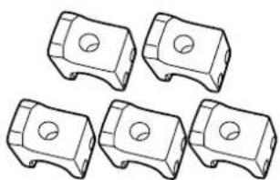
natural_image
Five identical mechanical component diagrams with circular holes, shown in side view (no text or symbols)
natural_image
Technical diagram of a car interior with structural components and mounting points (no text or symbols)
natural_image
Technical line drawing of a vehicle chassis frame with mounting brackets and structural components (no text or symbols)2
natural_image
Technical line drawing of a mechanical device with tubing and a close-up inset showing a cylindrical component (no text or symbols)
natural_image
Technical line drawing of a mechanical device with a close-up inset showing a pipe fitting (no text or symbols)
natural_image
Technical line drawing of a mechanical device with mounting feet and a central circular component, showing angular measurement ±3° (no text or symbols beyond basic geometry)natural_image
Technical line drawing of a mechanical device with mounting holes and internal components (no text or symbols)2
natural_image
Technical line drawing of a mechanical device with adjustment knobs and a circular component (no text or symbols)
natural_image
Technical line drawing of a mechanical device with frame and mounting brackets (no text or symbols)

natural_image
Technical line drawing of a mechanical device with mounting holes and internal components (no text or symbols)
natural_image
Technical line drawing of a multi-level electronic device with mounting brackets and internal components, showing a close-up inset of the component (no text or symbols present)

natural_image
Technical line drawing of a vehicle chassis with mounting brackets and control panel (no text or symbols)Achtung
© SEIKO EPSON CORPORATION 2014. All rights reserved.
Châssis ELPMB44
natural_image
Technical line drawing of a mechanical frame assembly (no text or symbols)
natural_image
Technical line drawing of a mechanical assembly with no visible text or symbolsnatural_image
Pure line drawing of a rectangular frame with four vertical posts and curved ends (no text or symbols)natural_image
Two identical metal frame structures with curved ends and notches, shown in line drawing style (no text or symbols)
natural_image
Five identical mechanical component diagrams with circular holes, shown in isometric view (no text or symbols)
natural_image
Technical diagram of a vehicle chassis with structural components and mounting bracket (no text or symbols)
natural_image
Technical line drawing of a vehicle chassis frame with four circular components (no text or symbols)natural_image
Technical line drawing of a mechanical device with tubing and a close-up inset showing a rotating component (no text or symbols)1

natural_image
Technical line drawing of a mechanical device with a close-up inset showing a pipe fitting (no text or symbols)
natural_image
Technical line drawing of a mechanical component with alignment lines and a 3° angle标注 (no text or symbols beyond basic geometry)natural_image
Technical line drawing of a mechanical device with mounting holes and internal components (no text or symbols)2
natural_image
Technical line drawing of a mechanical device with adjustment knobs and a close-up inset showing a circular component (no text or symbols)
natural_image
Technical line drawing of a mechanical device housing with mounting brackets and internal components (no text or symbols)
2
natural_image
Technical line drawing of a mechanical device with mounting holes and a close-up view of the internal components (no text or symbols)
natural_image
Technical line drawing of a multi-tiered industrial machine with visible internal components and mounting brackets (no text or symbols)

natural_image
Technical line drawing of a mechanical device with mounting brackets and internal components (no text or symbols)Attention
© SEIKO EPSON CORPORATION 2014. All rights reserved.
Telaio ELPMB44
Manuale dell'utente
natural_image
Technical line drawing of a mechanical frame assembly (no text or symbols)
natural_image
Technical line drawing of a mechanical assembly with no visible text or symbolsnatural_image
Pure line drawing of a rectangular frame with four corner supports (no text or symbols)natural_image
Five identical mechanical component diagrams with circular holes, shown in isometric view (no text or symbols)proiettore (x2)
natural_image
Two identical metal bracket-like structures with curved ends and notches, shown in line drawing style (no text or symbols)
natural_image
Technical line drawing of a vehicle chassis with structural components and mounting brackets (no text or symbols)natural_image
Technical line drawing of a mechanical device with tubing and a close-up inset showing a cylindrical component (no text or symbols)
natural_image
Technical line drawing of a mechanical device with a close-up inset showing a pipe fitting (no text or symbols)
natural_image
Technical line drawing of a mechanical component with mounting holes and a central circular feature, shown with alignment lines (no text or symbols)natural_image
Technical line drawing of a mechanical device with mounting holes and internal components (no text or symbols)
natural_image
Technical line drawing of a mechanical device with mounting holes and a close-up inset showing a circular component (no text or symbols)
natural_image
Technical line drawing of a mechanical device with frame and housing (no text or symbols)
2
natural_image
Technical line drawing of a mechanical device with mounting holes and internal components (no text or symbols)
natural_image
Technical line drawing of a multi-tiered industrial machine with mounting brackets and internal components, showing a close-up inset of the component (no text or symbols present)

natural_image
Technical line drawing of a mechanical assembly with mounting brackets and a central component (no text or symbols)Attenzione
© SEIKO EPSON CORPORATION 2014. All rights reserved.
Armazón ELPMB44
Manual de usuario

natural_image
Technical line drawing of a mechanical frame assembly (no text or symbols)
natural_image
Technical line drawing of a mechanical assembly with no visible text or symbolsnatural_image
Line drawing of a four-legged metal frame with curved legs and mounting feet (no text or symbols)natural_image
Two identical metal trapezoidal plates with curved ends and evenly spaced slots (no text or symbols)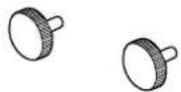
natural_image
Five identical mechanical component diagrams with circular holes, shown in isometric view (no text or symbols)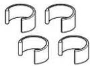
natural_image
Technical line drawings of a vehicle chassis with structural components and mounting points (no text or symbols)2
natural_image
Technical line drawing of a mechanical device with attached tubing and a close-up inset showing a cylindrical component (no text or symbols)
natural_image
Technical line drawing of a mechanical device with a close-up inset showing a pipe fitting (no text or symbols)
natural_image
Technical line drawing of a mechanical device with mounting feet and a central circular component, showing angular measurement ±3° (no text or symbols beyond basic geometry)natural_image
Technical line drawing of a mechanical device with mounting holes and internal components (no text or symbols)2
natural_image
Technical line drawing of a mechanical device with mounting holes and a close-up inset showing internal components (no text or symbols)
natural_image
Technical line drawing of a mechanical device housing with mounting brackets and internal components (no text or symbols)
2
natural_image
Technical line drawing of a mechanical device with mounting holes and internal components (no text or symbols)
natural_image
Technical line drawing of a multi-tiered electronic device with mounting brackets and internal components, showing a close-up inset of the component (no text or symbols present)
natural_image
Technical line drawing of a mechanical assembly with mounting brackets and a central component (no text or symbols)Atención
© SEIKO EPSON CORPORATION 2014. All rights reserved.
Estrutura ELPMB44
Manual do Utilizador

natural_image
Technical line drawing of a mechanical frame assembly (no text or symbols)
natural_image
Technical line drawing of a mechanical frame assembly (no text or symbols)natural_image
Pure line drawing of a rectangular frame with four corner supports (no text or symbols)Guias de empilhamento (x5) Fixadores (x4)
natural_image
Two identical metal frame structures with curved ends and notches, shown in line drawing style (no text or symbols)
natural_image
Five identical mechanical component diagrams with circular holes, shown in isometric view (no text or symbols)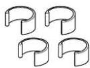
natural_image
Technical diagram of a vehicle chassis with structural components and mounting points, showing assembly details (no text or symbols)
natural_image
Technical line drawing of a vehicle chassis frame with mounting holes and structural components (no text or symbols)2
Fixe a estrutura superior à estrutura inferior.
natural_image
Technical line drawing of a mechanical device with tubing and a close-up inset showing a cylindrical component (no text or symbols)
natural_image
Technical line drawing of a mechanical device with a close-up inset showing a pipe fitting (no text or symbols)
natural_image
Technical line drawing of a mechanical device with mounting feet and a central circular component, showing angular measurement ±3° (no text or symbols beyond basic geometry)natural_image
Technical line drawing of a mechanical device with mounting holes and a circular component (no text or symbols)2
natural_image
Technical line drawing of a mechanical device with mounting holes and a close-up inset showing a circular component (no text or symbols)
natural_image
Technical line drawing of a mechanical device housing with mounting brackets and internal components (no text or symbols)
2
natural_image
Technical line drawing of a mechanical device with mounting holes and internal components (no text or symbols)
natural_image
Technical line drawing of a multi-tiered electronic device with mounting brackets and internal components, showing a close-up inset of the component (no text or symbols present)
Instalar o projector de reserva

natural_image
Technical line drawing of a mechanical assembly with mounting brackets and a central component (no text or symbols)Attention
© SEIKO EPSON CORPORATION 2014. All rights reserved.
框架 ELPMB44
使用说明书

natural_image
Technical line drawing of a mechanical frame assembly (no text or symbols)
安全使用须知
natural_image
Technical line drawing of a mechanical assembly with no visible text or symbols用于固定投影机安装板的螺丝
(x2)


下部框架 (x1)

natural_image
Line drawing of a square metal frame with four corner posts (no text or symbols)堆放导轨 (x5) 封堵器 (x4)
投影机安装板 (x2)
natural_image
Two identical metal trapezoidal plates with curved ends, no text or symbols present.
natural_image
Five identical mechanical component diagrams arranged in a row (no text or symbols)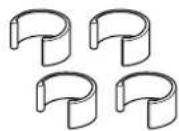
natural_image
Technical diagram of a vehicle chassis with structural components and mounting points (no text or symbols)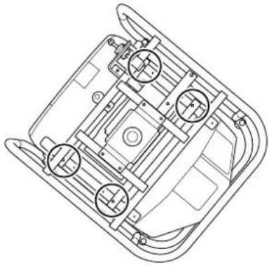
natural_image
Technical line drawing of a vehicle chassis frame with four circular components (no text or symbols)2 将上部框架安装到下部框架。
natural_image
Technical line drawing of a mechanical device with tubing and a close-up inset showing a cylindrical component (no text or symbols)将上部框架对齐下部框架,旋转金属装置(四个点)以将它们固定到位。
2 将上部框架安装到下部框架。
将上部框架对齐下部框架,旋转金属装置(四个点)以将它们固定到位。

3 安装封堵器(四个点)。
natural_image
Technical line drawing of a mechanical device with a close-up inset showing a pipe fitting (no text or symbols)卸下投影机的撑脚。
natural_image
Technical line drawing of a mechanical component with mounting holes and alignment lines (no text or symbols)调整水平角度:使用前后撑脚。
注意
natural_image
Technical line drawing of a mechanical device with mounting holes and a close-up inset showing a circular component (no text or symbols)2
将卸下的撑脚(四个点)安装在框架侧面。
natural_image
Technical line drawing of a mechanical device with adjustment knobs and a close-up inset showing internal components (no text or symbols)

撑脚朝下时,使框架保持垂直。
natural_image
Technical line drawing of a mechanical device with frame and mounting brackets (no text or symbols)
堆放两台投影机
您可以堆放最多两个框架。
natural_image
Technical line drawing of a mechanical device with mounting holes and internal components (no text or symbols)
natural_image
Technical line drawing of a multi-tiered electronic device with mounting brackets and internal components, showing a close-up inset of the component (no text or symbols present)
安装备用投影机
natural_image
Technical line drawing of a mechanical assembly with mounting brackets and control elements (no text or symbols)注意
© SEIKO EPSON CORPORATION 2014. All rights reserved.
框架 ELPMB44
使用説明書

natural_image
Technical line drawing of a mechanical frame assembly (no text or symbols)
安全使用須知
natural_image
Technical line drawing of a mechanical assembly with no visible text or symbols用於固定投影機安裝板的螺絲 (x2)
下框架 (x1)
natural_image
Line drawing of a rectangular frame with four vertical posts and curved legs (no text or symbols)堆疊導件 (x5) 阻擋器 (x4)
投影機安裝板 (x2)

natural_image
Two identical metal trapezoidal plates with curved ends, shown in line drawing style (no text or symbols)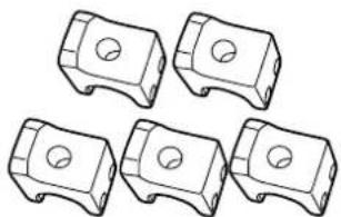
natural_image
Five identical mechanical component diagrams with circular holes, shown in side profile (no text or symbols)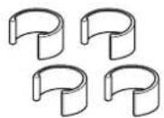
natural_image
Technical diagram of a vehicle chassis with structural components and mounting points (no text or symbols)
natural_image
Technical line drawing of a vehicle chassis with four circular components (no text or symbols)2
將上框架安裝至下框架。
natural_image
Technical line drawing of a mechanical device with tubing and mounting base, showing internal components and a close-up inset of a cylindrical component (no text or symbols)3
安裝阻擋器 (四點)。

natural_image
Technical line drawing of a mechanical device with a close-up inset showing a pipe fitting (no text or symbols)4
取下投影機的撐腳。
natural_image
Technical line drawing of a mechanical device with mounting feet and a central circular component, showing angular measurement ±3° (no text or symbols beyond basic geometry)調整水平角度:使用前撐腳和後撐腳。
natural_image
Technical line drawing of a mechanical device with angular dimension标注 (±3°), no readable text or symbols present.注意
natural_image
Technical line drawing of a mechanical device with mounting holes and a close-up view of the internal components (no text or symbols)
natural_image
Technical line drawing of a mechanical device with mounting holes and a close-up inset showing a circular component (no text or symbols)3
撐腳朝下後,請將框架直立。

natural_image
Technical line drawing of a mechanical device with frame and mounting brackets (no text or symbols)
堆疊兩部投影機
您最多可以堆疊兩部投影機。

從將位於堆疊上層的下框架取下四個撐腳。

natural_image
Technical line drawing of a mechanical device with mounting holes and internal components (no text or symbols)
natural_image
Technical line drawing of a multi-level industrial machine with structural brackets and mounting holes (no text or symbols)
安裝備用投影機

natural_image
Technical line drawing of a mechanical assembly with mounting brackets and control panel (no text or symbols)注意
© SEIKO EPSON CORPORATION 2014. All rights reserved.
フレーム ELPMB44
取扱説明書

natural_image
Technical line drawing of a mechanical frame assembly (no text or symbols)
安全上のご注意
natural_image
Technical line drawing of a mechanical assembly with no visible text or symbolsnatural_image
Line drawing of a square frame with four vertical posts and curved legs (no text or symbols)スタック用ガイド(5個)
natural_image
Two identical metal frame structures with curved ends and mounting holes (no text or symbols)ゆるみ止め用ストッパー(4個)

natural_image
Five identical mechanical component diagrams with circular holes, shown in isometric view (no text or symbols)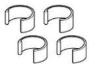
natural_image
Technical diagram of a mechanical assembly with mounting brackets and a close-up view of a component (no text or symbols)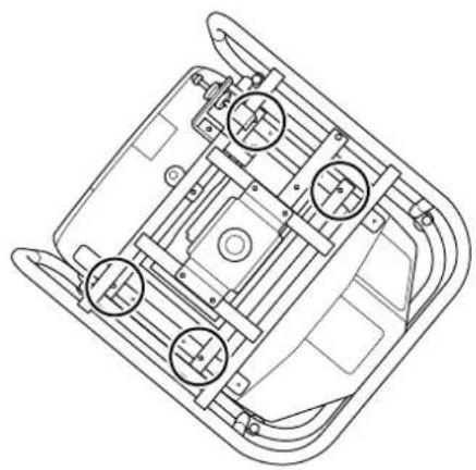
natural_image
Technical line drawing of a vehicle chassis with mounting brackets and structural elements (no text or symbols)natural_image
Technical line drawing of a mechanical device with tubing and a close-up inset showing a cylindrical component (no text or symbols)
3
natural_image
Technical line drawing of a mechanical device with a close-up inset showing a pipe fitting (no text or symbols)4
プロジェクターのフットを取り外します。
natural_image
Technical line drawing of a mechanical device with mounting brackets and alignment lines (no text or symbols)natural_image
Technical line drawing of a mechanical device with angular dimension标注 (±3°), no readable text or symbols present.注意
natural_image
Technical line drawing of a mechanical device with mounting holes and internal components (no text or symbols)natural_image
Technical line drawing of a mechanical device with mounting holes and a close-up inset showing internal components (no text or symbols)
natural_image
Technical line drawing of a mechanical device with mounting brackets and internal components (no text or symbols)
2段に重ねて使用する
natural_image
Technical line drawing of a mechanical device with mounting holes and a central hub (no text or symbols)

natural_image
Technical line drawing of a multi-level industrial machine with structural brackets and mounting holes (no text or symbols)

natural_image
Technical line drawing of a mechanical device with mounting brackets and internal components (no text or symbols)注意
© SEIKO EPSON CORPORATION 2014. All rights reserved.
EPSON
EXCEED YOUR VISION